EP0286233A2 - Wasserelektrolyse-Vorrichtung - Google Patents
Wasserelektrolyse-Vorrichtung Download PDFInfo
- Publication number
- EP0286233A2 EP0286233A2 EP88301961A EP88301961A EP0286233A2 EP 0286233 A2 EP0286233 A2 EP 0286233A2 EP 88301961 A EP88301961 A EP 88301961A EP 88301961 A EP88301961 A EP 88301961A EP 0286233 A2 EP0286233 A2 EP 0286233A2
- Authority
- EP
- European Patent Office
- Prior art keywords
- electrolysis
- water
- ionized
- water discharge
- channel
- Prior art date
- Legal status (The legal status is an assumption and is not a legal conclusion. Google has not performed a legal analysis and makes no representation as to the accuracy of the status listed.)
- Granted
Links
Images


Classifications
-
- C—CHEMISTRY; METALLURGY
- C02—TREATMENT OF WATER, WASTE WATER, SEWAGE, OR SLUDGE
- C02F—TREATMENT OF WATER, WASTE WATER, SEWAGE, OR SLUDGE
- C02F1/00—Treatment of water, waste water, or sewage
- C02F1/46—Treatment of water, waste water, or sewage by electrochemical methods
- C02F1/461—Treatment of water, waste water, or sewage by electrochemical methods by electrolysis
- C02F1/46104—Devices therefor; Their operating or servicing
- C02F1/4618—Devices therefor; Their operating or servicing for producing "ionised" acidic or basic water
-
- C—CHEMISTRY; METALLURGY
- C02—TREATMENT OF WATER, WASTE WATER, SEWAGE, OR SLUDGE
- C02F—TREATMENT OF WATER, WASTE WATER, SEWAGE, OR SLUDGE
- C02F1/00—Treatment of water, waste water, or sewage
- C02F1/46—Treatment of water, waste water, or sewage by electrochemical methods
- C02F1/461—Treatment of water, waste water, or sewage by electrochemical methods by electrolysis
- C02F1/46104—Devices therefor; Their operating or servicing
- C02F1/46109—Electrodes
- C02F2001/46133—Electrodes characterised by the material
-
- C—CHEMISTRY; METALLURGY
- C02—TREATMENT OF WATER, WASTE WATER, SEWAGE, OR SLUDGE
- C02F—TREATMENT OF WATER, WASTE WATER, SEWAGE, OR SLUDGE
- C02F1/00—Treatment of water, waste water, or sewage
- C02F1/46—Treatment of water, waste water, or sewage by electrochemical methods
- C02F1/461—Treatment of water, waste water, or sewage by electrochemical methods by electrolysis
- C02F1/46104—Devices therefor; Their operating or servicing
- C02F1/46109—Electrodes
- C02F2001/46152—Electrodes characterised by the shape or form
-
- C—CHEMISTRY; METALLURGY
- C02—TREATMENT OF WATER, WASTE WATER, SEWAGE, OR SLUDGE
- C02F—TREATMENT OF WATER, WASTE WATER, SEWAGE, OR SLUDGE
- C02F2201/00—Apparatus for treatment of water, waste water or sewage
- C02F2201/002—Construction details of the apparatus
- C02F2201/003—Coaxial constructions, e.g. a cartridge located coaxially within another
-
- C—CHEMISTRY; METALLURGY
- C02—TREATMENT OF WATER, WASTE WATER, SEWAGE, OR SLUDGE
- C02F—TREATMENT OF WATER, WASTE WATER, SEWAGE, OR SLUDGE
- C02F2201/00—Apparatus for treatment of water, waste water or sewage
- C02F2201/46—Apparatus for electrochemical processes
- C02F2201/461—Electrolysis apparatus
- C02F2201/46105—Details relating to the electrolytic devices
- C02F2201/46115—Electrolytic cell with membranes or diaphragms
-
- C—CHEMISTRY; METALLURGY
- C02—TREATMENT OF WATER, WASTE WATER, SEWAGE, OR SLUDGE
- C02F—TREATMENT OF WATER, WASTE WATER, SEWAGE, OR SLUDGE
- C02F2201/00—Apparatus for treatment of water, waste water or sewage
- C02F2201/46—Apparatus for electrochemical processes
- C02F2201/461—Electrolysis apparatus
- C02F2201/46105—Details relating to the electrolytic devices
- C02F2201/4612—Controlling or monitoring
- C02F2201/46125—Electrical variables
- C02F2201/4613—Inversing polarity
-
- C—CHEMISTRY; METALLURGY
- C02—TREATMENT OF WATER, WASTE WATER, SEWAGE, OR SLUDGE
- C02F—TREATMENT OF WATER, WASTE WATER, SEWAGE, OR SLUDGE
- C02F2201/00—Apparatus for treatment of water, waste water or sewage
- C02F2201/46—Apparatus for electrochemical processes
- C02F2201/461—Electrolysis apparatus
- C02F2201/46105—Details relating to the electrolytic devices
- C02F2201/4612—Controlling or monitoring
- C02F2201/46145—Fluid flow
-
- C—CHEMISTRY; METALLURGY
- C02—TREATMENT OF WATER, WASTE WATER, SEWAGE, OR SLUDGE
- C02F—TREATMENT OF WATER, WASTE WATER, SEWAGE, OR SLUDGE
- C02F2201/00—Apparatus for treatment of water, waste water or sewage
- C02F2201/46—Apparatus for electrochemical processes
- C02F2201/461—Electrolysis apparatus
- C02F2201/46105—Details relating to the electrolytic devices
- C02F2201/4612—Controlling or monitoring
- C02F2201/4615—Time
-
- C—CHEMISTRY; METALLURGY
- C02—TREATMENT OF WATER, WASTE WATER, SEWAGE, OR SLUDGE
- C02F—TREATMENT OF WATER, WASTE WATER, SEWAGE, OR SLUDGE
- C02F2209/00—Controlling or monitoring parameters in water treatment
- C02F2209/06—Controlling or monitoring parameters in water treatment pH
Definitions
- the present invention concerns an apparatus for forming electrolytically ionized water and, more particularly, it relates a water electrolyzing apparatus using a plurality of electrolysis devices for electrolyzing water to form ionized alkaline water and acidic water in which they are connected such that only one of the electrolytically ionized water from an electrolyzing device at a certain stage is introduced to the water supply portion of the succeeding electrolysis device at the succeeding stage.
- an apparatus for electrolyzing water by charging water to an electrolysis vessel comprising an anode and a cathode partitioned by an electrolysis diaphragm and applying a DC voltage between both of the electrodes thereby obtaining ionized alkaline water and ionized acidic water, if the alkaline water and the acidic water discharged from the electrolysis device at the first stage are supplied to the cathode chamber and the anode chamber of the electrolysis device at the succeeding stage respectively and subjected to electrolysis again, there is no substantial change in the ion concentrations.
- the conventional apparatus for forming electrolytically ionized water have been constituted such that water is electrolyzed only for once and then discharged to an external water tap.
- the ratio of supplying water in the electrolytic vessel that is, the raito of alkaline water to acidic water is about 2:1 at the highest. If the ratio of the alkaline water is increased more, pH value in the alkaline water becomes insufficient for practical use. Accordingly, about 1/3 of the water supplied as the starting material is discarded in the case of forming alkaline water to worsen the yield of the alkaline water formed based on the amount of water supplied, which is economically disadvantageous. Similar problems also occur in the case of obtaining acidic water.
- an apparatus for forming electrolytically ionized water comprising a series of electrolysis devices in which only one of ionized alkaline water and ionized acidic water formed through the primary electrolysis is subjected to electrolysis at the secondary or further successive stages, capable of obtaining alkaline or acidic water at high concentration and capable of increasing the yield of ionized alkaline water or acidic water based on the amount of water supplied.
- Another object of the present invention is to improve the function and the usefulness of the apparatus for forming electrolytically ionized water as described above by the use of various types of devices in combination with such an apparatus.
- the present inventor has made various studies, taking notice on the finding that electroconductivity is improved in the ionized water formed through electrolysis and, as a result, has found that when only the ionized alkaline water obtained by electrolysis at a certain stage is subjected to electrolysis at the secondary or further successive stages by the method of introducing through the water supply portion of the electrolysis device at the succeeding stage for electrolysis, the acidic ingredient is removed stepwise, the alkaline ion concentration is remarkably improved and, when only the acidic water is discharged from the electrolysis device at the primary stage is electrolyzed again in the electrolysis device at the secondary stage on the other hand, the acidic water is decomposed into alkaline water and acidic water thereby increasing the amount of the formed alkaline water based on the supplied water relatively, and has accomplished the present invention based on such a finding.
- an water electrolyzing apparatus including a plurality of electrolysis devices each comprising an electrolysis vessel having a cathode and an anode opposed to each other and an electrolysis diaphragm partitioning them into a cathode chamber and an anode chamber, water supply channels each disposed on one side and two discharge systems of an ionized alkaline water discharge channel in communication with the cathode chamber and an ionized acidic water discharge channel in communication with the anode chamber disposed each disposed on the other side of the vessel, the plurality devices being connected in series in a plurality of stages such that only one of the two ionized water discharge channels of the electrolysis device at a certain stage constitutes a water supply channel to the electrolysis device at the succeeding stage.
- Another object of the present invention can be attained by the apparatus for forming electrolytically ionized water in which electrodes material is used in common with the cathode and the anode as described later, a flow channel switching device, a flow rate conditioning member, a flow switch, etc. are combined to the water supply-discharge circuit and a magnetic supply device or an electronic supply device, etc. are combined to the electrolysis vessel of the apparatus.
- FIG. 1 is a flow chart illustrating the basic constitution of the apparatus for forming electrolytically ionized water according to the present invention.
- a plurality of electrolysis units (devices) 1a, 1b and 1c are used in the apparatus of the present invention, in which each of the electrolysis units in the embodiment of Figure 1 comprises an electrolysis vessel 7 having an cathode 2 and an anode 3 opposed to each other and an electrolysis diaphragm 4 for partitioning the space between both of the electrodes 2, 3 into a cathode chamber 5 and an anode chamber 6.
- a water supply channel 8 in communication with the inner electrode chambers is disposed on one side of the electrolysis vessel 7, while an ionized alkaline water discharge channel 9a in communication with the cathode chamber 5 and an ionized acidic water discharge channel 9b in communication with the anode chamber 6 are disposed on the other side of the electrolysis vessel 7.
- Each of the electrolysis units 1a, 1b, 1c is so adapted that water supplied to the inside of the electrolysis vessel 7 is electrolyzed by electrolyzing DC voltage applied from a power source circuit 10 to both of the electrodes 2, 3, and a alkaline water and acidic water are discharged from an alkaline water discharge channel 9a and an acidic water discharge channel 9b separately.
- a plurality of electrolysis units are connected in two or more stages in series such that either one of the alkaline water discharge channel 9a or the acidic water discharge channel 9b from the primary electrolysis unit 1a is connected to the water supply channel 8 of the electrolysis unit 1b at the succeeding stage and, if required, one of the alkaline water discharge channel 9a or the acidic water discharge channel 9b of the second electrolysis unit 1b, that is, the same type of the discharge channel as that connected from the primary electrolysis unit 1a to the secondary electrolysis unit 1b is connected to the water supply channel 8 of the third electrolysis unit 1c as shown in the drawing.
- the ionized alkaline water discharge channel 9a is connected in series with a plurality of electrolysis units 1a, 1b and 1c, but a complementary structure, i.e., series connection of the ionized acidic water discharge channels 9b depending on the purpose of use is of course encompassed with the technical idea of the present invention.
- water from the other discharge channels that are not connected in series may be discharged individually or, preferably, discharged collectively as a joined discharge channel 9b' for the discharge channels 9b from a plurality of electrolysis units as illustrated in the drawing.
- the cathode 2 and the anode 3 for the electrolysis units 1a, 1b, 1c may be made of different materials suitable to respective electrodes, but they may be preferably made of such electrode material used in common both for the cathode and the anode capable of conducting usual electrolytic process by switching the polarity of the electrolyzing voltage. Since the use of the electrodes made of such material enables to continue the operation for generating electrolytically ionized water by switching the polarity of the voltage to thereby dissolve calcium deposited in the electrolysis vessel 7 with acidic water during electrolysis, maintenance for cleaning can significantly be reduced.
- the electrode material for such application uses can include, for example, those of porcelains, for example, ferrite, magnetite, ceramics applied with gold or platinum surface treatment with glacials; those ceramics mixed with other electroconductive material; other ceramics usable as the anode comprising ceramics titanium, titanium alloys, noble metal-plated titanium; alloy materials for preventing consumption of the anode by the anode decay at the electrode surface by the function of electric charges of alloy ions with each other.
- the water supply channel 8 to the electrolysis vessel 7 may be a common water supply channel as that for the secondary and the third electrolysis vessels 1b i.e., in common with both of the cathode chamber 2 and the anode chamber 3 in the electrolysis vessel 7, but it may be constituted as a pair of independent water supply channels 8a, 8b in communication individually with the cathode chamber 2 and the anode chamber 3.
- the main merit of the latter constitution is that since the chemical additives such as minerals to be supplied to the cathode chamber 2 can previously be introduced in admixture with water in the water supply channel 8a on the side of the cathode chamber 2, there is no trouble of disposing a chemical supply channel to the electrolysis vessel 7 and, further, the addition of the chemicals can be unified.
- a magnetic effect may be exerted on the water during electrolysis by using a permanent magnet to the electrodes 2 and/or 3.
- the overall electrolytic efficiency in the apparatus according to the present invention can be improved further by reducing the electrode gap in the electrolysis unit at the succeeding stage relative to that in the electrolysis unit at the preceeding stage, increasing the electrolyzing time in the succeeding stage or increasing the electrolyzing voltage at the succeeding stage.
- the water supply portion and the water discharge portion of the electrolysis vessel near the opposing ends of the diagonal line in a rectangular cross sectional form of the vessel. While the running water type electrolysis unit tends to generate heat if water under electrolysis causes stagnation, water can prevail well through every corners of the cross sectional rectangular form of the electrolysis vessel in such a constitution to reduce the stay of water at corner portions.
- the foregoing constitution of the present invention can also be applied in the similar manner to the case of using a batch type electrolysis unit in which stationary water is electrolyzed for a predetermined of time.
- the fundamental constitution for attaining the principal purpose of the present invention is as has been described above, and it is possible to further improve the function of the entire apparatus by combining various types of units described later to the apparatus for forming electrolytically ionized water having the fundamental constitution as described above.
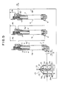
- a flow channel switching unit 11 is disposed to the ionized water discharge channel 9a ⁇ at the final stage of the serially connected ionized water discharge channels (9a in the drawing) and to the ionized water discharge channels 9b ⁇ on the other side after they are joined. It is of course possible to dispose the flow channels switching unit 11 to every ionized channels 9a, 9b for each of the electrolysis units 1a, 1b, 1c.
- the flow channel switching valve 11 comprises, for example, as shown in Figure 3 a cylindrical casing 14 containing a pair of introduction portions 12a, 12b for connection with the discharge channels 9a ⁇ , 9b ⁇ respectively and water discharge pipes 13a, 13b for separately discharging alkaline water and acidic water respectively and a flow channel switching slide valve 15 fitted in a liquid-sealing and slidable manner to the inside thereof.
- the paired introduction portions 12a, 12b are disposed with a axial gap of the casing 14.
- the water discharge pipe 13a of the paired discharge pipes 13a, 13b is disposed at a position between the introduction portions 12a, 12b, while the other water discharge pipe 13b is biforkate at the junction with the casing 14 and the forked branches 13b(1), 13b(2) are in communication with the ends of the casing 14 respectively.
- the slide valve 15 comprises a rod 15a and two valve bodies 15b, 15c secured thereto at a predetermined distance with each other.
- the valve bodies 15b and 15c are disposed in such a positional relationship that the communication of the introduction portions 12a and 12b are switched upon reciprocal movement of the slide valve 15 from the communication state with the one water discharge pipe 13a to the communication state with the other water discharge pipe 13b by way of the casing end alternately in an interlocked manner.
- the slide valve 15 may be driven manually, it is preferably actuated by a driving device 16 as shown in the drawing by using a motor 16a. Further, a detector 17 such as a limit switch may be disposed near the slide valve 15 for detecting the position of the valve 15 and controlling the motor 16a by the detection signal. Further, the motor 16a may be interlocked with the polarity changing switch 10a for the electrolysis units 1a, 1b, 1c so that the flow channel in the flow channel switching valve device 11 can be switched upon voltage polarity changing of the electrolysis unit 1 (or vice versa).
- the top end of the slide valve 15 and the motor 16a are connected by way of a crank 16b and a cam 16c so that the slide valve 15 can be driven reciprocately by the electric driving, as well as a detector 17 such as a limit switch is disposed near the crank 16b for detecting the position of the slide valve 15.
- the driving means is not necessarily restricted only to the embodiment shown in the drawing but it may be actuated by a solenoid or the like.
- the polarity changing switch 10a and the flow channel switching valve device 11 may be switched automatically on every predetermined of time by using a timer.
- a flow rate ratio control unit 18 may be disposed to the pair of the ionized water discharge channels 9a, 9b (or 9a ⁇ , 9b ⁇ ) of the water electrolyzing apparatus according to the present invention for adjusting the ratio of the flow rate between both of the discharge channels thereby controlling the pH value of the water formed by electrolysis.
- the flow rate ratio control device may comprise, for example, as shown in Figure 3, a valve case 20 having two channels 19a, 19b for connection with a pair of ionized water discharge channels 9a ⁇ , 9b ⁇ , and coaxial type valve 22 tightly fitted to the valve casing 20, and having a pair of through holes 21a, 21b formed at different angles to the direction of the corresponding discharge water channels formed corresponding to the two channels 19a, 19b.
- the rotary type valve 22 may be replaced with such a structure, not illustrated, that a slide valve body having a pair of through holes or valves displaced slightly from the gap between the two channels 19a, 19b is slidably fitted to the inside of the casing, so that the flow rate ratio between the channels 19a, 19b is adjusted by moving the slide valve body axially at the inside of the valve casing.
- a parallel-axis type flow rate ratio control valve as shown in Figure 4, comprising a pair of outer teethed rotary valve bodies 24a, 24b having lateral channels 23a, 23b respectively corresponding to the discharge channels 9a, 9b in which the respective valve bodies are engaged with each other in a manner capable of interlocking by way of peripheral gears such that the respective valve body channels 23a, 23b may take different angular positions to the pipeway direction of the corresponding discharge channels 9a, 9b.
- any two interlocking valve mechanisms may be used so as long as they are adapted such that when one of them is actuated in the direction of increasing the opening degree, for example, of the alkaline water discharge channel 9a ⁇ , the other of them is driven to restrict the opening degree for the acidic water discharge channel 9 ⁇ in view of the positional relationship with the pipeway direction of the respective discharge channels 9a, 9b ⁇ .
- the flow rate ratio control device 18 is disposed to the ionized water discharge channels 9a ⁇ , 9b ⁇ at the final stage, it may be disposed to the electrolyzed water discharge channel 9a, 9b for each of the electrolytic units 1a, 1b, 1c as shown by the phantom line in Figure 3.
- a 2-stage flow switch valve 25 capable of generating ON-OFF signals may be disposed to the pair of electrolyzed water discharge channels 9a ⁇ , 9b ⁇ .
- the 2-stage flow switch valve 25 illustrated in Figure 3 comprises two systems of channels 26a, 26b for communication with the pair of discharge channels 9a ⁇ , 9b ⁇ , valve seats 27a, 27b disposed for opening/closing the respective channels 26a, 26b, which are contained in a valve casing 28, a diaphragm 29 disposed in one of the channels and moved vertically by hydraulic pressure in the channel, a valve rod 30 integrally secured to the diaphragm 29 and passing through the two channels 26a, 26b, a main valve body 31a and a following valve body 31b secured integrally to the valve rod 30 for simultaneously opening/closing the two valve seats 27a, 27b, so that the two systems channels 26a, 26b are opened/closed simultaneously by the two valve bodies 31a, 31b of the valve rod 30 moved integrally with the diaphragm 29.
- a water passing channel 34 is formed in the valve rod 30 for communicating the chamber 29 ⁇ above the diaphragm 29 with the channel 26a downstream to the main valve body 27b and adapted so that when a cock on the side of taking out water is turned ON and OFF, the pressure in the chamber 29 ⁇ above the diaphragm 29 varies depending on the movement of the water by way of the water supply channel 34 to thereby actuate the diaphragm 29.
- a magnet 32 is attached on one side of the valve rod 30, whereas an ON-OFF signal generation device 33 such as a lead switch for generating signals upon approaching and aparting of the magnet 32 is mounted on the opposite side, so that the operation of the electrolyzing voltage circuit 10 can be controlled by the electrolysis unit.
- an ON-OFF signal generation device 33 such as a lead switch for generating signals upon approaching and aparting of the magnet 32 is mounted on the opposite side, so that the operation of the electrolyzing voltage circuit 10 can be controlled by the electrolysis unit.
- FIG. 5 illustrates a further embodiment in which a flow valve switch 25 is assembled into the electrolysis apparatus having the fundamental constitution according to the present invention.
- This embodiment is adapted such that water supplied as the starting material to the primary electrolysis unit 1a is introduced by way of the channel 26a of the 2-stage flow switch valve 25 on the side of the main valve body 31a (the channel on the side of disposing the diaphragm), as well as the acidic water from the electrolysis units 1a, 1b, 1c is discharged passing through the channel 26b of the flow switch valve 25 on the side of the following valve body 31b. Since the alkali water is not passed through the flow switch valve 25 in this structure, the flow switch valve free from the effect of calcium deposited in the alkaline water.
- the magnetic supply device 35 may be structured by disposing a coil unit 35a forming magnetic fields by electric current to the outside of the electrolysis vessel 7 as shown in Figure 3. Further, permanent magnets 35b may be disposed instead of them.
- the permanent magnet 35b as the magnetic supply device 35 may be disposed to the inside of the electrolysis vessel 7.
- the electrode 3 itself in the electrolysis vessel 7 may be constituted with a permanent magnet 35b or, as shown in Figure 6c, the inner electrode 3 is made tubular, and the permanent magnet 35b may be incorporated to the inside thereof.
- each of the two outer magnets 35b-2 is disposed so as to overriding the two adjacent inner magnets 35b-1, since the magnetic force can uniformly exerted in the longitudinal direction of the electrode chamber.
- the longitudinal distance D of the inner or the outer magnets is made greater than the distance d between the inner magnet 35b-1 and the outer magnet 35b-2. If the longitudinal distance of the magnets is shorter than that between the inner and the outer magnets, the larger magnetic force is exerted in the longitudinal direction to reduce the efficiency of the magnetic effect on the electrode chambers 5, 6.
- an electron-inducing high DC or AC voltage generating device 36 having an output terminal 36b for one pole being insulated is disposed to a portion or all of a plurality of electrolysis units 1a, 1b, 1c used in the apparatus according to the present invention, in addition to the electric circuit 10 for applying electrolysis voltage, and the output terminal for the other pole of the high voltage generation circuit 36, that is, the non-insulation side terminal is electrically connected by way of an electro-conductor to the inner electrode 3 in the electrolysis vessel 7 thereby inducing electrons e ⁇ to the water in the electrolysis vessel 7.
- the voltage applied in this case from the high voltage generation unit 36 is as high as from about 300 to about 10,000 V.
- the voltage applied for electron induction is not determined uniformly depending on the distance between both of the electrodes 2, 3 in the electrolysis vessel 7. That is, if the voltage applied is too high relative to the distance between both of the electrodes 2 and 3, the electrodes, will be short-circuitted failing to obtain the purpose. Accordingly, the voltage of the high voltage generation unit 36 is set to such a suitable level depending on the distance between the electrodes 2,3 so as not to short-circuit the electrodes but effectively induce electrons e ⁇ .
- the present invention also includes the case of connecting the discharging channels on the side of acidic water in series.
- the latter case can be used in the case of electrolyzing acidic water obtained from the electrolysis at the preceeding stage further into alkaline water and acidic water thereby increasing the amount of the alkaline water.
- the acidic ingredient is removed from alkali water on every electrolyzing process in the electrolyzing units and, accordingly, water at high alkali concentration can gradually be obtained to form alkaline water at high concentration.
- the present invention can also be utilized for the purification of underground water contaminated with fertilizers.
- cleaning for calcium deposited in the electrolysis vessel can be conducted automatically along with the continuous conduction for the electrolysis by switching the voltage polarity of the electrodes. If the flow channel switching unit 16 is used together, since the water is discharged from a predetermined water taking out port irrespective of the polarity switching in the electrolysis unit, there is no worry of mistaking the alkaline water and the acidic water to each other at the water taking out port.
- the magnetic generation device 35 is incorporated in the apparatus according to the present invention and the magnetic force is exerted on water during electrolysis from the magnetic generation device, water is easily put under the magnetic effect and it is possible to effectively produce magnetized ionized water and the ion permeation state through the diaphragm can be controlled in various ways since water is electrolyzed under the effect of magnetic force.
- the ion hydration due to electrolysis and physiological activation due to magnetization can be interacted advantageously with each other.
- a high voltage generation unit 36 insulated at one output terminal is disposed to the electrolysis unit of the apparatus according to the present invention and a high voltage (for instance 100 - 5000 V) is applied from the high voltage generation unit to the electrode of the electrolysis vessel, electrons are induced into the electrolysis vessel. Accordingly, since electrolyzed water is improved into water containing more electrons e ⁇ , water desirable for keeping health can be obtained, as well as ionized state such as of calcium, etc. in the ionized alkaline water can be maintained for a long period of time due to the presence of electrons e ⁇ thereby promoting the replacement with iron ion (Fe) in the iron pipes to retain the generation of rusts. Further, since the gaseous ingredients in the electrolyzed water are also ionized upon receiving electrons e ⁇ , it can also prevent the occurrence of rusts in the iron pipes due to oxygens, etc.
- a high voltage for instance 100 - 5000 V
Landscapes
- Chemical & Material Sciences (AREA)
- Chemical Kinetics & Catalysis (AREA)
- Electrochemistry (AREA)
- General Chemical & Material Sciences (AREA)
- Life Sciences & Earth Sciences (AREA)
- Hydrology & Water Resources (AREA)
- Engineering & Computer Science (AREA)
- Environmental & Geological Engineering (AREA)
- Water Supply & Treatment (AREA)
- Organic Chemistry (AREA)
- Water Treatment By Electricity Or Magnetism (AREA)
Applications Claiming Priority (2)
| Application Number | Priority Date | Filing Date | Title |
|---|---|---|---|
| JP5568387 | 1987-03-11 | ||
| JP55683/87 | 1987-03-11 |
Publications (3)
| Publication Number | Publication Date |
|---|---|
| EP0286233A2 true EP0286233A2 (de) | 1988-10-12 |
| EP0286233A3 EP0286233A3 (en) | 1989-01-11 |
| EP0286233B1 EP0286233B1 (de) | 1992-01-02 |
Family
ID=13005699
Family Applications (1)
| Application Number | Title | Priority Date | Filing Date |
|---|---|---|---|
| EP19880301961 Expired EP0286233B1 (de) | 1987-03-11 | 1988-03-07 | Wasserelektrolyse-Vorrichtung |
Country Status (2)
| Country | Link |
|---|---|
| EP (1) | EP0286233B1 (de) |
| DE (1) | DE3867284D1 (de) |
Cited By (16)
| Publication number | Priority date | Publication date | Assignee | Title |
|---|---|---|---|---|
| EP0396107A3 (de) * | 1989-05-02 | 1993-01-13 | Inax Corporation | Vorrichtung zum Einstellen einer Ionenkonzentration für ionisiertes Wasser |
| WO1993020014A1 (fr) * | 1992-04-03 | 1993-10-14 | Bakhir Vitold M | Dispositif concernant le traitement elecrochimique de l'eau |
| EP0605882A1 (de) * | 1993-01-08 | 1994-07-13 | Nec Corporation | Verfahren und Vorrichtung zur Nassbehandlung von festen Oberflächen |
| EP0702400A3 (de) * | 1992-05-29 | 1996-05-15 | Texas Instruments Inc | Entfernung von Metall-Kontamination |
| US5695569A (en) * | 1991-02-28 | 1997-12-09 | Texas Instruments Incorporated | Removal of metal contamination |
| US5695570A (en) * | 1991-02-28 | 1997-12-09 | Texas Instruments Incorporated | Method for the photo-stimulated removal of trace metals from a semiconductor surface |
| WO1998027012A1 (fr) * | 1996-12-14 | 1998-06-25 | Western Pacific | Procede de traitement electrochimique de solutions aqueuses et dispositif de mise en oeuvre de ce procede |
| WO1998050309A1 (en) * | 1996-03-27 | 1998-11-12 | Bakhir Vitold M | Apparatus for electrochemical treatment of water and/or water solutions |
| RU2133223C1 (ru) * | 1998-04-30 | 1999-07-20 | Рамазанов Зуфар Джалилович | Установка для электрохимической очистки воды |
| RU2141454C1 (ru) * | 1998-04-29 | 1999-11-20 | Бахир Витольд Михайлович | Установка для электрохимической обработки воды и/или водных растворов |
| RU2141453C1 (ru) * | 1995-06-30 | 1999-11-20 | Товарищество с ограниченной ответственностью "Лаборатория электрохимической технологии" | Устройство для электрохимической обработки воды и водных растворов |
| RU2142427C1 (ru) * | 1998-10-12 | 1999-12-10 | Габленко Вячеслав Георгиевич | Устройство для электрохимической обработки воды и водных растворов |
| RU2157793C1 (ru) * | 1999-02-01 | 2000-10-20 | Бахир Витольд Михайлович | Способ получения дезинфицирующего раствора - нейтрального анолита |
| RU2169120C1 (ru) * | 2000-09-27 | 2001-06-20 | Закрытое акционерное общество Производственное объединение "Джет" | Устройство для электрохимической обработки воды |
| RU2211806C2 (ru) * | 2001-07-02 | 2003-09-10 | Закрытое акционерное общество Производственное объединение "Джет" | Устройство для электрохимической обработки воды |
| WO2004007376A1 (en) * | 2002-07-17 | 2004-01-22 | Peter Nunn | Water treatment device for electrolyzing, magnetizing, and re-resonating water |
Family Cites Families (5)
| Publication number | Priority date | Publication date | Assignee | Title |
|---|---|---|---|---|
| US1840105A (en) * | 1928-03-15 | 1932-01-05 | Gen Zeolite Company | Liquid purification |
| US2794776A (en) * | 1954-03-16 | 1957-06-04 | Robert E Briggs | Water purification process |
| GB1162212A (en) * | 1966-04-25 | 1969-08-20 | Const John Brown Ltd | An Electrolytic Method for the Purification of Sewage or like Effluents |
| GB1184580A (en) * | 1967-07-18 | 1970-03-18 | Kenjiro Yanagase | Electrolysis of Sea Water to Produce Chlorine Gas and Dissolved Chlorine. |
| DE2329630C3 (de) * | 1973-06-09 | 1980-04-10 | Sachs Systemtechnik Gmbh, 8720 Schweinfurt | Verfahren und Einrichtung zur Entkeimung von Flüssigkeiten durch anodische Oxydation mit vorheriger Reduktion |
-
1988
- 1988-03-07 EP EP19880301961 patent/EP0286233B1/de not_active Expired
- 1988-03-07 DE DE8888301961T patent/DE3867284D1/de not_active Expired - Fee Related
Cited By (20)
| Publication number | Priority date | Publication date | Assignee | Title |
|---|---|---|---|---|
| EP0396107A3 (de) * | 1989-05-02 | 1993-01-13 | Inax Corporation | Vorrichtung zum Einstellen einer Ionenkonzentration für ionisiertes Wasser |
| US5695569A (en) * | 1991-02-28 | 1997-12-09 | Texas Instruments Incorporated | Removal of metal contamination |
| US5695570A (en) * | 1991-02-28 | 1997-12-09 | Texas Instruments Incorporated | Method for the photo-stimulated removal of trace metals from a semiconductor surface |
| WO1993020014A1 (fr) * | 1992-04-03 | 1993-10-14 | Bakhir Vitold M | Dispositif concernant le traitement elecrochimique de l'eau |
| GB2274113A (en) * | 1992-04-03 | 1994-07-13 | Bakhir Vitold M | Apparatus for electrochemical treatment of water |
| US5427667A (en) * | 1992-04-03 | 1995-06-27 | Bakhir; Vitold M. | Apparatus for electrochemical treatment of water |
| GB2274113B (en) * | 1992-04-03 | 1996-05-15 | Bakhir Vitold M | Apparatus for electrochemical treatment of water |
| EP0702400A3 (de) * | 1992-05-29 | 1996-05-15 | Texas Instruments Inc | Entfernung von Metall-Kontamination |
| EP0605882A1 (de) * | 1993-01-08 | 1994-07-13 | Nec Corporation | Verfahren und Vorrichtung zur Nassbehandlung von festen Oberflächen |
| US5578193A (en) * | 1993-01-08 | 1996-11-26 | Nec Corporation | Method and apparatus for wet treatment of solid surfaces |
| RU2141453C1 (ru) * | 1995-06-30 | 1999-11-20 | Товарищество с ограниченной ответственностью "Лаборатория электрохимической технологии" | Устройство для электрохимической обработки воды и водных растворов |
| WO1998050309A1 (en) * | 1996-03-27 | 1998-11-12 | Bakhir Vitold M | Apparatus for electrochemical treatment of water and/or water solutions |
| WO1998027012A1 (fr) * | 1996-12-14 | 1998-06-25 | Western Pacific | Procede de traitement electrochimique de solutions aqueuses et dispositif de mise en oeuvre de ce procede |
| RU2141454C1 (ru) * | 1998-04-29 | 1999-11-20 | Бахир Витольд Михайлович | Установка для электрохимической обработки воды и/или водных растворов |
| RU2133223C1 (ru) * | 1998-04-30 | 1999-07-20 | Рамазанов Зуфар Джалилович | Установка для электрохимической очистки воды |
| RU2142427C1 (ru) * | 1998-10-12 | 1999-12-10 | Габленко Вячеслав Георгиевич | Устройство для электрохимической обработки воды и водных растворов |
| RU2157793C1 (ru) * | 1999-02-01 | 2000-10-20 | Бахир Витольд Михайлович | Способ получения дезинфицирующего раствора - нейтрального анолита |
| RU2169120C1 (ru) * | 2000-09-27 | 2001-06-20 | Закрытое акционерное общество Производственное объединение "Джет" | Устройство для электрохимической обработки воды |
| RU2211806C2 (ru) * | 2001-07-02 | 2003-09-10 | Закрытое акционерное общество Производственное объединение "Джет" | Устройство для электрохимической обработки воды |
| WO2004007376A1 (en) * | 2002-07-17 | 2004-01-22 | Peter Nunn | Water treatment device for electrolyzing, magnetizing, and re-resonating water |
Also Published As
| Publication number | Publication date |
|---|---|
| DE3867284D1 (de) | 1992-02-13 |
| EP0286233A3 (en) | 1989-01-11 |
| EP0286233B1 (de) | 1992-01-02 |
Similar Documents
| Publication | Publication Date | Title |
|---|---|---|
| US4810344A (en) | Water electrolyzing apparatus | |
| EP0286233A2 (de) | Wasserelektrolyse-Vorrichtung | |
| CN1105083C (zh) | 一种液体净化装置 | |
| US5468378A (en) | Magnetic conditioners for treating liquids | |
| US3728245A (en) | Apparatus for treating sewage | |
| EP0374942B1 (de) | Gas-Flüssigkeitstrennungsverfahren und Vorrichtung für zweiphasige elektroleitende Gas-Flüssigkeitsströme | |
| US3092566A (en) | Sterilization and purification apparatus | |
| EP0128782A1 (de) | Wasserreinigungsgerät | |
| EP0408229A1 (de) | Vorrichtung für die kontinuierliche Erzeugung von elektrolysiertem Wasser | |
| SU1528737A1 (ru) | Устройство дл электромагнитной коагул ции жидкости | |
| JP2002263655A (ja) | 磁気処理水生成装置および液体燃料磁気処理装置 | |
| JPH01104387A (ja) | 水の電解装置 | |
| JPH01111483A (ja) | 電子を多く含んだ電解水の生成装置 | |
| JPH01135584A (ja) | 電解イオン水生成装置 | |
| CN203373232U (zh) | 一种水净化器 | |
| JP3569545B2 (ja) | 電解水生成装置及び電解水の水質測定方法 | |
| SU1745687A1 (ru) | Аппарат дл электрохимической обработки жидкости | |
| JPH03188A (ja) | 磁化イオン水の生成方法及び装置 | |
| KR20060079643A (ko) | 전해장치 및 자화장치를 이용한 자화 이온수기 | |
| KR20000006771A (ko) | 활성정수의 멸균장치 및 그 제조방법. | |
| KR20220001342U (ko) | 토션장을 이용한 기능성 전해수 생성장치 | |
| JPH05115881A (ja) | 水酸化銀含有アルカリ電解水生成装置 | |
| JP2004122108A (ja) | 電解還元水の生成装置 | |
| JPH01207188A (ja) | 電解イオン水生成装置 | |
| JPH0647378A (ja) | イオン水生成器 |
Legal Events
| Date | Code | Title | Description |
|---|---|---|---|
| PUAI | Public reference made under article 153(3) epc to a published international application that has entered the european phase |
Free format text: ORIGINAL CODE: 0009012 |
|
| AK | Designated contracting states |
Kind code of ref document: A2 Designated state(s): DE FR GB IT NL |
|
| PUAL | Search report despatched |
Free format text: ORIGINAL CODE: 0009013 |
|
| AK | Designated contracting states |
Kind code of ref document: A3 Designated state(s): DE FR GB IT NL |
|
| 17P | Request for examination filed |
Effective date: 19890621 |
|
| 17Q | First examination report despatched |
Effective date: 19900502 |
|
| GRAA | (expected) grant |
Free format text: ORIGINAL CODE: 0009210 |
|
| AK | Designated contracting states |
Kind code of ref document: B1 Designated state(s): DE FR GB IT NL |
|
| PG25 | Lapsed in a contracting state [announced via postgrant information from national office to epo] |
Ref country code: NL Effective date: 19920102 |
|
| ITF | It: translation for a ep patent filed | ||
| REF | Corresponds to: |
Ref document number: 3867284 Country of ref document: DE Date of ref document: 19920213 |
|
| EN | Fr: translation not filed | ||
| PG25 | Lapsed in a contracting state [announced via postgrant information from national office to epo] |
Ref country code: FR Effective date: 19920522 |
|
| NLV1 | Nl: lapsed or annulled due to failure to fulfill the requirements of art. 29p and 29m of the patents act | ||
| PLBE | No opposition filed within time limit |
Free format text: ORIGINAL CODE: 0009261 |
|
| STAA | Information on the status of an ep patent application or granted ep patent |
Free format text: STATUS: NO OPPOSITION FILED WITHIN TIME LIMIT |
|
| 26N | No opposition filed | ||
| REG | Reference to a national code |
Ref country code: FR Ref legal event code: ST |
|
| PGFP | Annual fee paid to national office [announced via postgrant information from national office to epo] |
Ref country code: GB Payment date: 19950228 Year of fee payment: 8 |
|
| PGFP | Annual fee paid to national office [announced via postgrant information from national office to epo] |
Ref country code: DE Payment date: 19950325 Year of fee payment: 8 |
|
| PG25 | Lapsed in a contracting state [announced via postgrant information from national office to epo] |
Ref country code: GB Effective date: 19960307 |
|
| GBPC | Gb: european patent ceased through non-payment of renewal fee |
Effective date: 19960307 |
|
| PG25 | Lapsed in a contracting state [announced via postgrant information from national office to epo] |
Ref country code: DE Effective date: 19961203 |
|
| PG25 | Lapsed in a contracting state [announced via postgrant information from national office to epo] |
Ref country code: IT Free format text: LAPSE BECAUSE OF NON-PAYMENT OF DUE FEES;WARNING: LAPSES OF ITALIAN PATENTS WITH EFFECTIVE DATE BEFORE 2007 MAY HAVE OCCURRED AT ANY TIME BEFORE 2007. THE CORRECT EFFECTIVE DATE MAY BE DIFFERENT FROM THE ONE RECORDED. Effective date: 20050307 |