EP0282641B1 - Beleuchtungssystem zur Beleuchtung des Passagierraumes von Aufzugskabinen - Google Patents
Beleuchtungssystem zur Beleuchtung des Passagierraumes von Aufzugskabinen Download PDFInfo
- Publication number
- EP0282641B1 EP0282641B1 EP87116489A EP87116489A EP0282641B1 EP 0282641 B1 EP0282641 B1 EP 0282641B1 EP 87116489 A EP87116489 A EP 87116489A EP 87116489 A EP87116489 A EP 87116489A EP 0282641 B1 EP0282641 B1 EP 0282641B1
- Authority
- EP
- European Patent Office
- Prior art keywords
- illumination
- lamp
- lighting device
- displays
- exit
- Prior art date
- Legal status (The legal status is an assumption and is not a legal conclusion. Google has not performed a legal analysis and makes no representation as to the accuracy of the status listed.)
- Expired - Lifetime
Links
Images

Classifications
-
- B—PERFORMING OPERATIONS; TRANSPORTING
- B66—HOISTING; LIFTING; HAULING
- B66B—ELEVATORS; ESCALATORS OR MOVING WALKWAYS
- B66B11/00—Main component parts of lifts in, or associated with, buildings or other structures
- B66B11/02—Cages, i.e. cars
- B66B11/0226—Constructional features, e.g. walls assembly, decorative panels, comfort equipment, thermal or sound insulation
- B66B11/0233—Lighting systems
Definitions
- the invention relates to a lighting device for illuminating a passenger compartment of elevator cars.
- Such devices enable safe entry into the passenger compartment and operation of the elevator system before the journey, visual communication among the passengers during the journey and safe and orderly exit from the passenger compartment after the journey.
- a lighting device according to CH-PS 241 497 is known, in which a tubular light source is arranged vertically above the cabin entrance / exit.
- the arrangement of the light source on the cabin ceiling in accordance with CH-PS 241 497 has the disadvantage that, despite the tubular light source, the cabin panel is in the shadow of the passengers when the elevator car is fully occupied.
- Another disadvantage of the known device lies in the increased outlay in labor and material due to the ceiling mounting of the lighting device.
- the known device and its arrangement result in an impairment of the aesthetic nature of the passenger compartment interior.
- a lighting device in which a plurality of lights with tubular fluorescent lamps are integrated in the ceiling of an elevator car.
- the lighting fixtures of the lights are arranged on ceiling brackets.
- Matted covers arranged on a suspended and height-adjustable frame are provided as a ceiling finish, which scatter the light emitted by the tubular light sources.
- the disadvantage of the lighting device mentioned is that an elaborate ceiling construction is necessary due to the dimensions of the lights, which makes increased work and material inevitable. There are also additional electrical installation work. Another disadvantage of the known device is that the aesthetic design of the cabin ceiling is difficult because of the large covers of the lights.
- the invention seeks to remedy this.
- the invention as characterized in the claims, solves the problem of creating a lighting system for illuminating a passenger compartment of elevator cars, which is suitable for installation in existing recesses.
- the advantages achieved by the invention can be seen essentially in the fact that the installation of the lighting system in existing cabin wall recesses Ceiling construction of the elevator car is simplified to the extent that recesses in the ceiling for receiving lighting fixtures or ceilings suspended in integral lighting systems are no longer required.
- the wiring of the lighting system according to the invention can be included in the pre-wiring of the control elements housed in the cabin wall recess.
- Another advantage of the invention is that the air displacement triggered by the upward / downward movement of the elevator car serves to vent the lighting system.
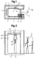
- 1 denotes a lift shaft delimited by a shaft wall 1.1 and shaft sliding doors 1.2.
- a counterweight 2 and an elevator car 3 with car sliding doors 3.1, car walls 3.2, a car ceiling 3.3 and a car floor 3.4 are guided in it.
- a mounting duct 3.5 is embedded in a cabin wall 3.2 and is delimited by a duct cover 3.6 and a duct wall 3.7.
- the mounting channel 3.5 serves to accommodate a cabin panel 3.8 and a lighting system 4.
- the latter has a transparent cover surface 4.1, which is held with a surround 4.11 becomes.
- the lighting system also includes 4 lights 4.2; 4.3, which essentially consists of light sources 4.21; 4.31, reflectors 4.22; 4.32 and a bracket 4.4 exist.
- the mounting channel 3.5 has openings at the top and bottom. Passengers 6 enter or leave a passenger space 7 via an elevator entrance / exit 8.
- the lighting system 4 Thanks to the compact design of the lighting system 4 according to the invention, it has become possible to integrate it into the mounting channel 3.5, which is usually present and accommodates the cage and control elements. Despite the recessed installation and arrangement in the cabin wall 3.2, the lighting system 4 guarantees complete illumination of the passenger compartment 7. It is indirectly illuminated on the one hand by the cabin ceiling 3.3 illuminated by the lower lamp 4.2, and on the other hand by the upper lamp 4.3 in the vicinity of the cabin panel 3.8 and the Elevator entrance / exit 8 directly illuminated. Both lights 4.2; 4.3 are with reflectors 4.22; 4.32 equipped with the light distribution curves necessary to achieve optimal lighting. As light sources 4.21; 4.31 halogen or discharge lamps with the corresponding light outputs are provided.
Landscapes
- Engineering & Computer Science (AREA)
- Civil Engineering (AREA)
- Mechanical Engineering (AREA)
- Structural Engineering (AREA)
- Cage And Drive Apparatuses For Elevators (AREA)
- Elevator Control (AREA)
Description
- Die Erfindung betrifft eine Beleuchtungseinrichtung zur Beleuchtung eines Passagierraumes von Aufzugskabinen.
- Solche Einrichtungen ermöglichen vor der Fahrt ein sicheres Betreten des Passagierraumes und Bedienen der Aufzugsanlage, während der Fahrt eine visuelle Kommunikation unter den Passagieren und nach der Fahrt ein sicheres, geordnetes Verlassen des Passagierraumes.
- Es ist eine Beleuchtungseinrichtung gemäss CH-PS 241 497 bekannt, bei der eine rohrförmige Lichtquelle senkrecht über dem Kabinen-Ein-/Ausgang angeordnet ist.
- Die Anordnung der Lichtquelle an der Kabinendecke gemäss CH-PS 241 497 hat den Nachteil, dass trotz rohrförmiger Lichtquelle das Kabinentableau bei vollbesetzter Aufzugskabine im Schatten der Passagiere liegt. Ein weiterer Nachteil der bekannten Einrichtung liegt in dem durch die Deckenmontage der Beleuchtungseinrichtung bedingten, vermehrten Aufwand an Arbeit und Material. Hinzu kommt, dass durch die bekannte Einrichtung und deren Anordnung eine Beeinträchtigung ästhtischer Art des Passagierrauminterieurs entsteht.
- Es ist eine Beleuchtungseinrichtung gemäss US-A-4 126 210 bekannt, bei der mehrere Leuchten mit rohrförmigen Leuchtstofflampen in der Decke einer Aufzugskabine integriert sind. Die Beleuchtungskörper der Leuchten sind an Deckenträgern angeordnet. Als Deckenabschluss sind mattierte an einem heruntergehängten und in der Höhe verstellbaren Rahmen angeordnete Abdeckungen vorgesehen, die das von den rohrförmigen Lichtquellen ausgesandte Licht streuen.
- Der Nachteil der genannten Beleuchtungseinrichtung liegt darin, dass eine durch die Abmessungen der Leuchten bedingte aufwendige Deckenkonstruktion notwendig ist, die einen vermehrten Aufwand an Arbeit und Material unumgänglich macht. Hinzu kommen zusätzliche Elektroinstallationsarbeiten. Ein weiterer Nachteil der bekannten Einrichtung liegt darin, dass wegen den grossflächigen Abdeckungen der Leuchten die ästhetische Gestaltung der Kabinendecke erschwert wird.
- Hier will die Erfindung Abhilfe schaffen. Die Erfindung, wie sie in den Ansprüchen gekennzeichnet ist, löst die Aufgabe, ein Beleuchtungssystem zur Beleuchtung eines Passagierraumes von Aufzugskabinen zu schaffen, das sich zum Einbau in bestehende Ausnehmungen eignet.
- Die durch die Erfindung erreichten Vorteile sind im wesentlichen darin zu sehen, dass der Einbau des Beleuchtungssystems in bestehende Kabinenwandausnehmungen die Deckenkonstruktion der Aufzugskabine insoweit vereinfacht, als Ausnehmungen in der Decke zur Aufnahme von Beleuchtungskörpern oder bei integralen Beleuchtungssystemen heruntergehängte Decken entfallen. Ausserdem lässt sich die Verkabelung des erfindungsgemässen Beleuchtungssystems in die Vorverkabelung der in der Kabinenwandausnehmung untergebrachten Steuerorgane miteinbeziehen. Ein weiterer Vorteil der Erfindung besteht darin, dass die durch die Aufwärts-/Abwärtsbewegung der Aufzugskabine ausgelöste Luftverdrängung der Belüftung des Beleuchtungssystems dient.
- Im folgenden wird die Erfindung anhand von lediglich einen Ausführungsweg darstellenden Zeichnungen näher erläutert. Es zeigen:
- Fig. 1
- einen Grundriss einer in einem Aufzugsschacht geführten, mit einem Montagekanal versehenen Aufzugskabine bei Stockwerkhalt,
- Fig. 2
- einen Aufriss eines Passagierraumes einer Aufzugskabine mit einem erfindungsgemässen Beleuchtungssystem und
- Fig. 3
- einen Aufbau des Beleuchtungssystems und dessen Anordnung in einem Montagekanal.
- In den Fig. 1 bis 3 ist mit 1 ein durch eine Schachtwand 1.1 und Schachtschiebetüren 1.2 abgegrenzter Liftschacht bezeichnet. In ihm wird ein Gegengewicht 2 sowie eine Aufzugskabine 3 mit Kabinenschiebetüren 3.1, Kabinenwänden 3.2, einer Kabinendecke 3.3 und einem Kabinenboden 3.4 geführt. In einer Kabinenwand 3.2 ist ein Montagekanal 3.5 eingelassen, der durch eine Kanalabdeckung 3.6 und einer Kanalwand 3.7 abgegrenzt ist. Der Montagekanal 3.5 dient zur Aufnahme eines Kabinentableaus 3.8 und eines Beleuchtungssystems 4. Letzteres weist eine transparente Deckfläche 4.1 auf, die mit einer Umfassung 4.11 gehalten wird. Ausserdem gehören dem Beleuchtungssystem 4 Leuchten 4.2; 4.3 an, die im wesentlichen aus Lichtquellen 4.21; 4.31, Reflektoren 4.22; 4.32 und einem Haltebügel 4.4 bestehen. Mit 4.23 ist die Lichtabstrahlung der Leuchte 4.2, mit 4.33 ist die Lichtabstrahlung der Leuchte 4.3 bezeichnet. Zur Belüftung 5 des Beleuchtungssystems 4 weist der Montagekanal 3.5 oben und unten Öffnungen auf. Passagiere 6 betreten oder verlassen einen Passagierraum 7 über einen Aufzugs-Ein-/Ausgang 8.
- Dank der kompakten Bauweise des erfindungsgemässen Beleuchtungssystems 4 ist es möglich geworden, es in dem üblicherweise vorhandenen, Kablage und Steuerorgane aufnehmenden Montagekanal 3.5 zu integrieren. Trotz versenkter Einbauweise und Anordnung in der Kabinenwand 3.2 garantiert das Beleuchtungssystem 4 eine vollständige Ausleuchtung des Passagierraumes 7. Er wird einerseits von der von der unteren Leuchte 4.2 angestrahlten Kabinendecke 3.3 indirekt beleuchtet, andererseits von der oberen Leuchte 4.3 in der Umgebung des Kabinentableaus 3.8 und des Aufzugs-Ein-/Ausgangs 8 direkt beleuchtet. Beide Leuchten 4.2; 4.3 sind mit Reflektoren 4.22; 4.32 ausgerüstet, die die zur Erzielung einer optimalen Beleuchtung notwendigen Lichtverteilungskurven aufweisen. Als Lichtquellen 4.21; 4.31 sind Halogen- oder Entladungslampen mit den entsprechenden Lichtleistungen vorgesehen.
Claims (4)
- Beleuchtungseinrichtung zur Beleuchtung eines Passagierraumes (7) von Aufzugskabinen (3),
dadurch gekennzeichnet,- dass die Beleuchtungseinrichtung ein an einem in einer Kabinenwand (3.2) vertikal verlaufenden Montagekanal (3.5) angeordnetes Beleuchtungssystem (4) aufweist, das mit mindestens einer Leuchte (4.2; 4.3) zur direkten Beleuchtung der Umgebung von Kabinentableau (3.8) und Aufzugs- Ein-/Ausgang (8) und zur indirekten Beleuchtung des Passagierraumes (7) und mit einer transparenten Deckfläche (4.1) versehen ist, und- dass der Montagekanal (3.5) zur Belüftung (5) des Beleuchtungssystems (4) oben und unten Öffnungen aufweist. - Beleuchtungseinrichtung nach Anspruch 1,
dadurch gekennzeichnet,- dass das Beleuchtungssystem (4) mindestens eine Leuchte (4.2; 4.3) mit einer punktförmigen oder rohrförmigen Lichtquelle (4.21; 4.31) aufweist. - Beleuchtungseinrichtung nach Anspruch 1,
dadurch gekennzeichnet,- dass je Leuchte (4.2; 4.3) eine transparente Deckfläche (4.1) vorgesehen ist und- dass jede Leuchte (4.2; 4.3) unabhängig von der anderen angeordnet ist. - Beleuchtungseinrichtung nach Anspruch 1,
dadurch gekennzeichnet,- dass die Leuchte (4.2; 4.3) ein zur Lenkung des Lichtstromes der Lichtquellen (4.21; 4.31) vorgesehener Reflektor (4.22; 4.32) aufweist, der dergestalt ist, dass der gelenkte Lichtstrom zur direkten Beleuchtung der Umgebung von Kabinentableau (3.8) und Aufzugs-Ein-/Ausgang (8) und zur indirekten Beleuchtung des Passagierraumes (7) beiträgt.
Priority Applications (1)
| Application Number | Priority Date | Filing Date | Title |
|---|---|---|---|
| AT87116489T ATE63890T1 (de) | 1987-03-16 | 1987-11-09 | Beleuchtungssystem zur beleuchtung des passagierraumes von aufzugskabinen. |
Applications Claiming Priority (2)
| Application Number | Priority Date | Filing Date | Title |
|---|---|---|---|
| CH971/87 | 1987-03-16 | ||
| CH97187 | 1987-03-16 |
Publications (2)
| Publication Number | Publication Date |
|---|---|
| EP0282641A1 EP0282641A1 (de) | 1988-09-21 |
| EP0282641B1 true EP0282641B1 (de) | 1991-05-29 |
Family
ID=4199460
Family Applications (1)
| Application Number | Title | Priority Date | Filing Date |
|---|---|---|---|
| EP87116489A Expired - Lifetime EP0282641B1 (de) | 1987-03-16 | 1987-11-09 | Beleuchtungssystem zur Beleuchtung des Passagierraumes von Aufzugskabinen |
Country Status (4)
| Country | Link |
|---|---|
| EP (1) | EP0282641B1 (de) |
| AT (1) | ATE63890T1 (de) |
| DE (1) | DE3770455D1 (de) |
| ES (1) | ES2023393B3 (de) |
Families Citing this family (4)
| Publication number | Priority date | Publication date | Assignee | Title |
|---|---|---|---|---|
| ATE132113T1 (de) * | 1991-05-13 | 1996-01-15 | Inventio Ag | Aufzugskabine |
| ES2064197B1 (es) * | 1992-05-04 | 1997-02-01 | Otis Elevator Co | Perfeccionamientos en cabinas de ascensores. |
| FI96410C (fi) * | 1992-09-04 | 1996-06-25 | Kone Oy | Hissikorin seinärakenne ja hissikori |
| KR20050116605A (ko) * | 2004-06-08 | 2005-12-13 | 윤일식 | 엘리베이터 천정에 설치되는 조립식 조명반사시스템 |
Citations (1)
| Publication number | Priority date | Publication date | Assignee | Title |
|---|---|---|---|---|
| US4126210A (en) * | 1976-07-14 | 1978-11-21 | Westinghouse Electric Corp. | Elevator car with adjustable illumination level and distribution patterns |
Family Cites Families (2)
| Publication number | Priority date | Publication date | Assignee | Title |
|---|---|---|---|---|
| CH241497A (de) * | 1944-08-23 | 1946-03-15 | Inventio Ag | Beleuchtungseinrichtung in Aufzugskabine. |
| US3707205A (en) * | 1971-08-31 | 1972-12-26 | Otis Elevator Co | Elevator car with elements combining both structural and wiring housing functions |
-
1987
- 1987-11-09 AT AT87116489T patent/ATE63890T1/de not_active IP Right Cessation
- 1987-11-09 DE DE8787116489T patent/DE3770455D1/de not_active Expired - Fee Related
- 1987-11-09 EP EP87116489A patent/EP0282641B1/de not_active Expired - Lifetime
- 1987-11-09 ES ES87116489T patent/ES2023393B3/es not_active Expired - Lifetime
Patent Citations (1)
| Publication number | Priority date | Publication date | Assignee | Title |
|---|---|---|---|---|
| US4126210A (en) * | 1976-07-14 | 1978-11-21 | Westinghouse Electric Corp. | Elevator car with adjustable illumination level and distribution patterns |
Also Published As
| Publication number | Publication date |
|---|---|
| DE3770455D1 (de) | 1991-07-04 |
| ES2023393B3 (es) | 1992-01-16 |
| EP0282641A1 (de) | 1988-09-21 |
| ATE63890T1 (de) | 1991-06-15 |
Similar Documents
| Publication | Publication Date | Title |
|---|---|---|
| DE102010001777B4 (de) | Beleuchtungseinrichtung | |
| EP1059230B1 (de) | Funktionseinheit für Passagierkabinen, insbesondere für Flugzeugpassagierkabinen | |
| AU1491800A (en) | Machine-room-less elevator | |
| DE59907487D1 (de) | Doppeldecker- oder Multidecker-Aufzug | |
| EP1031527A1 (de) | Notbeleuchtung in Aufzugkabinen mit phosphoreszierenden Materialien. | |
| ES2064197B1 (es) | Perfeccionamientos en cabinas de ascensores. | |
| EP0282641B1 (de) | Beleuchtungssystem zur Beleuchtung des Passagierraumes von Aufzugskabinen | |
| DE102009013942A1 (de) | Fahrzeugsitz mit einer Beleuchtungseinrichtung | |
| EP1031445B1 (de) | Fahrzeug mit Klimakanal und Beleuchtungseinrichtung | |
| US20190084799A1 (en) | Lighting systems for elevator systems | |
| EP0282640B1 (de) | Beleuchtungssystem zur dekorativen Beleuchtung des Passagierraumes von Aufzugskabinen | |
| DE102006032249B4 (de) | Unsichtbare Notfallbeleuchtung für eine Luftfahrzeugkabine | |
| DE2635431A1 (de) | Beleuchtungsanlage fuer direkte und indirekte beleuchtung | |
| AU648408B2 (en) | Equipment for illumination of the passenger space of a lift cage | |
| WO2019086525A1 (de) | Aufzugskabine | |
| JPH0213590A (ja) | エレベータ乗かごの冷房装置 | |
| DE10208111B4 (de) | Innenbeleuchtungssystem für ein Flugzeug | |
| EP1020682A1 (de) | Decken-, Wand- oder Standleuchte für die Innenraumbeleuchtung | |
| CN110691750A (zh) | 电梯装置、电梯装置的维护方法及电梯装置的制造方法 | |
| DE102013005310A1 (de) | Vorrichtung zur Aufnahme von Produktions-Anlagen | |
| DE202009010844U1 (de) | Wartungsabdeckung, insbesondere Revisionsklappe | |
| EP2017215A1 (de) | Wandverkleidung und Aufzugskabinen mit einer solchen Wandverkleidung | |
| AT517745A2 (de) | Kombinierte Beleuchtungs- und Belüftungsvorrichtung | |
| DE10208109B4 (de) | Innenbeleuchtungssytem für einen Hubschrauber | |
| JPH02117586A (ja) | エレベータのかご室 |
Legal Events
| Date | Code | Title | Description |
|---|---|---|---|
| PUAI | Public reference made under article 153(3) epc to a published international application that has entered the european phase |
Free format text: ORIGINAL CODE: 0009012 |
|
| AK | Designated contracting states |
Kind code of ref document: A1 Designated state(s): AT CH DE ES FR GB IT LI |
|
| 17P | Request for examination filed |
Effective date: 19890211 |
|
| 17Q | First examination report despatched |
Effective date: 19900115 |
|
| GRAA | (expected) grant |
Free format text: ORIGINAL CODE: 0009210 |
|
| AK | Designated contracting states |
Kind code of ref document: B1 Designated state(s): AT CH DE ES FR GB IT LI |
|
| REF | Corresponds to: |
Ref document number: 63890 Country of ref document: AT Date of ref document: 19910615 Kind code of ref document: T |
|
| REF | Corresponds to: |
Ref document number: 3770455 Country of ref document: DE Date of ref document: 19910704 |
|
| ET | Fr: translation filed | ||
| GBT | Gb: translation of ep patent filed (gb section 77(6)(a)/1977) | ||
| ITF | It: translation for a ep patent filed |
Owner name: MODIANO & ASSOCIATI S.R.L. |
|
| REG | Reference to a national code |
Ref country code: ES Ref legal event code: FG2A Ref document number: 2023393 Country of ref document: ES Kind code of ref document: B3 |
|
| PLBE | No opposition filed within time limit |
Free format text: ORIGINAL CODE: 0009261 |
|
| STAA | Information on the status of an ep patent application or granted ep patent |
Free format text: STATUS: NO OPPOSITION FILED WITHIN TIME LIMIT |
|
| 26N | No opposition filed | ||
| PGFP | Annual fee paid to national office [announced via postgrant information from national office to epo] |
Ref country code: AT Payment date: 19951030 Year of fee payment: 9 |
|
| PGFP | Annual fee paid to national office [announced via postgrant information from national office to epo] |
Ref country code: CH Payment date: 19960220 Year of fee payment: 9 |
|
| PG25 | Lapsed in a contracting state [announced via postgrant information from national office to epo] |
Ref country code: AT Effective date: 19961109 |
|
| PG25 | Lapsed in a contracting state [announced via postgrant information from national office to epo] |
Ref country code: LI Effective date: 19961130 Ref country code: CH Effective date: 19961130 |
|
| REG | Reference to a national code |
Ref country code: CH Ref legal event code: PL |
|
| PGFP | Annual fee paid to national office [announced via postgrant information from national office to epo] |
Ref country code: DE Payment date: 19981021 Year of fee payment: 12 |
|
| PGFP | Annual fee paid to national office [announced via postgrant information from national office to epo] |
Ref country code: FR Payment date: 19981022 Year of fee payment: 12 |
|
| PGFP | Annual fee paid to national office [announced via postgrant information from national office to epo] |
Ref country code: GB Payment date: 19981028 Year of fee payment: 12 |
|
| PGFP | Annual fee paid to national office [announced via postgrant information from national office to epo] |
Ref country code: ES Payment date: 19981116 Year of fee payment: 12 |
|
| PG25 | Lapsed in a contracting state [announced via postgrant information from national office to epo] |
Ref country code: GB Free format text: LAPSE BECAUSE OF NON-PAYMENT OF DUE FEES Effective date: 19991109 |
|
| PG25 | Lapsed in a contracting state [announced via postgrant information from national office to epo] |
Ref country code: ES Free format text: LAPSE BECAUSE OF NON-PAYMENT OF DUE FEES Effective date: 19991110 |
|
| GBPC | Gb: european patent ceased through non-payment of renewal fee |
Effective date: 19991109 |
|
| PG25 | Lapsed in a contracting state [announced via postgrant information from national office to epo] |
Ref country code: FR Free format text: LAPSE BECAUSE OF NON-PAYMENT OF DUE FEES Effective date: 20000731 |
|
| PG25 | Lapsed in a contracting state [announced via postgrant information from national office to epo] |
Ref country code: DE Free format text: LAPSE BECAUSE OF NON-PAYMENT OF DUE FEES Effective date: 20000901 |
|
| REG | Reference to a national code |
Ref country code: FR Ref legal event code: ST |
|
| REG | Reference to a national code |
Ref country code: ES Ref legal event code: FD2A Effective date: 20001214 |
|
| PG25 | Lapsed in a contracting state [announced via postgrant information from national office to epo] |
Ref country code: IT Free format text: LAPSE BECAUSE OF NON-PAYMENT OF DUE FEES;WARNING: LAPSES OF ITALIAN PATENTS WITH EFFECTIVE DATE BEFORE 2007 MAY HAVE OCCURRED AT ANY TIME BEFORE 2007. THE CORRECT EFFECTIVE DATE MAY BE DIFFERENT FROM THE ONE RECORDED. Effective date: 20051109 |