EP0282574B1 - Stapler - Google Patents
Stapler Download PDFInfo
- Publication number
- EP0282574B1 EP0282574B1 EP87906544A EP87906544A EP0282574B1 EP 0282574 B1 EP0282574 B1 EP 0282574B1 EP 87906544 A EP87906544 A EP 87906544A EP 87906544 A EP87906544 A EP 87906544A EP 0282574 B1 EP0282574 B1 EP 0282574B1
- Authority
- EP
- European Patent Office
- Prior art keywords
- blanks
- conveyor
- assembly
- stacks
- downstacker
- Prior art date
- Legal status (The legal status is an assumption and is not a legal conclusion. Google has not performed a legal analysis and makes no representation as to the accuracy of the status listed.)
- Expired - Lifetime
Links
- 239000011087 paperboard Substances 0.000 claims abstract description 40
- 230000003116 impacting effect Effects 0.000 claims description 10
- 239000000463 material Substances 0.000 claims description 5
- 238000012546 transfer Methods 0.000 claims description 3
- 230000003028 elevating effect Effects 0.000 claims description 2
- 238000000926 separation method Methods 0.000 claims description 2
- 230000001174 ascending effect Effects 0.000 claims 1
- 230000000712 assembly Effects 0.000 abstract description 3
- 238000000429 assembly Methods 0.000 abstract description 3
- 230000007246 mechanism Effects 0.000 description 10
- 238000010276 construction Methods 0.000 description 9
- 238000012423 maintenance Methods 0.000 description 4
- 235000019687 Lamb Nutrition 0.000 description 2
- 238000010586 diagram Methods 0.000 description 2
- 230000000694 effects Effects 0.000 description 2
- 125000006850 spacer group Chemical group 0.000 description 2
- 230000004913 activation Effects 0.000 description 1
- 238000013459 approach Methods 0.000 description 1
- 230000002457 bidirectional effect Effects 0.000 description 1
- 230000015572 biosynthetic process Effects 0.000 description 1
- 238000013480 data collection Methods 0.000 description 1
- 238000013500 data storage Methods 0.000 description 1
- 238000007599 discharging Methods 0.000 description 1
- 210000003608 fece Anatomy 0.000 description 1
- 229920002457 flexible plastic Polymers 0.000 description 1
- 239000012530 fluid Substances 0.000 description 1
- 238000003780 insertion Methods 0.000 description 1
- 230000037431 insertion Effects 0.000 description 1
- 230000003993 interaction Effects 0.000 description 1
- 230000014759 maintenance of location Effects 0.000 description 1
- 238000000034 method Methods 0.000 description 1
- 239000000203 mixture Substances 0.000 description 1
- 238000004806 packaging method and process Methods 0.000 description 1
- 238000012856 packing Methods 0.000 description 1
- 235000012771 pancakes Nutrition 0.000 description 1
- 230000008569 process Effects 0.000 description 1
- 230000000750 progressive effect Effects 0.000 description 1
- 230000000717 retained effect Effects 0.000 description 1
- 230000011664 signaling Effects 0.000 description 1
- 230000001360 synchronised effect Effects 0.000 description 1
- 238000010977 unit operation Methods 0.000 description 1
Images


Classifications
-
- B—PERFORMING OPERATIONS; TRANSPORTING
- B65—CONVEYING; PACKING; STORING; HANDLING THIN OR FILAMENTARY MATERIAL
- B65H—HANDLING THIN OR FILAMENTARY MATERIAL, e.g. SHEETS, WEBS, CABLES
- B65H29/00—Delivering or advancing articles from machines; Advancing articles to or into piles
- B65H29/26—Delivering or advancing articles from machines; Advancing articles to or into piles by dropping the articles
- B65H29/32—Delivering or advancing articles from machines; Advancing articles to or into piles by dropping the articles from pneumatic, e.g. suction, carriers
-
- B—PERFORMING OPERATIONS; TRANSPORTING
- B65—CONVEYING; PACKING; STORING; HANDLING THIN OR FILAMENTARY MATERIAL
- B65H—HANDLING THIN OR FILAMENTARY MATERIAL, e.g. SHEETS, WEBS, CABLES
- B65H2701/00—Handled material; Storage means
- B65H2701/10—Handled articles or webs
- B65H2701/17—Nature of material
- B65H2701/176—Cardboard
- B65H2701/1762—Corrugated
Definitions
- the present invention relates generally to the field of material handling equipment, and more particularly to an improved assembly for stacking paperboard products at high speeds.
- the work function which is addressed by the present invention is that of receiving, detrimming and stacking paperboard flats or blanks from the aforementioned rotary die cutters.
- the linear exit speeds of these paperboard blanks can approach hundreds of feet per minute, with up to one thousand feet per minute and more being possible if the rotary die capability speeds are matched.
- no prior art stackers have been capable of reaching and maintaining such capability.
- Ward and West in a more recent and perhaps more complete teaching in U.S. 4,500,243 (issued February 19, 1985), taught a blank stacking apparatus utilizing the feature of receiving the paperboard blanks onto an inclined vacuum conveyor to deliver same to the lower run of an overhead vacuum conveyor disposed over a dropping chute. Release of the blanks is achieved by timing the interruption of vacuum suction to the belts (by the supporting pulleys) just over the dropping area. As the falling blanks settle upon an underlying conveyor, the conveyor is withdrawn downwardly as the stack builds. Side spanker assemblies tamp the stack to align it. Once a stack is completed, a set of tines is extended to catch the blanks during unloading of the stack.
- the disadvantage of the Ward and West downstacker is the difficulty in maintaining the timing sequence required thereby at high operating speeds.
- US-A-3820779 discloses a stacker in accordance with the pre-characterizing portion of claim 1 and in which blanks are fed by a vacuum conveyer which decelerates them using a Geneva mechanism and by contacting them with members which project between the belts of the conveyor. These members gradually push the blanks off the conveyor while the vacuum is progressively reduced.
- the present invention provides a downstacker assembly for stacking paperboard blanks in which blanks are sequentially passed for stacking, the downstacker assembly comprising: vacuum conveyor means for holding and advancing the blanks beneath a lower run of the vacuum conveyor means to be disposed over a dropping chute: impacting means for applying appropriately directioned forces to the blanks above the drop chute to cease forward advancement of the blanks and to separate the blanks from the vacuum conveyor means so that the blanks are caused to fall in the drop chute in an angular disposition; and stacking means disposed in the drop chute beneath the vacuum conveyor means for receiving the falling blanks and for forming adjacently disposed stacks of blanks, characterized in that the downstacker assembly is adopted to pass the blanks in rows for stacking and in that the impacting means comprises: a plurality of rotatable cushion wheels having a striking surface disposed in the advancing path of the blanks so as to be struck by the leading edges of the blanks when the blanks are advanced to be over the drop chute; and arbor means for supporting and rotating the cushion wheels.
- a stacking assembly which is disposed in the drop chute beneath the vacuum conveyor assembly receives the falling blanks to form adjacently disposed stacks of blanks.
- the stacking assembly may have a platform assembly disposed at least partially in a pit beneath the falling blanks, and a tamper assembly which tamps the side edges of the blanks as the stacks are forming to provide substantially uniform sides to the stacks.
- Flexible curtains may be provided to hang between adjacent stacks being formed on the platform assembly in order to provide a flexible back up between adjacently disposed stacks so that substantially no gap exists between adjacent stacks.
- a stack retrieval assembly may be provided for receiving the blank stacks from the platform assembly after the platform assembly is lowered in the pit and for elevating the blank stacks to at least floor level elevation upon discharge of same.
- the stacking assembly may also comprise a stack staging assembly which is selectively disposable beneath the vacuum conveyor assembly to temporarily collect falling blanks during unloading of the already collected stacks from the platform assembly. Interrupt control of blank feeding can be employed to momentarily interrupt the passing of the blanks to the down stacker assembly to provide a gap in the passage of the blanks to the vacuum conveyor assembly during the interval when the stack staging assembly is being moved into position beneath the vacuum conveyor assembly.
- a trim removal conveyor may be utilized for receiving the blanks from a die cutter assembly, the trim removal conveyor comprising a sandwich conveyor assembly which has a lower rope conveyor and an upper web conveyor, and a beater assembly disposed to vibrate the upper web conveyor against the passing blanks to beat the trim free and to cause same to fall between the ropes of the lower rope conveyor.
- a feed station assembly having a plurality of endless conveyor belts perforated to vacuum hold and spread the blanks may be utilized to move the blanks from the trim removal station to the vacuum conveyor assembly.
- the primary object of the present invention is to provide a downstacker assembly capable of achieving high speed downstacking of paperboard blanks from a die cutter assembly.
- Another object of the present invention is to provide such a downstacker assembly which achieves the above stated object at a lower capital investment cost and lower maintenance requirements, and which can be operated with a minimum of operator attention.
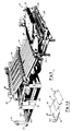
- Figure 1 is a perspective view of a downstacker assembly constructed in accordance with the present invention. For clarity, portions of the downstacker assembly are removed to disclose certain details thereof.
- Figure 1A is a profile schematic depicting relative locations of the major components of the downstacker assembly.
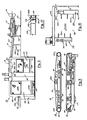
- Figure 2 is a side elevational view of the downstacker assembly of Figure 1. For clarity, the downstacker assembly is depicted in semi-detailed view in Figure 2.
- Figure 3 is a semi-detailed, partial cutaway, side elevational view of portions of the trim removal station.
- Figure 3A is a plan view of the upper web conveyor with the belts removed therefrom.
- Figure 3B is a plan view, in partial cutaway depiction, of the lower rope conveyor.
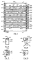
- Figure 4 is a top plan view of the feed station.
- Figure 5 is taken at 5 - 5 in Figure 4.
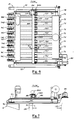
- Figure 6 is a top plan view of the vacuum conveyor station.
- Figure 7 is a semi-detailed, semi-schematic view in side elevation of the vacuum conveyor station.
- Figure 8 is a view taken at 8 - 8 in Figure 6.
- Figure 9 is a view taken at 9 - 9 in Figure 8.
- Figure 10 is a partially detailed depiction of the side rail support of the lateral support beam of the vacuum conveyor station.
- Figure 11 is a schematic representation depictiny the relative positions of the stationary backstop and the movable backstop of the downstacker station.
- Figures 12 and 12A are front elevational and top plan views, respectively, of the stationary backstop.
- Figure 12B is a side elevational, schematic representation of a portion of the stack staging assembly supported by the stationary backstop.
- Figure 12C is a partial cutaway view of the fork extension mechanism.
- Figure 12D is a partial detailed, side elevational view of a portion of the tamper assembly supported by the stationary backstop.
- Figure 13 is a side elevational, semi-detailed view of the movable backstop.
- Figure 14 is an enlarged view of a portion of the movable backstop shown in Figure 13.
- Figure 15 is a side elevational, semi-detailed view of one of the side tamper plates.
- Figure 16 is a side elevational view of a flexible curtain mechanism.
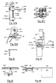
- Figure 17 is an enlarged detail of the dunnage clamp assembly disposed at the discharge opening of the downstacker station.
- Figure 18 is a schematic diagram of the control system for the downstacker assembly.
- Figure 1 shows in perspective view a downstacker assembly constructed in accordance with the present invention.
- Figure 1A is an outline of the major stations that comprise the downstacker assembly, and this outline is provided for convenience in locating the positions of the stations. More specifically:
- 12 is a trim removal station, and as shown, has its sandwich conveyor assembly partially open for maintenance access.
- 16 is a downstacker station.
- the 10 is a vacuum conveyor assembly portion of the down stacker station 16. As shown, the vacuum conveyor 18 is partially opened as when maintenance access is afforded.
- floor level elevation means the elevation of the concrete floor 20.
- Figure 2 is a side elevational depiction of these assemblies showing their positional relationship to the die cutter assembly 24 which directs cut blanks with trim to the trim removal station 12.
- the trim removal station 12 knocks the trim from the blanks and moves the blanks onto the upper surface of the feed station 14.
- the feed station 14 is an inclined vacuum conveyor which does two functions: it separates the laterally adjacent blanks are about 2-3 cm (an inch or so) apart as the blanks are moved up an incline to the lower run of the vacuum conveyor 18.
- the vacuum conveyor 18 moves the blanks to a position over a drop chute, and other mechanisms forcibly remove the blanks from the vacuum conveyor so that the blanks fall onto the progressively lowering platform conveyor disposed within the pit in the drop chute area.
- the paperboard blanks are substantially flat cardboard members having forward and rear portions with leading edges and rear edges, respectively.
- FIGS 3, 3A and 3B show various partial views of the trim removal station 12. Many details of the trim removal station 12 are conventional and will be omitted in the interest of brevity.
- 26 is a lower support frame and is also viewable in part in Figure 1.
- the web conveyor assembly 32 is an upper web conveyor assembly portion of the sandwich conveyor assembly 28.
- the web conveyor assembly 32 has an upper box frame 32A which is pivotably connected to the lower support frame 26 for pivoting of the web conveyor assembly 32 to an open position by pivoting support rams (viewable in part in Figure 1).
- a drive arbor 34A is powered by a sheave and belt (not shown) attached outboard to this arbor.
- a pair of arbors 34B are coaxially mounted so as to be adjustable to accommodate and matted conventionally to adjust to the stretch length of the belts. Also, an adjustable mid arbor 34C is provided.
- each of the beater members is comprised of the following.
- 40 is a central drive shaft driven by a sheave and power belt (not shown) attached outboard thereto;
- 46 and 48 are grooved arbors supported in spaced apart disposition via the frame 26, as shown in Figure 3B.
- 50 is a power drive assembly for the grooved arbor 48.
- adjustment arbors disposed beneath the top run of the rope members 52, each of which has a cam lift device 54A which elevates or lowers the adjustment arbor 54 upon turning of a set handle 54B.
- the endless belts 34 are preferably made of reinforced rubber or flexible plastic material having knob like protrusions in a pattern that generally makes multiple point contact against the top of the paperboard blanks and trim received from the cutter assembly 24.
- Figure 3 depicts the lower rope conveyor assembly 30 and the upper web conveyor assembly 32 in parallel, spaced apart disposition; this is for illustration only.
- the upper web conveyor assembly 32 is pivotally attached at one end to the support frame 26 and is pivotable to the open position shown in Figure 1 via appropriately disposed hydraulic rams. In the closed position, the lower runs of the web belts 34 are brought into close position to the upper runs of the rope members 52.
- the driven rotation of the central drive shafts 40 causes the beater members 36, 38 to beat against the web belts 34 as the beater bars 36, 38 rotate and strike the belts.
- the intensity of this vibratory motion on the paperboard blanks can be adjusted by the adjustment arbor 54 of the lower rope conveyor 30.
- the number and spacing of the rope members 52 on the grooved arbors 46, 48 are established to support the blanks while permitting trim removal to fall therebetween, with an appropriately positioned chute disposed therebeneath to eject collected trim to a disposition conveyor (not shown).
- the paperboard blanks less trim are directed via the trim removal station 12 to the feed station 14.
- the feed station 14 is a spacing conveyor which moves the paperboard blanks received from the trim removal station 12 to the downstacker station 16.
- the pit 22 is provided in order to lower the height of the downstacker station 16 for improved operator and maintenance accessibility.
- the feed station 14 is inclined to accommodate the difference in elevation between the die cutter assembly 24 and the vacuum conveyor station 18 of the downstacker station 16, and the pit 22 minimizes the incline.
- the feed station 14, as shown in Figure 2 spans the distance between the vacuum conveyer assembly 18 and the trim removal station 12, and comprises the following details of construction.
- 58 is a supporting framework.
- the conveyor 60 is a conveyor assembly supported by the supporting framework 58. As shown, one or more hydraulic rams 58A can be provided to lift or tilt the conveyor assembly 60 upwardly for underside accessibility.
- 62A through 62J are a plurality of conveyor belts.
- 64 depicts a plurality of sheaves supported at the lower end of the conveyor box frame 61 on a common drive shaft 64A which is supported by appropriately disposed journalled bearings along the end of the box frame 61.
- 64B depicts a drive belt assembly for rotating the sheaves 64 and thus the conveyor belts 62A - 62J together in the direction indicated by the flow arrow.
- 66A through 66J depicts a plurality of individually journalled sheaves at the upper end of the box frame 61, each such sheave supporting its individual conveyor belt 62.
- 68A through 68J depicts a plurality of vacuum chambers supported beneath the upper runs of the conveyor belt 62A through 62J, as shown.
- a belt support member 68D is attached to the upper end of the vaccum chamber 68A and has upwardly extending edges to confine the belt 62A in its continuous travel along the length of the vacuum chamber 68A.
- the belt support member 68D can be made of a wear resistent, polymeric material, if desired.
- a slot 68E is provided in the upper end of the vacuum chamber 68A and in the box support member 68D.
- a series of spaced apart apertures 68F are provided in the conveyor belt 62A which communicate via the slot 68E with the core 69 of the vacuum chamber 68A.
- a conventional vacuum system is provided, part of which is shown beneath the feed station 14 in Figure 1, to produce a vacuum in the core 69 and consequently at the apertures 68F in the conveyor belt 62A.
- the description for the conveyor belt 62A and its supporting structure also applies to the construction details of the remaining conveyor belts 62B through 62J and the supporting vacuum chambers 68B through 68J thereof.
- all of the conveyor belts 62A - 62J present an array of traveling vacuum apertures 68F.
- the blanks are moved up the incline of the conveyor assembly 60 and are fed to the vacuum conveyor station 18 as described further below.
- each of the sheaves 64 are commonly supported via the drive shaft 64A, while each of the sheaves 66A through 66J is individually supported on the opposing end of the box frame 61.
- the purpose of the latter arrangement is to permit some lateral adjustment to the conveyor belts 62A through 62J at the upper end of the box frame 61. That is, each of the sheaves 66A through 66J is supported (such as illustrated for sheaves 66A in Figure 4) via bolts 66K through slotted flanges which support the sheaves 66A for rotation.
- each of the sheaves 66A through 66J in a lateral direction so that the spacing between the conveyor belts 62A - 62J at the upper end of the box frame 61 can be selectively set to be greater at this end than at the lower end of the box frame 61.
- the conveyor belts 62A through 62J can be caused to diverge slightly in the direction of flow.
- the slack in the conveyor belts must be variable, so a conventional belt tension regulator (not shown) is provided which gives some slack during adjustment and then permits belt tightening.
- the upper ends of the underlying vacuum chambers 68A - 68J must be allowed lateral adjustment to track such lateral adjustment of the sheaves 66A - 66J, such as by a slideable lip support (not shown).
- the above described lateral adjustment is provided so that the paperboard blanks can be caused to separate slightly as such blanks are moved toward the upper end of the conveyor assembly 60.
- This small lateral separation given to the adjacent blanks is provided to prevent interference between adjacent blanks as these blanks are caused to fall into stacks in the downstacker assembly 16.
- the vacuum conveyor station 18 is comprised of a plurality of parallel conveyor belts which serve to move the paperboard blanks from the feed station 14 to over a drop chute in the downstacker station 16. As shown in Figure 6, the vacuum conveyor station 18 comprises the following structural details.
- rams 70A are provided to raise the vacuum conveyor station 18 to the position shown in Figure 1.
- 72 depicts a plurality of conveyor belts, with the individual belts being enumerated 72A through 72J.
- 74 and 76 depict plural sheaves supporting each of the conveyor belts 72, with 74A through 74J depicting the sheaves at one end and 76 depicting the sheaves at the other end of the frame 70.
- the sheaves 74A through 74J are individually supported with each being supported for slack adjustment of its respective conveyor belt.
- FIG. 82 depicts a plurality of vacuum chambers supported by the frame 70 beneath each of the conveyor belts 72A through 72J.
- One of the vacuum chambers is viewable in the semi-detailed view of Figure 7.
- Each of the vacuum chambers is constructed similarly to the vacuum chambers 68 of the conveyor assembly 60, and the conveyor belts 72A - 72J, which have a plurality of apertures similar to the above described conveyor belts 62, are caused to have vacuum suction in the same manner as the inclined conveyor of Figure 4, with the exception that the vacuum chambers 82 are inverted so that the vacuum is provided along the bottom runs of the conveyor belts 72A - 72J for the purpose discussed further below.
- the vacuum system used to create reduced pressure in the vacuum chambers 82 is conventional and need not be described.
- 84 is a blank impacting assembly which absorbs the momentum of the horizontally moving blanks and which separates the blanks from beneath the conveyor belts 72A through 72J.
- a portion of the blank impacting assembly 84 is depicted by 84A which is a blank striker assembly and which comprises the following construction details.
- 86 is a pair of rails supported along each side of the frame 70.
- the blank striker assembly 84A is to apply striking forces to the blanks carried beneath the conveyor belts 72A - 72J above the dropping chute 90 to separate the blacks frown the vacuum conveyor station 18.
- the blank impacting assembly 84 comprises a plurality of wheels which are disposed so as to be impacted by the forward edges of the paperboard blanks to cease the forward advancement of the blanks so that the blanks separated from the underside of the conveyor belts 72A - 72J, are caused to fall in the drop chute in a predetermined angular disposition and to stack uniformly in the downstacker station 16.
- the striker 92 depicts a plurality of strikers supported at intervals along the lateral support beam 88, one of the strikers 92 being shown in profile in Figure 8, a description of which will be common for all of such strikers 92.
- the striker 92 as shown in Figures 8 and 9, comprises the following structural details.
- 94 is a support frame and brace attached to the underside of the lateral support beam 88.
- 96 is a striker device supported at the lower end of the frame 94 and comprises a spring clutch mechanism.
- 98 depicts the clutch body portion of the striker device 96 which is mounted for rotation on the frame 94 and which has a locking gear 98B extensive therefrom.
- a spring mounted latch and solenoid mechanism which selectively engages the locking gear 98B.
- the clutch body portion 98 is a spring clutch of the type manufactured by Warner Electric Brake and Clutch Company of South Beloit, Illinois, and is preferably Model Number 275-1-0006, CB-2 series.
- a pulley portion 98A for rotating the striker device 96.
- the pulley portion 98A is caused to rotate, the latch engages the locking gear 98B which sets the striker arm 100 at a predetermined rest position.
- the pulley portion 98A however, is always free to rotate.
- the solenoid (not shown) is energized, the latch is lifted and the striker arm 100 can rotate with the pulley portion 98A.
- the striker arm 100 is spatially disposed beneath the lateral support beam 88 between a pair of adjacent conveyor belts 72 so as to be in position to strike a paperboard blank carried at the underside of the conveyor belts 72.
- a pulley belt 102C is driven by each of the pulleys 102B and drivingly engages the pulley 102B of each striker 92.
- the 104 is a power assembly provided to rotate the drive shaft 102 and thus to drive all of the pulleys 98B of the strikers 92 together. This provides for the striker arms 100 to react in unison as the solenoids of the clutches 98 are energized together, thereby providing multiple striking blows against the paperboard blanks across the underside of the vacuum conveyor station 18.
- each end of the lateral support beam 88 is supported by one of the rails 86, and a locking member 88A is provided so as to secure same thereto at a selected location along the rails 86.
- the purpose of this is to enable the positioning of the blank striker assembly 84A such that the strikers 92 are disposed just over the rear portions of the paperboard blanks regardless of the size of the blanks (that is, within the confines of the machine dimensions). This results in the strikers 92, driven in unison, being caused to strike the blanks at a predetermined position, and in a timed manner as described more fully below, to knock the rear portions of the blanks down and away from the underside of the vacuum conveyor belts 72.
- the downstacker station 16 is comprised of the following construction details.
- 112 is the stacking compartment which is open on the side shown and which has a slideable safety door 112A guarding access to the drop chute 90.
- 114 is the unstacking compartment which is open as shown and which has a slideable safety door 114A guarding access to entry thereof.
- 116 is a stacking assembly portion of the downstacker station 16 and is disposed in the drop chute 90 beneath the vacuum conveyor station 18 for receiving the falling blanks and for forming adjacently disposed stacks of paperboard blanks.
- the first elevator 118 is a first elevator or conveyor portion of the stacking assembly 116, and which is disposed within the stacking compartment 112.
- the first elevator 118 also sometimes herein referred to as a platform assembly, has a set of conventionally powered rollers 118A that are driven by a power source to rotate counter-clockwise (in Figure 2) to move paperboard blanks in the direction of the flow arrow.
- a chain and sprocket arrangement conventional in nature with counterweights, for selectively lifting and lowering the first elevator 118 within the stacking compartment 112.
- the rollers 118A serve as a platform surface for receiving blanks falling in the drop chute into stacks; as the stacks form, the first elevator 118 is progressively lowered by conventional power and control circuitry until a selected stack height is formed.
- the second elevator 120 is a stack retrieval assembly disposed within the unstacking compartment 114 and comprises a second elevator or conveyor 120A which, in similar manner to that of the first elevator 118, is supported by a conventional chain and sprocket arrangement (not shown) which is capable of selectively raising and lowering the second elevator 120A. In its lowered position, the second elevator 120A is aligned with the first elevator 118 (in its lowered position) to receive stacks of paperboard blanks therefrom.
- the second elevator 120A also has a set of conventionally powered rollers.
- the stack pusher assembly 122 is a stack pusher assembly (viewable in Figure 1) which is disposed to move the stacks received on the second elevator 120A in the direction of the flow arrow.
- the stack pusher assembly 122 has an arm which is positionable across the second elevator 120A once the stacks are received thereon, the arm being supported on each side of the second elevator 120A via traveler members which are driven via powered chain drives.
- the stack pusher assembly 122 is necessary to move stacks.
- the second elevator 120A In discharging the stacks of collected blanks from the stack retrieval assembly 120, the second elevator 120A is elevated to align with the receiving conveyor 124, at which time the stack pusher assembly 122 is activated to push the stacks onto the receiving conveyor 124 for removal via conventional means (not shown).
- dunnage clamp 126 is a dunnage clamp assembly which is supported by the frame 110 at the end of the receiving conveyor 124.
- This dunnage clamp 126 shown in partial detail in Figure 17, has a stationary frame member 126A which has an upstanding first gripping member 126B extending the width of the receiving conveyor 124.
- 128 is a second gripping member pivotally attached at its lower edge to the stationary frame member 126A.
- FIG. 130 is a conventional pancake type cylinder having an extendible member attached to the second gripping member 128 for selectively pivoting the second gripping member 128 to the open position depicted in Figure 17 and to a closed position in which the second gripping member 128 is pivoted to bear against the first gripping member 126B.
- the purpose of the dunnage clamp assembly 126 is to permit the placement and retention of dunnage under the stacks pushed from the second elevator 120A onto the receiving conveyor 124, the dunnage being necessary for the binding straps placed about the stacks during the colligation process.
- a piece of dunnage typically a flexible sheet of cardboard or the like
- the cylinder 130 is actuated to close the second gripping member 128 to securely grip the dunnage.
- the dunnage is then folded downwardly so as to overlay the end of the receiving conveyor 124.
- the cylinder 130 is actuated to open the second gripping member 128 to release the dunnage and to permit the stacks and dunnage to be moved along the receiving conveyor 124.
- a stationary backstop and a movable backstop disposed within the stacking compartment 112 is a stationary backstop and a movable backstop, the details of which will now be discussed.
- 136 is a laterally extending frame supported by the box frame 110.
- a power train (not shown) connected outboard to the support arbor 138 for bidirectional rotation thereof.
- cushion wheels 140 depicts a plurality of cushion wheels supported along the arbor 138 and which are disposed to be in the horizontal path of the paperboard blanks carried by the lower run of the vacuum conveyor assembly 18. That is, cushion wheels 140, having a semi-flexible striving surfaces, are disposed in the advancing path of the blanks so as to be struck by the leading edges of the blanks when the blanks are advanced over the drop chute 90. The rear portions of the blanks having just been struck downward blows by the strikers 92, the cushion wheels 140 impart a stopping force to the leading edges of the blanks, thusly effecting an angular disposition to the falling blanks, preferably with the rear edges of the blanks falling before the leading edges thereof.
- the arbor 138 supports and rotates the cushion wheels 140 in unison at a relatively low rotational speed just sufficient to present fresh impact surfaces regularly to the impacting blanks.
- the direction of rotation of the cushion wheel 140 is selected such that, upon impact by the blanks, the blanks will be caused to rebound with a proper force component. That is, it may be necessary to set the rotational direction differently, to modify the speed, or even stop the rotation for any particular paperboard blank as the characteristics of such blanks can vary greatly. In general, a downward vector at the leading edges of the blanks will be desired, as this assists in the dropping motion of the blanks. However, experience seems to indicate that other blank characteristics, such as pliancy of the leading edges, will also bear upon the rotational direction selection.
- the movable backstop 134 has a good many similarities to that discussed above for the stationary backstop 132, and more details of same will be provided herein-below. Meanwhile, with further discussion of the stationary backstop 132, it will be noted that this unit also serves to support portions of the stacking assembly 116; more specifically, the stationary backstop 132 supports part of a tamper assembly which serves to tamper the edges of the blanks as stacks of paperboard blanks are formed to provide substantially uniform sides to such stacks, and details of such tamper assembly are to be found in Figures 12 through 16.
- 144 depicts a powered cam mechanism which has several rotatable cams 144A that are connected to the tamper plate 142 via spring linkages as shown. Rotation of the cams 144A causes the tamper plate 142 to oscillate, and the disposition of the tamper plate 142 in front of the cushion wheels 140 causes the tamper plate 142 to tamper the leading edges of the blanks as such form stacks in the drop chute 90.
- the tamper plate 146 is a tamper plate shown in Figure 15 in partial detail.
- the tamper plate 146 is pivotably supported by a cantilever frame 146A which is slideably supported on a rail member 146B which, although not shown in Figure 12 and 12A, is mounted to the frame 136 and extends therealong above the cushion wheels 140.
- the frame 146A can be attached to a laterally extending screw member to move it to a position such that the tamper plate 146 is disposed adjacent to the outside edges of one of the outermost stacks formed on the first elevator 118.
- An oscillator cylinder 146C upon activation via a power source (not shown), oscillates the lower end of the tamper plate 146 to tamp the outside edges of the stacks being formed in the drop chute 90.
- Another tamper plate identical in construction to the tamper plate 146, is provided on the opposite side stacks to tamp the opposing edges of the stacks.
- the laterally extending screw member provided with two sections of oppositely pitched threads, can be rotated to move the tamper plates toward or away from each other to define the width of the dropping chute 90.
- the stacks will tend to form with gaps between adjacent stacks on the first elevator 118. While these gaps serve the useful feature of preventing side interference between falling blanks in the drop chute 90, it is desirable that the stacks be brought together once formed, as such gaps remaining between stacks, when banded on the receiving conveyor 124, will result in a certain amount of difficulty as the bundled stacks are transported. To prevent this ill effect, the present invention provides flexible curtains extending between adjacently disposed stacks to permit sufficient edge tampering to bring adjacent stacks into near touching, but not overlapping, disposition. One such curtain mechanism is shown in Figure 16, where the following numeral desigations are found.
- 148 is a flexible curtain mechanism which has a clamping support frame 148A.
- the support frame 148A depicts a slide rail frame variously extendible from the support frame 148A and which is set at a desired extension via set screws 148B in support loops 148C.
- the support frame 148A can be positionable along a lateral rail portion of the box frame 110 at a desired position, or if desired, the support frame of the curtain mechanism 148 can be configured to be supported by the rail member 146B (mentioned above for the tamper plates 146) and can cantilever out therefrom to permit proper placement.
- the stationary curtain 152 is caused to be withdraw from between the stacks.
- the number of such curtains 152, and the size thereof, will be determined by the number of stacks and the size of the paperboard blanks.
- the stacking assembly 116 also includes a stack staging assembly which is positionable beneath the vacuum conveyor station 18 for collecting falling blanks after a selected stack height has been achieved on the first elevator 118. That is, it is desirable that the flow of paperboard blanks be continuous and not interrupted during the time necessary to transfer the stacks from the first elevator 118 to the second elevator 120A. To this end, the following construction details of the stack staging assembly are provided, starting first with reference to Figures 12 and 12A.
- the first fork set 154A comprises the following construction details.
- 156 is a lateral beam member from which a plurality of fork members or tines 156A extend.
- a side profile is viewable in Figure 12B.
- the fork members 156A are slideably supported via a bearing block 156B supported at the ends thereof via guide posts (not shown) and via a plurality of screw members 156C which are in turn supported by the frame 136. As shown, the forks are extensive through slots in the front of the frame 136.
- FIG. 158 depicts a pair of rack gear members supported by the lateral beam member 156 and extensive parallel to the forks 156A.
- the partial cutaway view of Figure 12C shows a portion of one of these rack gear members in greater detail.
- each of the arbors 160 is one of a pair of a rotatable arbors bearingly supported by the bearing block 156B, and as shown in Figure 12C, each of the arbors 160 has a lower gear 160A is disposed to interact with one of the rack gears 158 extensive through the bearing block 156B.
- 160B depicts a top gear which is supported by each arbor 160 and which is disposed to interact with a rack gear 160C.
- the rack gear 160C will be more clearly viewable with reference in Figure 12A once again, where the rack gear 160C is partially viewable in a cutaway detail.
- 162 is a double acting cylinder which is supported by the bearing block 156B with a first end thereof, depicted as 162A, attached to a tab member 162B extensive from the bearing block 156B, and a second end 162C of the cylinder 162 connected to the rack gear 160C via a tab member 162D extensive therefrom.
- the rack gear 160C is caused to slide laterally relative to the bearing block 156B.
- the rack gear 160C is slideably retained on the bearing block 156B via a support member 156D in conventional manner.
- the rack gear 160C is moved thereby, interacting with the gears 160B to rotate the arbors 160.
- This causes the rotation of the gears 160A, which causes the rack gears 158 to move relative to the bearing block 156B.
- the rack gears 158 are attached to the lateral beam member 156, this causes the beam 156 to move toward or away from the nearing block 156B, thereby causing the forks 156A to move between the retracted and extended positions relative to the frame 136. More about this in the discussion of the second fork set supported in similar fashion on the movable backstop 134 will clarify the function of these fork sets.
- FIG. 13 therein is depicted a side elevational view of the movable backstop 134 in which the components thereof are enumerated as follows.
- 164 is a laterally extending frame slidingly supported at each end via a pair of support rails (not shown) which are in turn supported by the box frame 110. Also, a pair of screw rails 164A are provided to selectively move and position the frame 164. The rails 164A also appear in Figures 12 and 12A where a drive train 164B is shown for the simultaneous rotation of the rails 164A to move the movable backstop 134 to a desired position along the rails 164A via interaction therewith by appropriately disposed gears (not shown) in the frame 164.
- the second fork set 154B depicts a portion of a power train which drive: a laterally disposed arbor (not shown) to effect the raising and lowering of the second fork set 154B.
- the structural details of the second fork set 154B are identical to that provided above for the first fork set 154A and need not be provided herein as such is not deemed necessary. Instead, live numerals will indicate the same component members of the second fork set 154B.
- the second fork set 154B also comprises a laterally extending beam member 156 and a plurality of fork members 156A that are extendible and retractable relative to the frame 164 via a bearing block 156B supported and positionable via appropriately disposed, but not shown, screw members 156C.
- a cylinder 162 is also provided, together with its rack gear 160C, supported appropriately to actuate the components discussed above with reference to Figure 12C for the movable backstop 134, the result being the selective extension and retraction of the second fork set 154B.
- the first and second fork sets 154A and 154B are extendible toward each other and intermesh somewhat to form a temporary cradle beneath the vacuum conveyor station 18 to receive falling paperboard blanks to permit removing of stacks of the blanks on the first elevator 118 without stopping the flow of such blanks. Further, as the extended first and second fork sets 154A, 154B collect filling blanks in the temporary cradle provided thereby, the first and second fork sets 154A, 154B are progressively lowered via the supporting screw members 156C.
- the first elevator 118 is again raised to just below the forks of the first and second fork sets 154A, 154B, and the forks 156A thereof are simultaneously retracted in order to transfer the collected blanks to the upper platform surface of the first elevator 118.
- the positioning of the movable backstop 134 is determined along the supporting rails 164A to define the length of the drop chute 90 to accommodate the size of paperboard blanks being downstacked from the die cutter assembly 24.
- the movable backstop 134 is positioned so as to serve as a back boundary at the rear edges of the blanks carried over the drop chute 90 via the vacuum conveyor station 18.
- 168 depicts a panel member supported by the frame 164 which serves as the back boundary of the falling blanks in the drop chute 90.
- a portion of the panel member 168 is shown in enlarged view in Figure 14 where 168A depicts an overhanging lip portion thereof.
- the purpose of the lip portion 168A is to permit clearance to the falling blanks in the drop chute 90, but also, to prevent upward flight of the rear edges of the blanks as the blanks rebound from impact with the cushion wheels 140 of the stationary backstop 132. This feature has proven helpful to prevent the trailing edges of the blanks from going upward into the advancing path of following blanks, and it is believed to be useful in the avoidance of some potential jams.
- control system 170 in the schematic diagram of Figure 18 represents a control system which ties together the operations of the various stations and assures a continuous operation of the progressive steps in the work performed by the downstacker assembly 10.
- the control system 170 first controls the flow of paperboard blanks from the die cutter assembly 24.
- the die cutter assembly 24 does not form a part of the present invention, as the downstacker assembly 10 may find usefulness in other unit operations involving blanks and the like. Nevertheless, the control system 170 is tied in a control sense to the die cutter assembly 24 in order to command responses from the several work stations of the downstacker assembly 10 in a coordinated manner appropriate to the blanks provided by the die cutter assembly 24.
- a group of data collection and storage locations are synchronized by timing signals generated at motor locations at the various work stations.
- This data is sent to, and accumulated by, the shift register stations and the central control system 170.
- the number of blanks and location of same are tracked, beginning with the die cutter assembly 24, as shown in Figure 18, to include the trim removal station 12, the feed station 14, the downstacker station 16 (including the vacuum conveyor station 18), and the stack retrieval assembly 120.
- the fork members 156A are caused to be positioned beneath the vacuum conveyor station 18 to form a temporary cradle to catch the falling blanks during the time interval of stack removal from the first elevator 118. While it is possible to move the forks 156A into cradle position during the time in which blanks are falling in the drop chute 90, the probability of causing blank interference by such fork insertion increases as the rate of blank flow is increased. It has been determined that blank jams of this type can be eliminated by providing a gap of about a three second duration in the flow of blanks.
- control system 170 signalling a time delay to the die cutter assembly 24, after which time the die cutter assembly 24 again is caused to feed blanks to the trim removal station 12.
- This gap in the flow of paperboard blanks can be electrically tracked so that the arrival of the gap at the drop chute 90 is known, and the forks 156A of the stack staging assembly can be extended across the drop chute 90 during the gap time without interference with the falling blanks.
- control system 170 Other features of the control system 170, such as the operations of starting and stopping, jogging and speed controlling of the downstacker assembly 10, will be commonly known and need not be described herein. It will be appreciated then that the control system 170 will be a useful feature of the downstacker assembly 10.
Landscapes
- Engineering & Computer Science (AREA)
- Mechanical Engineering (AREA)
- Making Paper Articles (AREA)
- Laminated Bodies (AREA)
- Flexible Shafts (AREA)
- Portable Nailing Machines And Staplers (AREA)
Claims (15)
Priority Applications (1)
| Application Number | Priority Date | Filing Date | Title |
|---|---|---|---|
| AT87906544T ATE72419T1 (de) | 1986-09-19 | 1987-09-18 | Stapler. |
Applications Claiming Priority (2)
| Application Number | Priority Date | Filing Date | Title |
|---|---|---|---|
| US06/909,557 US4740193A (en) | 1986-09-19 | 1986-09-19 | Downstacker assembly |
| US909557 | 1986-09-19 |
Publications (3)
| Publication Number | Publication Date |
|---|---|
| EP0282574A1 EP0282574A1 (de) | 1988-09-21 |
| EP0282574A4 EP0282574A4 (de) | 1989-02-07 |
| EP0282574B1 true EP0282574B1 (de) | 1992-02-05 |
Family
ID=25427450
Family Applications (1)
| Application Number | Title | Priority Date | Filing Date |
|---|---|---|---|
| EP87906544A Expired - Lifetime EP0282574B1 (de) | 1986-09-19 | 1987-09-18 | Stapler |
Country Status (7)
| Country | Link |
|---|---|
| US (2) | US4740193A (de) |
| EP (1) | EP0282574B1 (de) |
| AT (1) | ATE72419T1 (de) |
| AU (1) | AU602173B2 (de) |
| CA (1) | CA1302447C (de) |
| DE (1) | DE3776647D1 (de) |
| WO (1) | WO1988001908A1 (de) |
Families Citing this family (24)
| Publication number | Priority date | Publication date | Assignee | Title |
|---|---|---|---|---|
| FR2611586A1 (fr) * | 1987-02-24 | 1988-09-09 | Dupuy Eng Sa | Dispositif pour l'assemblage de decoupes notamment en vue de la realisation d'emballages |
| US5026249A (en) * | 1989-05-26 | 1991-06-25 | Thermoguard Equipment, Inc. | Apparatus for stacking corrugated sheet material |
| DE4013302A1 (de) * | 1990-04-26 | 1991-10-31 | Koenig & Bauer Ag | Vorrichtung zum foerdern eines insbesondere geschuppten stroms von bogen |
| US5150168A (en) * | 1991-08-01 | 1992-09-22 | Xerox Corporation | Duplex printer and method of printing |
| US5656005A (en) * | 1995-04-24 | 1997-08-12 | Marquip, Inc. | Method and apparatus for automatically forming corrugated sheets into block-shaped units of optimal size |
| CA2259785C (en) | 1999-01-19 | 2008-07-29 | Peter E. Sandford | Jogger member, system and method for mounting jogger members and female and male blanking dies provided therewith |
| US6688083B1 (en) * | 2000-11-17 | 2004-02-10 | Lockheed Martin Corporation | Drop control mechanism for flat articles |
| DE10300233B3 (de) * | 2003-01-08 | 2004-05-27 | WINKLER + DüNNEBIER AG | Vorrichtung und Verfahren zur Ablage von aus einer Materialbahn ausgeschnittenen Flachmaterialstücken |
| TWI241241B (en) * | 2003-10-13 | 2005-10-11 | Bobst Sa | Blank diecutting machine |
| JP2005200133A (ja) * | 2004-01-14 | 2005-07-28 | Oki Data Corp | 画像形成装置 |
| US20060249894A1 (en) * | 2005-04-22 | 2006-11-09 | Halm Industries Co., Inc. | Adjustable aligner mechanism |
| US7416073B1 (en) * | 2007-02-09 | 2008-08-26 | Geo. M. Martin Company | Diverting flat belt support system |
| US8505908B2 (en) | 2010-04-13 | 2013-08-13 | J&L Group International, Llc | Sheet deceleration apparatus and method |
| US9027737B2 (en) | 2011-03-04 | 2015-05-12 | Geo. M. Martin Company | Scrubber layboy |
| EP2739553B1 (de) * | 2011-08-04 | 2018-03-28 | Alliance Machine Systems International, LLC | Vorrichtung und verfahren zum stapeln von wellblechmaterial |
| US10967534B2 (en) | 2012-06-04 | 2021-04-06 | Geo. M. Martin Company | Scrap scraper |
| KR101779277B1 (ko) * | 2013-03-18 | 2017-09-18 | 봅스트 맥스 에스에이 | 이송 동안 플랫 물체를 배출하기 위한 디바이스 |
| US9181062B2 (en) * | 2013-07-30 | 2015-11-10 | Alliance Machine Systems International, Llc | Trim arm adjustment assembly automated setting |
| US9828185B1 (en) | 2016-10-04 | 2017-11-28 | Geo. M. Martin Company | Fixed discharge variable length stacker |
| US10086526B2 (en) | 2016-10-04 | 2018-10-02 | Geo. M. Martin Company | Puffer pan |
| US10414613B2 (en) | 2016-10-07 | 2019-09-17 | Geo. M. Martin Company | Stacker load change cycle |
| DE102019102775A1 (de) * | 2019-02-05 | 2020-08-06 | Koenig & Bauer Ag | Bogenbearbeitungsmaschine mit Formgebungseinrichtung und oberem Saugtransportmittel |
| CN110482302A (zh) * | 2019-08-10 | 2019-11-22 | 天津市鑫源包装有限公司 | 自动叠料设备和生产方法 |
| US20220356031A1 (en) * | 2021-05-04 | 2022-11-10 | A. G. Stacker Inc. | Front end conveyor having blower for dislodging scrap |
Family Cites Families (23)
| Publication number | Priority date | Publication date | Assignee | Title |
|---|---|---|---|---|
| US2205767A (en) * | 1938-07-05 | 1940-06-25 | George E Lamb | Continuous layboy |
| US2895552A (en) * | 1955-08-10 | 1959-07-21 | John Waldron Corp | Transverse web cutting apparatus having sheet delivery mechanism using timed vacuum belts |
| US3022999A (en) * | 1959-05-25 | 1962-02-27 | Lamb Grays Harbor Co Inc | Spring loaded pivoted forward stop for paper stacking mechanism |
| US3263827A (en) * | 1963-09-20 | 1966-08-02 | Fmc Corp | Article handling apparatus |
| US3307326A (en) * | 1964-04-21 | 1967-03-07 | Sunds Verkst Er Aktiebolag | Corrugated board bundler |
| US3270929A (en) * | 1964-08-13 | 1966-09-06 | Jr Joseph E Foster | Vibration die cut stripping machine |
| US3362707A (en) * | 1964-11-27 | 1968-01-09 | Ahlstroem Oy | Auxiliary stack holder |
| US3477711A (en) * | 1967-04-25 | 1969-11-11 | Cameron Machine Co | Apparatus and method for handling long sheets |
| US3463485A (en) * | 1968-10-02 | 1969-08-26 | Southworth Machine Co | Method of ream collecting single sheets |
| DE2062370A1 (de) * | 1970-12-18 | 1972-06-22 | Hans Jenz Maschinen U Fahrzeug | Vorrichtung zum Ablegen von blattförmigen Werkstücken |
| US3698708A (en) * | 1971-01-18 | 1972-10-17 | Carothers Sheet Metal Co | Veneer stacker |
| US3765993A (en) * | 1971-02-22 | 1973-10-16 | Ramar Mfg Co Of Florida Inc | A layup machine for assembling panels having a pair of skins and a core |
| US3820779A (en) * | 1972-04-24 | 1974-06-28 | Deritend Eng Co | Sheet delivery apparatus |
| US3892168A (en) * | 1974-01-14 | 1975-07-01 | Molins Machine Co Inc | Counter ejector |
| GB1505185A (en) * | 1975-04-30 | 1978-03-30 | Deritend Eng Co | Sheet handling apparatus |
| AU496775B2 (en) * | 1975-07-22 | 1978-10-26 | Hans Lingl | Rearranging rows of articles |
| US4130207A (en) * | 1976-03-05 | 1978-12-19 | The Wessel Company, Inc. | Apparatus for stacking booklets from the top |
| US4295842A (en) * | 1979-12-31 | 1981-10-20 | The Ward Machinery Company | Stripping device for removing waste sheet board |
| US4324522A (en) * | 1980-03-04 | 1982-04-13 | Bucciconi Engineering Co., Inc. | Metal sheet handling machine |
| US4494745A (en) * | 1981-12-16 | 1985-01-22 | The Ward Machinery Company | Feeding apparatus for paperboard sheets |
| US4474565A (en) * | 1982-02-25 | 1984-10-02 | The Ward Machinery Company | Blank stripping apparatus for rotary die cutters |
| US4500244A (en) * | 1982-12-20 | 1985-02-19 | The Ward Machinery Company | Air lift for blank stackers |
| US4500243A (en) * | 1983-03-07 | 1985-02-19 | The Ward Machinery Company | Blank stacking apparatus |
-
1986
- 1986-09-19 US US06/909,557 patent/US4740193A/en not_active Expired - Lifetime
-
1987
- 1987-09-18 AU AU80212/87A patent/AU602173B2/en not_active Ceased
- 1987-09-18 CA CA000547305A patent/CA1302447C/en not_active Expired - Lifetime
- 1987-09-18 AT AT87906544T patent/ATE72419T1/de not_active IP Right Cessation
- 1987-09-18 WO PCT/US1987/002410 patent/WO1988001908A1/en not_active Ceased
- 1987-09-18 DE DE8787906544T patent/DE3776647D1/de not_active Expired - Fee Related
- 1987-09-18 EP EP87906544A patent/EP0282574B1/de not_active Expired - Lifetime
-
1988
- 1988-04-25 US US07/185,760 patent/US4900297A/en not_active Expired - Lifetime
Also Published As
| Publication number | Publication date |
|---|---|
| ATE72419T1 (de) | 1992-02-15 |
| CA1302447C (en) | 1992-06-02 |
| EP0282574A4 (de) | 1989-02-07 |
| EP0282574A1 (de) | 1988-09-21 |
| AU602173B2 (en) | 1990-10-04 |
| DE3776647D1 (en) | 1992-03-19 |
| US4740193A (en) | 1988-04-26 |
| WO1988001908A1 (en) | 1988-03-24 |
| US4900297A (en) | 1990-02-13 |
| AU8021287A (en) | 1988-04-07 |
Similar Documents
| Publication | Publication Date | Title |
|---|---|---|
| EP0282574B1 (de) | Stapler | |
| US4162649A (en) | Sheet stack divider | |
| EP0187344B1 (de) | Verfahren und Vorrichtung zum Herstellen einzelner, aus einer zickzackförmig gefalteten Materialbahn bestehender Stapel | |
| US4436472A (en) | Sheet piling devices | |
| US5026249A (en) | Apparatus for stacking corrugated sheet material | |
| EP0205064B1 (de) | Anlage zum automatischen Stapeln und Ausrichten von Plattenstapeln unterschiedlicher Grösse | |
| US4984963A (en) | Stacking bundles of flat-folded boxes of corrugated board | |
| US4508333A (en) | Sheet stacking apparatus | |
| US5423657A (en) | Prefeeder for stacked sheets of paperboard products | |
| US5628505A (en) | Apparatus for stacking continuously arriving sheets | |
| US6672582B2 (en) | Delivery and ejection device for flat elements into a machine working them | |
| CA1206492A (en) | Machine for stacking automatically pack of panels of different sizes on respective lifting platforms | |
| JPH06100166A (ja) | 枚葉紙、本等のパックのパレット載置方法 | |
| US3960374A (en) | Sheet delivery system | |
| EP0792831A1 (de) | Vorrichtung zum Sammeln und Stapeln von Schichtwerkstoffen, und ein Stapelverfahren | |
| JPH09169465A (ja) | 印刷機の排紙装置におけるノンストップパイル交換装置 | |
| KR20050028792A (ko) | 스택커 번들러 및 그 제어방법 | |
| JP2000509695A (ja) | 積み紙交換装置 | |
| US5511935A (en) | Paper stack conveyor | |
| US3762579A (en) | Apparatus for setting down and stacking products, more particularly pantiles | |
| US4136864A (en) | Sheet stacking device | |
| CA1146510A (en) | Continuous on machine ream cartoning | |
| US3727495A (en) | Automatic partition cutting machine | |
| US3978785A (en) | Stacking and bundling machine | |
| US4784559A (en) | Apparatus for subdividing piles of superimposed stacks of paper sheets and the like |
Legal Events
| Date | Code | Title | Description |
|---|---|---|---|
| PUAI | Public reference made under article 153(3) epc to a published international application that has entered the european phase |
Free format text: ORIGINAL CODE: 0009012 |
|
| AK | Designated contracting states |
Kind code of ref document: A1 Designated state(s): AT BE CH DE FR GB IT LI LU NL SE |
|
| 17P | Request for examination filed |
Effective date: 19880830 |
|
| A4 | Supplementary search report drawn up and despatched |
Effective date: 19890207 |
|
| 17Q | First examination report despatched |
Effective date: 19901029 |
|
| GRAA | (expected) grant |
Free format text: ORIGINAL CODE: 0009210 |
|
| AK | Designated contracting states |
Kind code of ref document: B1 Designated state(s): AT BE CH DE FR GB IT LI LU NL SE |
|
| PG25 | Lapsed in a contracting state [announced via postgrant information from national office to epo] |
Ref country code: IT Free format text: LAPSE BECAUSE OF FAILURE TO SUBMIT A TRANSLATION OF THE DESCRIPTION OR TO PAY THE FEE WITHIN THE PRE;WARNING: LAPSES OF ITALIAN PATENTS WITH EFFECTIVE DATE BEFORE 2007 MAY HAVE OCCURRED AT ANY TIME BEFORE 2007. THE CORRECT EFFECTIVE DATE MAY BE DIFFERENT FROM THE ONE RECORDED.SCRIBED TIME-LIMIT Effective date: 19920205 Ref country code: SE Effective date: 19920205 Ref country code: NL Effective date: 19920205 Ref country code: CH Effective date: 19920205 Ref country code: LI Effective date: 19920205 Ref country code: BE Effective date: 19920205 Ref country code: FR Effective date: 19920205 Ref country code: AT Effective date: 19920205 |
|
| REF | Corresponds to: |
Ref document number: 72419 Country of ref document: AT Date of ref document: 19920215 Kind code of ref document: T |
|
| REF | Corresponds to: |
Ref document number: 3776647 Country of ref document: DE Date of ref document: 19920319 |
|
| REG | Reference to a national code |
Ref country code: CH Ref legal event code: PL |
|
| EN | Fr: translation not filed | ||
| NLV1 | Nl: lapsed or annulled due to failure to fulfill the requirements of art. 29p and 29m of the patents act | ||
| PG25 | Lapsed in a contracting state [announced via postgrant information from national office to epo] |
Ref country code: LU Free format text: LAPSE BECAUSE OF NON-PAYMENT OF DUE FEES Effective date: 19920930 |
|
| PLBE | No opposition filed within time limit |
Free format text: ORIGINAL CODE: 0009261 |
|
| STAA | Information on the status of an ep patent application or granted ep patent |
Free format text: STATUS: NO OPPOSITION FILED WITHIN TIME LIMIT |
|
| 26N | No opposition filed | ||
| PG25 | Lapsed in a contracting state [announced via postgrant information from national office to epo] |
Ref country code: DE Effective date: 19930602 |
|
| PGFP | Annual fee paid to national office [announced via postgrant information from national office to epo] |
Ref country code: GB Payment date: 19980911 Year of fee payment: 12 |
|
| PG25 | Lapsed in a contracting state [announced via postgrant information from national office to epo] |
Ref country code: GB Free format text: LAPSE BECAUSE OF NON-PAYMENT OF DUE FEES Effective date: 19990918 |
|
| GBPC | Gb: european patent ceased through non-payment of renewal fee |
Effective date: 19990918 |