EP0280803A2 - Wasserwiderstands-Lastsystem - Google Patents
Wasserwiderstands-Lastsystem Download PDFInfo
- Publication number
- EP0280803A2 EP0280803A2 EP87304416A EP87304416A EP0280803A2 EP 0280803 A2 EP0280803 A2 EP 0280803A2 EP 87304416 A EP87304416 A EP 87304416A EP 87304416 A EP87304416 A EP 87304416A EP 0280803 A2 EP0280803 A2 EP 0280803A2
- Authority
- EP
- European Patent Office
- Prior art keywords
- water
- electrode
- load system
- resistance load
- water resistance
- Prior art date
- Legal status (The legal status is an assumption and is not a legal conclusion. Google has not performed a legal analysis and makes no representation as to the accuracy of the status listed.)
- Granted
Links
Images


Classifications
-
- H—ELECTRICITY
- H01—ELECTRIC ELEMENTS
- H01C—RESISTORS
- H01C1/00—Details
- H01C1/08—Cooling, heating or ventilating arrangements
- H01C1/082—Cooling, heating or ventilating arrangements using forced fluid flow
-
- H—ELECTRICITY
- H01—ELECTRIC ELEMENTS
- H01C—RESISTORS
- H01C10/00—Adjustable resistors
- H01C10/02—Liquid resistors
Definitions
- This invention relates to a water resistance load system used for measurement or testing of output characteristics of generators and various other electric power source devices including inverters.
- Fig. 1 shows a water resistor ⁇ . It comprises three electrode plates (or electrode cylinders) b, to which three-phase high pressure cables a are connected.
- the electrode plates b are suspended from a support d provided on a water trough c about 3 m in each side and 2 m in height.
- the extent of immersion of the electrode plates in water is controlled to control the load, and the output power of the power source device is consumed with water in the water trough c as resistor.
- water temperature is gradually increased to increase the electric conductivity of water. This means that dielectric breakdown of water will eventually occur to generate a dangerous electric arc.
- the water resistor ⁇ requires when using it the water trough c, support for suspending it and pump and piping for supplying water from the water storage pool.
- the overall equipment therefore, is rather elaborate, requiring a great deal of labor for its transportation and assembly.
- a further grave disadvantage of the water resistor ⁇ is that the use thereof leads to the production of a great quantity of warm drain water.
- the water resistor as load system used for the measurement of characteristics of a power source device has the problems that generation of an electric arc is possible when it is used under a high voltage condition, that a large quantity of water is required, that elaborate equipment and labor are required, that the resistance provided is instable and that a great quantity of warm water is drained.
- the input power to the electrode section varies due to various causes. Although it may be held constant with suitable means by monitoring it at all time, from the standpoint of energy saving a device for automatically holding the input constant is necessary.
- An object of the invention is to provide a water resistance load system, which is less subject to electric arc generation although water is used, does not produce warm drain water, permits extreme reduction of the quantity of water used and permits a stable resistance to be obtained.
- Another object of the invention is to provide a water resistance load system provided with a water resistor, which requires less labor for its transporta tion and installation, permits a stable resistance to be obtained and has excellent stability.
- a further object of the invention is to provide a water resistance load system provided with an electrode water cooling unit, which permits recycle use without production of warm drain water and permits extreme reduction of the quantity of cooling water.
- a still further object of the invention is to provide a water resistance load system provided with a water resistor having an insulation sheath with electric arc protective means effective for solving the problem of the electric arc burning accident of the insulation sheath.
- a further yet object of the invention is to provide a water resistance load system provided with a water resistor with electric arc discharge prevention means effective for solving the problem of electric arc burning accident of the insulation sheath.
- a yet another object of the invention is to provide a water resistance load system provided with an automatic insulation sheath operation controlling unit for maintaining the input power to be constant by raising or lowering the insulation sheath automatically in accordance with variations of the input power to an electrode section of the water resistor.
- a further object of the invention is to provide a water resistance load system provided with an electrode water temperature controlling unit effective for maintaining the temperature of electrode water to be constant through automatic control of the capacity of an electrode water cooling unit, thereby stabilizing the resistance of electrode water used as resistor.
- a water resistance load system which comprises a water resistor including a cylindrical base electrode with a bottom for storing a predetermined amount of circulatedly supplied water, a cylindrical main electrode penetrating an insulating support mounted in the center of the bottom of the base electrode and extending into the base electrode, a power cable of a power source device being connected to a projecting lower end of the main electrode and an insulation sheath suspended for vertical movement and covering the main electrode for controlling the exposed length of the main electrode, and an electrode water cooling unit including a radiator, warm water drained from the water resistor being introduced into and passed through the radiator before being supplied to the water resistor, a spray tube for spraying water against the radiator to cool warm water in the radiator with the latent heat of evaporation of the sprayed water, and a fan and an air guide for air cooling the surface of the radiator guiding generated steam to a space.
- the system A comprises a water resistor B.
- the water resistor B includes a cylindrical base electrode 22 having a bottom with a drain hole 20 for storing a predetermined quantity of water, a cylindrical main electrode 28 penetrating an insulator or like insulating support 24 secured to the center of the bottom of the base electrode 32 and extending into the base electrode 32, a power cable 26 of a power source device being connected to the lower end of the insulating support 24, and an insulation sheath 30 suspended for vertical movement to cover part of the main electrode 28 for controlling the exposed length thereof.
- main electrode 28 in the water resistor B is shown in Figs. 2 to 5, actually two or more, e.g., three in the case of Fig. 6, main electrodes are provided on a base S.
- the three main electrodes 28 are connected to respective three phases of the power source device, while they are inter-connected and grounded. Thus, a Y-connection resistor is formed.
- the system shown in Figs. 2 to 5 is a high-voltage low-current system.
- a low-voltage high-current system is different from this system in that the main electrode 28 has a greater diameter and defines a smaller gap with the base electrode 22.
- Fig. 7 shows an example of the construction of the water resistor B.
- the insulation sheath 30 is made of a plastic material, e.g., polypropyrene or polyethylene tetrafluoride, having heat insulation of 100°C or above, and its ceiling 30a is provided with a water supply port 32.
- a fine ceramic ring 34 is fitted, which has electric arc heat resistance.
- the fine ceramic ring 34 has the same outer diameter as the inner diameter of the insulation sheath 30, and it is provided at the lower end with a flange-like outer projection having the same thickness as the thickness of the lower end of the insulation sheath 30.
- the water supply port 32 is provided in the ceiling 30a.
- Fig. 8 shows a different example of the construction of the water resistor B ⁇ .
- the insulation sheath 30 is again made of a plastic material, e.g., polypropyrene or "Teflon" (a tade name by Dupon Inc.), having heat insulation of 100°C or above.
- a fine ceramic ring 34 having electric arc heat resistance.
- the insulating support 24 is provided with a plurality of water supply ports 36 such as to surround the main electrode 28. It is possible to provide only a single water supply port.
- Fig. 9 shows an example of the insulation sheath 30.
- a fine ceramic ring 38 having electric arc heat resistance is fitted as electric arc protective means on the outer periphery of the lower end of the insulation sheath 30.
- Fig. 10 shows another example of the insulation sheath 30.
- a metallic electric arc ring 40 is fitted as electric arc protective means on the outer periphery of the lower end of the insulation sheath 30, and also the insulation sheath 30 is formed in its portion in contact with the inner periphery of the electric arc ring 40 with a plurality of circumferentially uniformly spaced-apart see-through holes 42.
- Slide contacts 44 extend through the respective see-through holes 42 and extend obliquely outwardly toward the center of the insulation sheath 30. Their bent portions are in contact with the outer periphery of the main electrode 28.
- Fig. 11 shows a further example of the insulation sheath 30.
- a metallic arc ring 46 is fitted as electric arc protective means in the inner periphery of the lower end of the insulation sheath 30, and also the insulation sheath 30 is formed in its portion in contact with the outer periphery of the electric arc ring 46 with a plurality of circumferentially uniformly spaced-apart see-through holes 48.
- Slide contacts 50 extend through the respective see-through holes 48 and extend obliquely outwardly. Their bend portions are in contact with the outer periphery of the base electrode 22.
- the system shown comprises an automatic insulation sheath operation controlling unit 52 for the water resistor.
- the unit 51 includes a measuring instrument 56 serving as a power meter or an ammeter provided between grounded cable 54 and power cable 26 for measuring power or current supplied to the cable and producing a measurement signal S1, which is either a power measurement signal or a current measurement signal, a controller 58 having a comparator for receiving the measurement signal S1 and producing a comparison value control signal S2 representing a difference or a radio of the received signal S1 with respect to a stored reference value of power or current, and an insulation sheath driver 60 for commanding upward or downward driving of the suspended insulation sheath 30 in response to the comparison value control signal S1.
- a measuring instrument 56 serving as a power meter or an ammeter provided between grounded cable 54 and power cable 26 for measuring power or current supplied to the cable and producing a measurement signal S1, which is either a power measurement signal or a current measurement signal
- a controller 58 having a comparator for receiving the measurement signal S1 and producing a
- the controlling unit 52 may be an analog system or a digital system or a combination of analog and digital systems.
- an analog/digital converter is of course inserted at a suitable intermediate position.
- Fig. 12 shows an example of the automatic insulation sheath operation controlling unit.
- This operating unit 60 ⁇ includes a drive motor 62 (e.g., a stepping motor, a pulse motor, etc.) to be operated for a rotational angle proportional to the difference or ratio of the comparison value control signal S2 provided from the controller 58 and a drum 68 for taking up an insulating string 66 consisting of a synthetic resin rope or a cloth rope, which is coupled to a motor shaft 64 of the drive motor 62 and suspends the insulation sheath 30.
- a drive motor 62 e.g., a stepping motor, a pulse motor, etc.
- Fig. 13 shows a different example of the automatic insulation sheath operation controlling unit.
- This unit 60 ⁇ includes a drive motor 70 to be rotated by a rotational angle proportional to the difference or ratio of the comparison value control signal S2, a pinion 74 secured to an end of a motor shaft 72 of the drive motor 70 and a rack 78 in mesh with a pinion 74 formed on one side of a hanging bar 76 hanging at the lower end the insulation sheath 30.
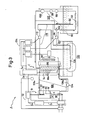
- the system shown in Fig. 2 further comprises an electrode water cooling unit C according to the invention.
- This unit C serves to cool the warm water drained from the water resistor B and supply the cooled water back to the water resistor B.
- It includes a radiator 80, a spray tube 82 for spraying water to the back side of the radiator 80, a fan for supplying cooling air from the back side of the sprays, an air guide 86 for guiding air forced out by the fan 84 through the radiator 80 to the front side thereof to the space above, a water recovery tank 88 disposed beneath the radiator 80 for recovering water having been sprayed to the radiator 80 from the spray tube 82 and falling therefrom, and an electrode water storage tank 90 for storing electrode water W to be circulated through the radiator 80.
- the various components noted above are interconnected by the following ductlines.
- a purified water supply ductline 102 in which water stored in a water storage tank 90 is pumped through a water supply pipe 92 vertically immersed in the stored water by a pump 94 and passed through filters 96 and 98 and a purifier 100 for increasing the purity of water.
- a cooling water circulation ductline 106 in which water supplied from the purified water supply ductline 102 to its inlet side is supplied to the water resistor B, and warm water drained from the water resistor B is supplied by a pump 104 to a lower water inlet 80a of the radiator 80.
- a flushing/return ductline 110 in which electrode water W branched from the outlet side 106b of the cooling water circulation ductline 106 upstream the water inlet 80a of the radiator 80 is pumped out by the pump 94 to be supplied to a cooling coil 108 for cooling and is then returned to the purified water supply ductline 102.
- a spray water supply ductline 116 in which water is pumped out by a spray water pump 112 through either the water supply pipe 92 vertically immersed in the water storage tank 90 or a pipe 114 vertically immersed in the water recovery tank 88 and is supplied to the spray tube 82.
- These ductlines are interconnected through directional control valves 118, 120 and 122.
- Reference numeral 124 in Fig. 2 designates a fan motor, 126, 128 and 130 speed controllers with inverter for the fan motor 124, pump 94 and spray water pump 112, and 132 a cooling coil.
- All the above equipment including the water resistor B may be mounted on a truck or the like so that it can be transported speedily. Further, the storage tank 90 may be replaced with a pool.
- the system shown in Fig. 2 further comprises an electrode water temperature controlling unit 134.
- the unit 134 includes a temperature controller 136 provided at the lower water inlet 80 of the radiator 86 communicating with the outlet side 106b of the cooling water circulation ductline 106 for measuring the temperature of electrode water W flowing through the outlet 106b of the ductline 106 and producing a corresponding temperature measurement signal S3, a temperature comparator 138 for receiving the temperature measurement signal S3 for comparison with a preset value and producing an emergency signal S5 when a resultant control signal S4 exceeds a preset permissible high temperature range, and the speed controllers 126 and 130 with inverter controlling the driving of the motor of the spray water pump 112 and motor 124 of the fan 84, respectively, according to the control signal S4.
- electromagnetic clutches 140 and 142 as shown in Figs. 12 and 13, coupled to the respective motor shafts 64 and 72 of the automatic insulation sheath operation controlling units 60 ⁇ and 60 ⁇ which are decoupled when the emergency signal S5 is received, an alarm 144 for producing an alarm when the emergency signal S5 is received, and a safety circuit breaker 146 provided on the power cable 26 for disconnecting the power source device and water resistor B from each other.
- Water having been purified through the water supply pipe 92 and purified water supply ductline 102 is supplied to the inlet side 106a of the cooling water circulation ductline 106, as shown by arrow in Fig. 3, to fill the water resistor B.
- Water withdrawn from the water storage tank 90 by the pump 94 is led through the cooling coil 132 to the filter 96 for removal of sand and the like, then to the filter 98 for removal of chlorine, and then to the purifier 100.
- Supply water usually has an electric conductivity of about 200 ⁇ s/cm. In the purifier 100, the electric conductivity is reduced to about 1 ⁇ s/cm.
- the water is supplied to the inlet side 106a of the cooling water circulation ductline 106 to be introduced into the water resistor B as shown by arrow.
- the cooling coils 108 and 132 serve to cool water down to a temperature below 40°C, which is the maximum operating temperature of the purifier 100.
- the purified water supply ductline 102 is closed by the directional control valves 120 and 122, and the supplied electrode water W is circulated through the cooling water circulation ductline, as shown by arrow in Fig. 3, by operating the pump 104.
- the spray water pump 112 is operated to withdraw water from the water storage tank 92 through the water supply pipe 92 as shown by arrow, force it through the spray water supply ductline 116 and spray it from the spray tube 82 to the radiator 80 as shown by dashed line.
- the fan motor 124 is operated to drive the fan 84 so as to supply air to the radiator 80 from the back side thereof.
- the electrode water W passes through the water resistor B, it consumes power as resistor and becomes warm before it is supplied to the radiator 80. As this warm water passes through the radiator 80, it is cooled down by the sprayed water. Meanwhile, the sprayed water is evaporated by robbing at the surface of the radiator 80, the heat of warm water passing through the radiator 80, and is carried along with the air blown out from the back side of the radiator 80 to be guided along guide plates 86a of the guide 86 provided on the front side of the radiator 80 to a space above the electrode water cooling unit C as shown by dashed arrow. The electrode water W that has been cooled down in the radiator 80 is led out from the outlet 80b to be supplied through the inlet 106a of the cooling water circulation ductline 106 to the water resistor B.
- Sprayed water remaining without evaporation in the cooling of the radiator 80 is attached to the guide 86 to eventually fall by its own weight and recovered in the water recovery tank 88.
- the directional control valve 118 is switched, so that water in the water recovery tank 88 is withdrawn through the pipe 114 by the spray water pump 112 to be supplied to the spray tube 82.
- the pipe 114 and directional control valve 118 may be dispensed with by having the water recovery tank 88 and water storage tank 90 in communication with each other.
- the directional control valves 120 and 122 are switched to circulate water through the flushing/return ductline 110, purified water supply ductline 102 and cooling water circulation ductline 106, as shown by arrow in Fig. 5.
- Electrode water W thus is drained from the water resistor B by the electrode water pump 104 to be forced out through the cooling coil 108 and then forced out by the pump 94 to the cooling coil 132, and then it is led through the filters 96 and 98 and purifier 100 back to the water resistor B.
- the electrode water W is thus deprived of foreign matter and chlorine, and its electric conductivity is reduced.
- the electric conductivity may be increased to be above that of the supply, water, i.e., 200 ⁇ s/cm, by adding a conductive substance, e.g., salts, to the electrode water W in the water resistor B, and the resultant water may be circulated through the cooling water circulation ductline 106.
- a conductive substance e.g., salts
- both the base electrode 22 and main electrode 28 are cylindrical and are thus subject to less potential distortion. Theoretically, this means that they are subject to less arc discharge. In addition, they are subject to less arc discharge shape-wise because they are free from local projections. Further, since the insulation sheath 30 capable of being raised and lowered is provided, it is possible to control the length of the main electrode 28 in water to control power consumption. Further, when there occurs a phenomenon of runaway with an electric arc generated due to temperature rise of water, the insulation sheath 30 may be lowered to a position to cover nearly the lowermost portion of the main electrode 28, whereby the electric arc can be quickly extinguished. That is, a function of emergency braking is provided.
- the resistor and water trough are assembled whenever the water resistor is used.
- the assembly requires labor 5 to 6 persons for the water trough has a considerably large size.
- the water resistor B has been assembled beforehand to have a shape as shown in Fig. 6, and it requires only two persons for installation or other handling, so that it is to obtain extreme energy saving.
- the water resistor B is compact and does not require large installation space. Further, the handling is simple, permitting energy saving. Further, since both the base electrode and main electrode are cylindrical, arc discharge is less liable to result. Further, since the insulation sheath 30 capable of being raised and lowered is provided, it is possible to obtain power consumption control and runaway emergency braking. Thus, the water resistor B has excellent safety and operability.
- the electrode water cooling unit C warm water drained from the water resistor is cooled and circulated, so that there is no need of discharging warm drain water to the outside. Further, since the warm water is cooled through evaporation, there is a capacity of heat dissipation corresponding to the latent head of evaporation of water (i.e., 560 kcal/l). This capacity is approximately 11 times (560/50 ⁇ 11) of the warm water discharge system. This means that the necessary amount of water is reduced to about one-tenth even when the loss of water by scattering is taken into considerations.
- flushing/return ductline 110 is provided for circulatory communication between the purified water supply ductline 102 and radiator 80 through the flushing/return ductline 110, filters 96 and 98 and purifier 100.
- the electric conductivity of water can be controlled to maintain a constant resistance, but also the scattering loss of water can be reduced by the provision of the water recovery tank 88.
- cooled water or circulated from the water supply port 32 or 36 through the electrode water cooling unit C and inlet side 106a of the cooling water circulation ductline 106 is supplied such that it directly touches the outer surface of the main electrode 28.
- the supply water falling the ceiling 30a of the insulation sheath 30 falls into electrode water W enclosed by the insulation sheath 30, and the falling low temperature water gradually flows downwards in contact with the outer surface of the main electrode 28.
- the electrode water W in the insulation sheath 30 becomes lower in temperature than the electrode water W in the base electrode 30 because the cooled supply water ⁇ is added to it at all time.
- the current density between the main electrode 28 and base electrode 22 is the higher as one is closer to the center.
- the main electrode 28 is exposed to low temperature water so that water at and near the surface is cool. Therefore, sudden increase of the surface temperature of the main electrode 28 leading to generation of air bubbles to generate electric arc discharge ⁇ between the main electrode 28 and base electrode 22 as in the prior art can be prevented.
- the main electrode 28 and water in the neighborhood thereof are cooled at all time by the cooled supply water ⁇ and ⁇ by simple and low cost method and means, so that it is possible to avoid a grave accident of arc discharge due to insulation breakdown caused by temperature rise of the main electrode 28.
- a power source device (not shown) is started to supply input power through the power cable 26 to the main electrode 28 so as to operate the water resistor B.
- the measuring instrument 56 as a power meter or ammeter transmits a measurement signal S1 concerning the input power or current supplied to the power cable 26 to the controller 58.
- a comparator (not shown) calculates the difference or ratio between a preset reference value of power or current and the measurement signal S1 to produce a control signal S2 supplied to the insulation sheath driver 60.
- the driver motor 62 i.e., the motor shaft 64 thereof is operated by a rotational angle corresponding to the difference or ratio represented by the control signal S2, whereby the drum 68 coupled to the motor shaft 64 is rotated in unison with the same.
- the motor shaft 64 is rotated in the clockwise direction to unwind the string 66 wound on the drum 68 so as to lower the insulation cylinder 30.
- the exposed length of the main electrode 28 is reduced to increase the resistance of the water resistor B.
- the motor shaft 64 is rotated in the counterclockwise direction to reduce the resistance of the water resistor B for feedback control of the input power to the power cable 26 for operating the insulation sheath driver 60 ⁇ until the difference represented by the control signal S2 provided from the controller 58 becomes zero or the ratio becomes unity. In this way, the driving of the insulation sheath 30 is controlled.
- the input power supplied from the power source device is held to be a constant desired value of the controller 58.
- the insulation sheath operation controlling unit 60 ⁇ receives the control signal S2
- the motor shaft 72 of the drive motor 70 is rotated by a rotational angle corresponding to the difference or ratio represented by the control signal S2, thus rotating the pinion 74 integral with the motor shaft 72.
- the pinion 74 is rotated counterclockwise, the having bar 76 is lowered.
- the pinion 74 is rotated in the counterclockwise direction, the hanging bar 76 is raised.
- the insulation sheath is automatically raised or lowered to an extent corresponding to the variation, thus effecting the control of the exposed length of the main electrode.
- the monitoring personnel it is possible to dispense with the monitoring personnel, and overnight continuous operation is possible.
- variations can be speedily followed, the generation of electric arc discharge due to the insulation breakdown can be eliminated, thus improving the safety and reliability.
- a power source device (not shown) is started, whereby input power is supplied through the power cable 26 to the main electrode 28, and also the water resistor B is operated to start the pump 104 and circulate electrode water W from the outlet side 106b of the cooling water circulation ductline 106 through the radiator 80 to the supply side 106a of the ductline.
- a proportional zone control operation of the fan 84 as shown in Fig. 14 is as follows.
- the water temperature sensor 136 detects the water temperature and transmits a measurement signal S4 to the temperature comparator 138.
- the temperature comparator 138 takes a difference or ratio between the input measurement signal S3 and a preset measurement value and transmits a control signal S4 representing the difference or ratio to the speed controller 126.
- the speed controller 126 causes an AC current proportional to the control signal S4 to control the rotational speed of the motor 124 for rotating the fan 84.
- the fan 84 is designed such that the control signal S4 represents zero speed at -5°C and full speed at +5°C. In the temperature range between these two limits the quantity of air supplied is controlled through the proportional control to control the cooling capacity, thus holding a constant temperature of the electrode water W.
- the control signal S4 provided from the temperature controller 138 is transmitted to the speed controller 130.
- the speed controller 130 causes an AC current proportional to the control singal S4 to control the rotational speed of the motor (not shown) of the spray water pump 112, thus driving the spray water pump 112 to control the quantity of water supplied to control the quantity of water sprayed from the water spray tube 82 through the spray water supply ductline 116.
- the water spray is stopped at a temperature below a predetermined temperature, e.g., 50°C corresponding to the value of 20 represented by the signal S4, thus preventing overcooling and saving the amount of water.
- the operation of the accessories is as follows.
- a preset upper limit temperature e.g. 80°C
- 80°C a preset upper limit temperature
- safety circuit breaker 146 e.g., a fuse
- the alarm 144 is operated to let the operation monitoring personnel know the temperature rise, the safety circuit breaker 146 is disconnected to stop the operation of the water resistor B, and the electromagnetic clutches 140 and 142 to render the drum 68 and pinion 74 to be an idling state and thus case the insulation sheath 30 to fall quickly due to the own weight, thus concealing the main electrode 28 to stop or prevent generation of an electric arc discharge.
- the electrode water temperature of the water resistor is instantaneously detected by the temperature sensor to control the air supply capacity of the fan and spray capacity of the spray tube through the temperature comparator so as to automatically control the temperature of the water electrode.
- the temperature sensor to control the air supply capacity of the fan and spray capacity of the spray tube through the temperature comparator so as to automatically control the temperature of the water electrode.
- the arc ring 46 is fitted in the lower end of the insulation sheath 30, and the arc ring 46 and base electrode 22 are held at the same potential via the slide contacts 50.
- electric arc discharge ⁇ is generated between the arc ring 46 and main electrode 28, and the arc ⁇ neither proceeds past or touches the lower end of the insulation sheath 30.
- the lower end of the insulation sheath 30 is provided with the arc protective means, even if the electric arc discharge ⁇ is generated, the lower end of the insulation sheath 30 is never burnt, thus leading to no reduction of insulation in the subsequent use. High durability thus can be ensured, cumbersome operation of the insulation sheath 30 thus is greatly reduced, and the maintenance and inspection can be facilitated. In effect, the safety and reliability can be increased. Further, it is possible to obtain an excellent effect of avoiding a grave accident due to insulation breakdown of the water resistor.
- the water resistor is used as load of a power source device is used as load of a power source device, but it can also be used alone as a main resistor of an induction motor.
Landscapes
- Engineering & Computer Science (AREA)
- Microelectronics & Electronic Packaging (AREA)
- Physics & Mathematics (AREA)
- Fluid Mechanics (AREA)
- Adjustable Resistors (AREA)
Applications Claiming Priority (8)
| Application Number | Priority Date | Filing Date | Title |
|---|---|---|---|
| JP4887587A JPS63216303A (ja) | 1987-03-05 | 1987-03-05 | 水抵抗器における絶縁鞘筒 |
| JP48875/87 | 1987-03-05 | ||
| JP56827/87 | 1987-03-13 | ||
| JP5682787A JPS63224304A (ja) | 1987-03-13 | 1987-03-13 | 水抵抗器およびそのア−ク放電防止法 |
| JP65801/87 | 1987-03-23 | ||
| JP62065801A JPH0797523B2 (ja) | 1987-03-23 | 1987-03-23 | 水抵抗器における絶縁鞘筒昇降自動制御方法及び装置 |
| JP62086759A JPS63253602A (ja) | 1987-04-10 | 1987-04-10 | 水抵抗器における電極水温制御システム装置 |
| JP86759/87 | 1987-04-10 |
Publications (3)
| Publication Number | Publication Date |
|---|---|
| EP0280803A2 true EP0280803A2 (de) | 1988-09-07 |
| EP0280803A3 EP0280803A3 (en) | 1989-07-05 |
| EP0280803B1 EP0280803B1 (de) | 1992-09-16 |
Family
ID=27462278
Family Applications (1)
| Application Number | Title | Priority Date | Filing Date |
|---|---|---|---|
| EP87304416A Expired - Lifetime EP0280803B1 (de) | 1987-03-05 | 1987-05-19 | Wasserwiderstands-Lastsystem |
Country Status (3)
| Country | Link |
|---|---|
| US (2) | US4853621A (de) |
| EP (1) | EP0280803B1 (de) |
| DE (1) | DE3781792T2 (de) |
Cited By (5)
| Publication number | Priority date | Publication date | Assignee | Title |
|---|---|---|---|---|
| EP0506991A1 (de) * | 1990-09-04 | 1992-10-07 | Tatsumi Corporation | Vorrichtung zum Prüfen der Leistung eines Notstromgenerators |
| GB2282894A (en) * | 1993-10-12 | 1995-04-19 | Tatsumi Corp | Power testing apparatus |
| EP1528401A1 (de) * | 2003-10-29 | 2005-05-04 | Tatsumi Corporation | Belastungstestvorrichtung |
| CN102608463A (zh) * | 2012-03-15 | 2012-07-25 | 华南理工大学 | 全自动船舶发电机组测控系统 |
| CN109507582A (zh) * | 2018-10-10 | 2019-03-22 | 大禹电气科技股份有限公司 | 水电阻负载调节装置 |
Families Citing this family (8)
| Publication number | Priority date | Publication date | Assignee | Title |
|---|---|---|---|---|
| KR920002257B1 (ko) * | 1988-07-11 | 1992-03-20 | 가부시끼가이샤 고켄(株式會社 興硏) | 수저항기의 전극수 순환처리 시스템 및 후드가 부착된 라디에터 |
| US5250924A (en) * | 1991-11-05 | 1993-10-05 | Tatsumi Corporation | Power supply testing system for non-utility power generators and so on |
| US5281908A (en) * | 1992-03-10 | 1994-01-25 | Tatsumi Corporation | Loading device assembly |
| KR100809568B1 (ko) * | 2004-04-23 | 2008-03-04 | 마츠시다 덴코 가부시키가이샤 | 정전 무화기를 구비한 가열 송풍 장치 |
| CN1978231B (zh) * | 2005-12-05 | 2010-05-12 | 何耀林 | 汽车空调快冷节能自动装置 |
| CN101473435B (zh) * | 2006-06-20 | 2012-05-09 | Abb研究有限公司 | 具有增强的击穿强度的高压阀门组 |
| CN103383434B (zh) * | 2013-07-18 | 2015-07-15 | 广东福德电子有限公司 | 一种智能型负载电阻箱 |
| CN207282240U (zh) * | 2016-07-15 | 2018-04-27 | 绵阳市宏扬科技有限公司 | 一种工业用自循环流动并冷却的水电阻 |
Citations (7)
| Publication number | Priority date | Publication date | Assignee | Title |
|---|---|---|---|---|
| DE321947C (de) * | 1914-12-10 | 1920-06-15 | Westinghouse Electric Corp | Fluessigkeitsrheostat |
| CH241762A (de) * | 1944-06-06 | 1946-03-31 | Hasler Ag | Flüssigkeitswiderstand. |
| DE816436C (de) * | 1949-05-17 | 1951-10-11 | Siemens Schuckertwerke A G | Regelbarer Fluessigkeitswiderstand |
| US2735057A (en) * | 1956-02-14 | Electrical system for motor load control | ||
| DE1072703B (de) * | 1960-01-07 | LICENTIA Patent-Verwaltungs-G.m.b.H., Frankfurt/M | Flüssigkeitswiderstand | |
| GB1036178A (en) * | 1964-07-09 | 1966-07-13 | Gen Electric Co Ltd | Improvements in or relating to liquid earthing resistors |
| US3350671A (en) * | 1966-07-27 | 1967-10-31 | Jr Robert C Seamans | High power-high voltage waterload |
Family Cites Families (15)
| Publication number | Priority date | Publication date | Assignee | Title |
|---|---|---|---|---|
| US1321483A (en) * | 1919-11-11 | Control apparatus | ||
| GB190818623A (en) * | 1908-09-04 | 1909-07-29 | Sandycroft Foundry Company Ltd | Improvements in Electric Starting Switches using Liquid Resistance. |
| US1217514A (en) * | 1914-11-06 | 1917-02-27 | Westinghouse Electric & Mfg Co | Control apparatus. |
| US1277495A (en) * | 1914-12-10 | 1918-09-03 | Westinghouse Electric & Mfg Co | Liquid rheostat. |
| US2814706A (en) * | 1956-03-21 | 1957-11-26 | Western Electric Co | Three-phase liquid rheostat |
| US2868932A (en) * | 1956-09-19 | 1959-01-13 | Maryland Shipbuilding And Dryd | Dummy load resistor |
| CH579313A5 (de) * | 1974-12-12 | 1976-08-31 | Bbc Brown Boveri & Cie | |
| JPS5388151A (en) * | 1977-01-14 | 1978-08-03 | Tokyo Shibaura Electric Co | Liquid resistor for three phase |
| JPS53133754A (en) * | 1977-04-27 | 1978-11-21 | Tokyo Shibaura Electric Co | Liquid resistor |
| US4125763A (en) * | 1977-07-15 | 1978-11-14 | Fluke Trendar Corporation | Automatic tester for microprocessor board |
| JPS5783189A (en) * | 1980-11-11 | 1982-05-24 | Toshiba Corp | Method of cooling electrolyte in liquid resistor |
| JPS57114205A (en) * | 1981-01-07 | 1982-07-16 | Hitachi Ltd | Liquid resistor |
| JPS60232491A (ja) * | 1984-04-28 | 1985-11-19 | Toyo Seisakusho:Kk | 冷却塔 |
| JPH05226461A (ja) * | 1992-02-15 | 1993-09-03 | Fuji Electric Co Ltd | ドライクリーニング方法 |
| JP2984967B2 (ja) * | 1992-12-04 | 1999-11-29 | 良忠 越原 | 転動噛み合い駆動装置の回転駆動車 |
-
1987
- 1987-05-18 US US07/051,092 patent/US4853621A/en not_active Expired - Lifetime
- 1987-05-19 DE DE8787304416T patent/DE3781792T2/de not_active Expired - Fee Related
- 1987-05-19 EP EP87304416A patent/EP0280803B1/de not_active Expired - Lifetime
-
1989
- 1989-01-30 US US07/303,799 patent/US4910457A/en not_active Expired - Lifetime
Patent Citations (7)
| Publication number | Priority date | Publication date | Assignee | Title |
|---|---|---|---|---|
| US2735057A (en) * | 1956-02-14 | Electrical system for motor load control | ||
| DE1072703B (de) * | 1960-01-07 | LICENTIA Patent-Verwaltungs-G.m.b.H., Frankfurt/M | Flüssigkeitswiderstand | |
| DE321947C (de) * | 1914-12-10 | 1920-06-15 | Westinghouse Electric Corp | Fluessigkeitsrheostat |
| CH241762A (de) * | 1944-06-06 | 1946-03-31 | Hasler Ag | Flüssigkeitswiderstand. |
| DE816436C (de) * | 1949-05-17 | 1951-10-11 | Siemens Schuckertwerke A G | Regelbarer Fluessigkeitswiderstand |
| GB1036178A (en) * | 1964-07-09 | 1966-07-13 | Gen Electric Co Ltd | Improvements in or relating to liquid earthing resistors |
| US3350671A (en) * | 1966-07-27 | 1967-10-31 | Jr Robert C Seamans | High power-high voltage waterload |
Cited By (7)
| Publication number | Priority date | Publication date | Assignee | Title |
|---|---|---|---|---|
| EP0506991A1 (de) * | 1990-09-04 | 1992-10-07 | Tatsumi Corporation | Vorrichtung zum Prüfen der Leistung eines Notstromgenerators |
| GB2282894A (en) * | 1993-10-12 | 1995-04-19 | Tatsumi Corp | Power testing apparatus |
| GB2282894B (en) * | 1993-10-12 | 1997-06-25 | Tatsumi Corp | Power testing apparatus |
| EP1528401A1 (de) * | 2003-10-29 | 2005-05-04 | Tatsumi Corporation | Belastungstestvorrichtung |
| US7298166B2 (en) | 2003-10-29 | 2007-11-20 | Tatsumi Corporation | Loading device |
| CN102608463A (zh) * | 2012-03-15 | 2012-07-25 | 华南理工大学 | 全自动船舶发电机组测控系统 |
| CN109507582A (zh) * | 2018-10-10 | 2019-03-22 | 大禹电气科技股份有限公司 | 水电阻负载调节装置 |
Also Published As
| Publication number | Publication date |
|---|---|
| US4910457A (en) | 1990-03-20 |
| EP0280803A3 (en) | 1989-07-05 |
| US4853621A (en) | 1989-08-01 |
| DE3781792D1 (de) | 1992-10-22 |
| EP0280803B1 (de) | 1992-09-16 |
| DE3781792T2 (de) | 1993-04-22 |
Similar Documents
| Publication | Publication Date | Title |
|---|---|---|
| EP0280803B1 (de) | Wasserwiderstands-Lastsystem | |
| US4185187A (en) | Electric water heating apparatus | |
| US3836130A (en) | Liquid aerating apparatus | |
| CA1168284A (en) | Multi-electrode boiler | |
| US4158123A (en) | Series reactor | |
| EP0506991B1 (de) | Vorrichtung zum Prüfen der Leistung eines Notstromgenerators | |
| US4341504A (en) | Pump control system | |
| JPS6310562B2 (de) | ||
| US3905891A (en) | Electric treater | |
| KR920002257B1 (ko) | 수저항기의 전극수 순환처리 시스템 및 후드가 부착된 라디에터 | |
| US3294088A (en) | Cooling apparatus for oxygen tents | |
| US2881301A (en) | Fluid heater | |
| JP3734284B2 (ja) | 浴槽湯温調節装置 | |
| JPS63253602A (ja) | 水抵抗器における電極水温制御システム装置 | |
| JP2798778B2 (ja) | 自家用発電機等の試験装置 | |
| CN209893606U (zh) | 一种冷凝水回收利用装置 | |
| US5250924A (en) | Power supply testing system for non-utility power generators and so on | |
| US2004976A (en) | Electric fluid heater | |
| JPH0752218B2 (ja) | 自家用発電機等の試験装置 | |
| JP2732949B2 (ja) | 水抵抗器の高低圧両用主電極 | |
| AT102194B (de) | Elektrischer Widerstandsregler. | |
| KR20020045216A (ko) | 고로 잔선 탕도의 용선레벨 연속검출 장치 | |
| JP2698712B2 (ja) | 開放型水抵抗器の過剰供給水処理装置 | |
| JPH0143441B2 (de) | ||
| CA2026477C (en) | Power supply testing system for non-utility power generators |
Legal Events
| Date | Code | Title | Description |
|---|---|---|---|
| PUAI | Public reference made under article 153(3) epc to a published international application that has entered the european phase |
Free format text: ORIGINAL CODE: 0009012 |
|
| AK | Designated contracting states |
Kind code of ref document: A2 Designated state(s): DE FR GB IT |
|
| PUAL | Search report despatched |
Free format text: ORIGINAL CODE: 0009013 |
|
| AK | Designated contracting states |
Kind code of ref document: A3 Designated state(s): DE FR GB IT |
|
| 17P | Request for examination filed |
Effective date: 19891117 |
|
| 17Q | First examination report despatched |
Effective date: 19901127 |
|
| GRAA | (expected) grant |
Free format text: ORIGINAL CODE: 0009210 |
|
| AK | Designated contracting states |
Kind code of ref document: B1 Designated state(s): DE FR GB IT |
|
| REF | Corresponds to: |
Ref document number: 3781792 Country of ref document: DE Date of ref document: 19921022 |
|
| ITF | It: translation for a ep patent filed |
Owner name: ING. A. GIAMBROCONO & C |
|
| ET | Fr: translation filed | ||
| PLBE | No opposition filed within time limit |
Free format text: ORIGINAL CODE: 0009261 |
|
| STAA | Information on the status of an ep patent application or granted ep patent |
Free format text: STATUS: NO OPPOSITION FILED WITHIN TIME LIMIT |
|
| 26N | No opposition filed | ||
| REG | Reference to a national code |
Ref country code: GB Ref legal event code: IF02 |
|
| PGFP | Annual fee paid to national office [announced via postgrant information from national office to epo] |
Ref country code: GB Payment date: 20030519 Year of fee payment: 17 |
|
| PGFP | Annual fee paid to national office [announced via postgrant information from national office to epo] |
Ref country code: FR Payment date: 20030528 Year of fee payment: 17 |
|
| PGFP | Annual fee paid to national office [announced via postgrant information from national office to epo] |
Ref country code: DE Payment date: 20030529 Year of fee payment: 17 |
|
| PG25 | Lapsed in a contracting state [announced via postgrant information from national office to epo] |
Ref country code: GB Free format text: LAPSE BECAUSE OF NON-PAYMENT OF DUE FEES Effective date: 20040519 |
|
| PG25 | Lapsed in a contracting state [announced via postgrant information from national office to epo] |
Ref country code: DE Free format text: LAPSE BECAUSE OF NON-PAYMENT OF DUE FEES Effective date: 20041201 |
|
| GBPC | Gb: european patent ceased through non-payment of renewal fee |
Effective date: 20040519 |
|
| PG25 | Lapsed in a contracting state [announced via postgrant information from national office to epo] |
Ref country code: FR Free format text: LAPSE BECAUSE OF NON-PAYMENT OF DUE FEES Effective date: 20050131 |
|
| REG | Reference to a national code |
Ref country code: FR Ref legal event code: ST |
|
| PG25 | Lapsed in a contracting state [announced via postgrant information from national office to epo] |
Ref country code: IT Free format text: LAPSE BECAUSE OF NON-PAYMENT OF DUE FEES;WARNING: LAPSES OF ITALIAN PATENTS WITH EFFECTIVE DATE BEFORE 2007 MAY HAVE OCCURRED AT ANY TIME BEFORE 2007. THE CORRECT EFFECTIVE DATE MAY BE DIFFERENT FROM THE ONE RECORDED. Effective date: 20050519 |