EP0279028B1 - Vorrichtung zur Verabreichung von Flüssigkeit - Google Patents
Vorrichtung zur Verabreichung von Flüssigkeit Download PDFInfo
- Publication number
- EP0279028B1 EP0279028B1 EP19870115896 EP87115896A EP0279028B1 EP 0279028 B1 EP0279028 B1 EP 0279028B1 EP 19870115896 EP19870115896 EP 19870115896 EP 87115896 A EP87115896 A EP 87115896A EP 0279028 B1 EP0279028 B1 EP 0279028B1
- Authority
- EP
- European Patent Office
- Prior art keywords
- valve
- pump
- diaphragm
- pressure
- liquid
- Prior art date
- Legal status (The legal status is an assumption and is not a legal conclusion. Google has not performed a legal analysis and makes no representation as to the accuracy of the status listed.)
- Expired - Lifetime
Links
- 239000007788 liquid Substances 0.000 title claims abstract description 31
- 238000007911 parenteral administration Methods 0.000 claims description 12
- 229920001296 polysiloxane Polymers 0.000 claims description 9
- 230000000149 penetrating effect Effects 0.000 abstract 1
- 239000012528 membrane Substances 0.000 description 27
- 230000005484 gravity Effects 0.000 description 5
- 210000003462 vein Anatomy 0.000 description 5
- 238000002347 injection Methods 0.000 description 3
- 239000007924 injection Substances 0.000 description 3
- 235000015097 nutrients Nutrition 0.000 description 3
- IJGRMHOSHXDMSA-UHFFFAOYSA-N Atomic nitrogen Chemical compound N#N IJGRMHOSHXDMSA-UHFFFAOYSA-N 0.000 description 2
- 238000006073 displacement reaction Methods 0.000 description 2
- 239000003814 drug Substances 0.000 description 2
- 239000012530 fluid Substances 0.000 description 2
- 239000007789 gas Substances 0.000 description 2
- 238000004519 manufacturing process Methods 0.000 description 2
- 230000035515 penetration Effects 0.000 description 2
- 230000006978 adaptation Effects 0.000 description 1
- 230000004888 barrier function Effects 0.000 description 1
- 230000000295 complement effect Effects 0.000 description 1
- 229940079593 drug Drugs 0.000 description 1
- 210000001035 gastrointestinal tract Anatomy 0.000 description 1
- 230000012447 hatching Effects 0.000 description 1
- 230000001771 impaired effect Effects 0.000 description 1
- 238000012544 monitoring process Methods 0.000 description 1
- 229910052757 nitrogen Inorganic materials 0.000 description 1
- 230000000737 periodic effect Effects 0.000 description 1
- 238000011144 upstream manufacturing Methods 0.000 description 1
- XLYOFNOQVPJJNP-UHFFFAOYSA-N water Substances O XLYOFNOQVPJJNP-UHFFFAOYSA-N 0.000 description 1
Images

Classifications
-
- F—MECHANICAL ENGINEERING; LIGHTING; HEATING; WEAPONS; BLASTING
- F16—ENGINEERING ELEMENTS AND UNITS; GENERAL MEASURES FOR PRODUCING AND MAINTAINING EFFECTIVE FUNCTIONING OF MACHINES OR INSTALLATIONS; THERMAL INSULATION IN GENERAL
- F16K—VALVES; TAPS; COCKS; ACTUATING-FLOATS; DEVICES FOR VENTING OR AERATING
- F16K15/00—Check valves
- F16K15/14—Check valves with flexible valve members
- F16K15/148—Check valves with flexible valve members the closure elements being fixed in their centre
-
- A—HUMAN NECESSITIES
- A61—MEDICAL OR VETERINARY SCIENCE; HYGIENE
- A61M—DEVICES FOR INTRODUCING MEDIA INTO, OR ONTO, THE BODY; DEVICES FOR TRANSDUCING BODY MEDIA OR FOR TAKING MEDIA FROM THE BODY; DEVICES FOR PRODUCING OR ENDING SLEEP OR STUPOR
- A61M5/00—Devices for bringing media into the body in a subcutaneous, intra-vascular or intramuscular way; Accessories therefor, e.g. filling or cleaning devices, arm-rests
- A61M5/36—Devices for bringing media into the body in a subcutaneous, intra-vascular or intramuscular way; Accessories therefor, e.g. filling or cleaning devices, arm-rests with means for eliminating or preventing injection or infusion of air into body
-
- Y—GENERAL TAGGING OF NEW TECHNOLOGICAL DEVELOPMENTS; GENERAL TAGGING OF CROSS-SECTIONAL TECHNOLOGIES SPANNING OVER SEVERAL SECTIONS OF THE IPC; TECHNICAL SUBJECTS COVERED BY FORMER USPC CROSS-REFERENCE ART COLLECTIONS [XRACs] AND DIGESTS
- Y10—TECHNICAL SUBJECTS COVERED BY FORMER USPC
- Y10T—TECHNICAL SUBJECTS COVERED BY FORMER US CLASSIFICATION
- Y10T137/00—Fluid handling
- Y10T137/7722—Line condition change responsive valves
- Y10T137/7837—Direct response valves [i.e., check valve type]
- Y10T137/7879—Resilient material valve
- Y10T137/7888—With valve member flexing about securement
- Y10T137/789—Central mount
Definitions
- the invention relates to a device for the parenteral administration of liquid.
- the nutrients are passed directly into a vein bypassing the gastrointestinal tract.
- drugs can also be continuously brought into the bloodstream in this way.
- Devices for the parenteral administration of liquids generally have a storage bottle for the liquid, from which the liquid is metered through an elastic tube to an injection needle which opens directly into a vein.
- the liquid is conveyed through the hose via a pump and / or the gravity of the liquid.
- a "first fault” is understood to mean the failure of a protection or monitoring system that can become an immediate danger to the safety of the patient.
- the device If air penetrates into the supply tube, the device must stop the delivery of liquid into the vein within a period of time which is shorter than the period of time in which the air reaches the injection needle.
- the period of time from when an error occurred, such as the penetration of air into the hose until the safe state occurs, e.g. the termination of the funding is called the "error response time".
- the error response time must in any case be so short that there is no risk to the patient if the error occurs.
- air sensors In order to avoid air delivery, air sensors are known in the prior art which give an alarm as soon as air occurs in the hose leading to the patient. Ultrasonic devices and light barriers are known as air sensors. These devices are relatively complex and also have the disadvantage that they only "diagnose”, ie do not positively prevent the entry of air, and thus do not improve the availability of the device.
- a negative pressure in the silicone hose acted upon by the delivery pump can be caused by two causes: firstly, when the hose is occluded in the area of the pump, the liquid column "hanging down" towards the patient can cause a negative pressure , in particular in the upper part of the hose immediately below the occlusion point, and on the other hand, in certain working phases of the pump, which need not be discussed in greater detail here, a periodic vacuum in the silicone hose downstream of the pump can occur periodically.
- an injection syringe for medical liquids which has an inlet valve and an outlet valve.
- Each valve has a flexible disk-shaped membrane, which is pressed on one side by a centrally engaging mandrel against an annular valve seat arranged on the opposite side, so that the membrane is prestressed against the valve seat.
- the membrane of the outlet valve is preferably biased more than the membrane of the inlet valve, so that the force to be overcome when aspirating liquid is reduced.
- the invention has for its object to provide a device for parenteral administration of liquid, in which the liquid is conveyed to the patient by means of a pump through an elastic hose and a valve arranged downstream of the pump in the hose, in such a way that the valve can also be operated without a pump an only gravity-fed device for parenteral administration of liquid can be used.
- the valve When using the valve with the pump, it should be ensured that no air enters the hose.
- this object is achieved in that a device is provided on the valve with which two different opening pressures of the valve can be set.
- the pressure inside the hose is neither lower than the nitrogen partial pressure of the surrounding area of the hose, neither by the suction of a "hanging liquid column” nor by certain working phases of the pump, in which it briefly draws in against the direction of delivery The atmosphere.
- the penetration of gases into the hose is therefore positively excluded, since there is always a sufficiently high pressure in the silicone hose segment up to the valve.
- valve can also be used as an alternative, for example if the pump fails, in a device for the parenteral administration of liquid that is only fed by gravity.
- valve when used with a feed pump, the device is mechanically coupled to the latter so that the higher of the two opening pressures is set.
- the valve provided by the invention can also be used independently of the use described above for the parenteral administration of liquids for other medical purposes and is characterized by a simple structure and thus a cost-effective production and a high level of functional reliability.
- the valve enables the setting of extremely small opening pressures.
- a check valve is known from EP 0182045 with which very small opening pressures are possible, but there the elastic membrane on its side facing away from the seat is acted upon by two spikes.
- the production of a valve part provided with two mandrels is complex and, moreover, the valve structure according to EP 182045 requires a two-layer membrane.
- valve according to the invention in which the diaphragm on its side facing away from the valve seat is acted upon at least approximately centrally by a single mandrel, is distinguished characterized in that a two-point bearing is always guaranteed in every operating state (ie with the valve open or closed), so that no radial displacement of the membrane is possible.
- the membrane thus remains centered and cannot come into engagement with the radially surrounding walls, which could lead to friction and impaired function.
- the valve according to the invention ensures that it functions correctly, both with regard to the opening function and with respect to the closing function, even with the smallest pressure differences in the range of a few centimeters of water.
- the central mandrel is axially displaceable so that the prestressing of the membrane and thus the opening pressure of the valve can be changed.
- a guide between the mandrel and the membrane for example in the form of an axial pin on the membrane, which penetrates axially into a recess in the mandrel, so that slipping of the membrane in the radial direction is positively excluded.
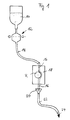
- FIG. 1 shows a bottle 10 in which a liquid to be administered, such as a nutrient or a medicament, is contained.
- a liquid to be administered such as a nutrient or a medicament
- the delivery rate is monitored with a drop sensor 12 of conventional design.
- a drop sensor 12 of conventional design.
- the liquid is guided to the pump 18 essentially vertically downwards, ie in the direction of gravity.
- the hose segment 16 leading through the pump 18, in contrast to the hose 14, is made of silicone.
- a valve 20 is arranged downstream of the pump 18 and will be described in more detail below.
- a further hose 22 connects to the valve 20 and, like the hose 14, is made of PVC and leads to the patient (not shown) in the direction of the arrow 24. Except for the valve 20, the device shown in FIG. 1 is of a conventional type.
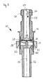
- FIG. 2 shows the valve 20 used in a device according to FIG. 1 in detail.
- the direction of flow of the liquid through the valve 20 is indicated by the arrow 26.
- the hose segment 16 made of silicone is connected upstream (not shown in FIG. 2, see FIG. 1).
- a part 30 of the pump 18 is indicated in FIG. 2 by the reference symbol 30 and by horizontal hatching.
- the valve 20 according to FIG. 2 is inserted into this part 30 of the pump 18.
- the PVC hose provided with the reference number 22 in FIG. 1 is connected to the valve 20 by means of a hose connection 32.
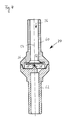
- FIGS. 2 and 3 Details of the valve 20 can be found in FIGS. 2 and 3, FIG. 2 showing the valve in the state mechanically coupled to the pump part 30, while FIG. 3 shows the valve in a state in which it can be used without a pump.
- a device in the form of a sliding ring 34 is axially displaceable and is in an upper position in the state shown in FIG. 2.
- a membrane 36 which forms the opening and closing member of the valve, is acted upon centrally by a mandrel 38.
- the opening pressure of the valve 20 is determined by the elasticity of the membrane 36. If the pressure difference in the direction of arrow 26 on the membrane 36 exceeds its pressing force against the valve seat 52, the membrane 36 bends out of the closed position shown in FIG.
- a bellows 42 of the valve 20 is necessary due to a form-fitting adaptation to the pump part 30 in the spread position, in which the mandrel 38 axially in comparison with the state shown in FIG the membrane 36 is displaced and the membrane presses against the valve seat 52 with a greater force, so that the opening pressure of the valve in the state shown in FIG. 2 is greater than in the state according to FIG. 3.
- the slide ring 34 is also positively fitted into the pump part 30 in such a way that it releases the bellows 42 into the spread position.
- the sliding ring 34 abuts against a flange 46 of the hose segment connection 28, which in turn is clamped between the sliding ring 34 and a stop 48 of the pump part 30.
- a recess 54 is provided, in which the pushed-on silicone hose segment 16 can be fastened by means of a locking ring.
- valve 20 can be used in the parenteral administration of fluid without the use of a pump 18, the fluid being delivered only by its own gravity.
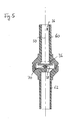
- FIG. 4 has an upper part 60 and a lower part 62.
- the annular valve seat 52 is formed on the upper part 60, while the mandrel 38 is formed on the lower part 62. Both in the closed state and in the open state it is ensured that the membrane 36 is mounted on two radially spaced points, so that a radial displacement of the membrane in the direction of the adjacent walls is avoided.
- a pin 68 is also provided on the membrane 36, which engages in a complementary recess in the mandrel 38 and thus reliably centers the membrane 36.
- the valve shown in FIG. 4 can be used generally for medical purposes, in particular for the administration of liquids.
- the membrane 36 is provided with an annular projection 70 which forms a recess into which the mandrel 38 engages in order to secure the membrane in a central position.
Landscapes
- Health & Medical Sciences (AREA)
- Engineering & Computer Science (AREA)
- General Engineering & Computer Science (AREA)
- Heart & Thoracic Surgery (AREA)
- Life Sciences & Earth Sciences (AREA)
- Vascular Medicine (AREA)
- Anesthesiology (AREA)
- Biomedical Technology (AREA)
- Mechanical Engineering (AREA)
- Hematology (AREA)
- Emergency Medicine (AREA)
- Animal Behavior & Ethology (AREA)
- General Health & Medical Sciences (AREA)
- Public Health (AREA)
- Veterinary Medicine (AREA)
- Infusion, Injection, And Reservoir Apparatuses (AREA)
- Pipeline Systems (AREA)
- Fluid-Pressure Circuits (AREA)
- Details Of Reciprocating Pumps (AREA)
Description
- Die Erfindung betrifft eine Vorrichtung zur parenteralen Verabreichung von Flüssigkeit.
- Bei der parenteralen Ernährung eines Patienten werden die Nährstoffe unter Umgehung des Magen/Darm-Traktes direkt in eine Vene gegeben. Neben Nährstoffen können auf diese Weise auch kontinuierlich Arzneimittel in den Blutkreislauf gebracht werden.
- Vorrichtungen für die parenterale Verabreichung von Flüssigkeiten weisen im allgemeinen eine Vorratsflasche für die Flüssigkeit auf, aus welcher die Flüssigkeit dosiert über einen elastischen Schlauch zu einer Injektionsnadel geführt wird, die direkt in eine Vene mündet. Die Förderung der Flüssigkeit durch den Schlauch erfolgt über eine Pumpe und/oder die Schwerkraft der Flüssigkeit.
- Vorrichtungen zur parenteralen Verabreichung von Flüssigkeiten müssen zum Schutz des Patienten hohen Sicherheitsanforderungen genügen. Insbesondere muß unter allen Umständen gewährleistet sein, daß die Förderrate, also die dem Patienten pro Zeiteinheit verabreichte Flüssigkeitsmenge, welche üblicherweise in Volumen pro Zeiteinheit oder Tropfen pro Zeiteinheit angegeben wird, einen vorgegebenen Grenzwert nicht überschreitet. Eine den Grenzwert überschreitende Mehrförderung könnte tödlich sein. Daneben darf auf keinen Fall Luft in die Vene des Patienten gelangen.
- Herkömmliche Vorrichtungen zur parenteralen Verabreichung von Flüssigkeiten weisen deshalb einen hohen Aufwand an Sicherheitseinrichtungen auf. Die Sicherheitseinrichtungen betreffen in erster Linie die sogenannten "ersten Fehler". Unter einem "ersten Fehler" wird das Versagen eines Schutz- oder Überwachungssystems verstanden, das zu einer unmittelbaren Gefahr für die Sicherheit des Patienten werden kann.
- Dringt Luft in den Zuführschlauch, so muß die Vorrichtung innerhalb einer Zeitspanne die Förderung von Flüssigkeit in die Vene einstellen, die kürzer ist als die Zeitspanne, in der die Luft zur Injektionsnadel gelangt. Die Zeitspanne vom Zeitpunkt des Auftretens eines Fehlers, wie z.B. das Eindringen von Luft in den Schlauch, bis zum Eintreten des sicheren Zustandes, also z.B. der Beendigung der Förderung, wird "Fehlerreaktionszeit" genannt. Die Fehlerreaktionszeit muß in jedem Fall so kurz sein, daß eine Gefährdung des Patienten bei Auftreten des Fehlers ausgeschlossen ist.
- Zur Vermeidung von Luft-Förderung sind im Stand der Technik Luftsensoren bekannt, die Alarm geben, sobald Luft im zum Patienten führenden Schlauch auftritt. Ultraschalleinrichtungen und Lichtschranken sind als Luftsensoren bekannt. Diese Vorrichtungen sind relativ aufwendig und haben überdies den Nachteil, daß sie nur "diagnostizieren", also nicht positiv das Eintreten von Luft verhindern, und somit die Verfügbarkeit der Vorrichtung nicht verbessern.
- Besonders beim Einsatz einer Förder-Pumpe im Zuführschlauch tritt das Problem des Lufteintritts in den Schlauch auf. Solche Pumpen sind z.B. aus der DE-PS 31 38 267 bekannt. In ihnen werden Silikon-Schläuche eingesetzt, wobei allerdings das Silikon für Luft permeabel ist, so daß dann, wenn der Druck im Inneren des Schlauches kleiner ist als der Druck in der umgebenden Luft (Atmosphäre), Gase in das Schlauchinnere eindringen können, was die bereits geschilderten fatalen Folgen hätte.
- Bei bekannten Vorrichtungen zur parenteralen Verabreichung von Flüssigkeiten kann ein Unterdruck im von der Förder-Pumpe beaufschlagten Silikonschlauch durch zwei Ursachen bedingt sein: Zum einen kann bei einer Okklusion des Schlauches im Bereich der Pumpe die abwärts in Richtung auf den Patienten "hängende" Flüssigkeitssäule einen Unterdruck, insbesondere im oberen Teil des Schlauches unmittelbar unterhalb der Okklusionsstelle erzeugen und zum anderen kann es in bestimmten Arbeitsphasen der Pumpe, auf die hier nicht näher eingegangen zu werden braucht, jeweils kurzzeitig periodisch zu einem Unterdruck im Silikonschlauch stromab der Pumpe kommen.
- Aus der US-A 4 210 173 ist eine Injektionsspritze für medizinische Flüssigkeiten bekannt, die ein Einlaßventil und ein Auslaßventil aufweist. Jedes Ventil hat eine flexible scheibenförmige Membran, die auf einer Seite von einem mittig angreifenden Dorn gegen einen auf der gegenüberliegenden Seite angeordneten, ringförmigen Ventilsitz gedrückt wird, so daß die Membran gegen den Ventilsitz vorgespannt ist. Vorzugsweise ist die Membran des Auslaßventils stärker vorgespannt als die Membran des Einlaßventils, so daß die beim Ansaugen von Flüssigkeit zu überwindende Kraft reduziert ist.
- Der Erfindung liegt die Aufgabe zugrunde, eine Vorrichtung zur parenteralen Verabreichung von Flüssigkeit, bei der die Flüssigkeit mittels einer Pumpe durch einen elastischen Schlauch und ein stromab der Pumpe im Schlauch angeordnetes Ventil zum Patienten gefördert wird, derart weiterzubilden, daß das Ventil auch ohne Pumpe in einer lediglich schwerkraftgespeisten Vorrichtung zur parenteralen Verabreichung von Flüssigkeit einsetzbar ist. Bei einem Einsatz des Ventils mit der Pumpe soll gewährleistet sein, daß keine Luft in den Schlauch eintritt.
- Erfindungsgemäß ist diese Aufgabe dadurch gelöst, daß an dem Ventil eine Einrichtung vorgesehen ist, mit der zwei unterschiedliche Öffnungsdrücke des Ventils einstellbar sind.
- Bei der erfindungsgemäßen Vorrichtung ist gewährleistet, daß der Druck im Inneren des Schlauches weder durch den Sog einer "hängenden Flüssigkeitssäule" noch durch bestimmte Arbeitsphasen der Pumpe, in denen sie kurzzeitig gegen die Förderrichtung ansaugt, kleiner ist als der Stickstoff-Partialdruck der den Schlauch umgebenden Atmosphäre. Ein Eindringen von Gasen in den Schlauch ist somit positiv ausgeschlossen, da im Silikon-Schlauchsegment bis zum Ventil immer ein hinreichend großer Druck herrscht.
- Auch wird durch diese Ausbildung der sogenannte "freeflow" (das freie Durchlaufen der Flüssigkeit durch den Schlauch in die Vene) verhindert.
- Durch die mittels der Einrichtung einstellbaren unterschiedlichen Öffnungsdrücke kann das Ventil ersatzweise, etwa bei einem Versagen der Pumpe, auch in einer nur schwerkraftgespeisten Vorrichtung zur parenteralen Verabreichung von Flüssigkeit eingesetzt werden.
- In einer bevorzugten Ausgestaltung der Erfindung ist vorgesehen, daß die Einrichtung bei Einsatz des Ventils mit einer Förderpumpe mit dieser mechanisch so gekoppelt ist, daß der höhere der beiden Öffnungsdrücke eingestellt ist.
- Das durch die Erfindung bereitgestellte Ventil ist auch unabhängig vom vorstehend beschriebenen Einsatz bei der parenteralen Verabreichung von Flüssigkeiten für andere medizinische Zwecke einsetzbar und zeichnet sich durch einen einfachen Aufbau und damit eine kostengünstige Herstellung sowie eine hohe Funktionssicherheit aus. Das Ventil ermöglicht die Einstellung von extrem kleinen Öffnungsdrucken.
- Aus der EP 0182045 ist zwar ein Rückschlag-Ventil bekannt, mit dem sehr kleine Öffnungsdrucke möglich sind, doch wird dort die elastische Membran auf ihrer vom Vertilsitz abgekehrten Seite von zwei Dornen beaufschlagt. Die Herstellung eines mit zwei Dornen versehenen Ventilteiles ist aufwendig und überdies erfordert der Ventil-Aufbau gemäß der EP 182045 eine zweilagige Membran.
- Das erfindungsgemäße Ventil, bei dem die Membran auf ihrer vom Ventilsitz abgekehrten Seite zumindest annähernd zentrisch von einem einzigen Dorn beaufschlagt ist, zeichnet sich dadurch aus, daß in jedem Betriebszustand (also bei offenem oder geschlossenem Ventil) immer eine Zwei-Punkt- Lagerung gewährleistet ist, so daß keine radiale Verschiebung der Membran möglich ist. Die Membran bleibt also zentriert und kann nicht mit den sie radial umgebenden Wandungen in Eingriff kommen, was zu Reibung und Funktionsbeeinträchtigungen führen könnte.
- Das erfindungsgemäße Ventil gewährleistet auch bei geringsten Druckdifferenzen im Bereich von wenigen Zentimetern Wassersäule ein einwandfreies Funktionieren sowohl bezüglich der Öffnungsfunktion als auch bezüglich der Schließfunktion.
- In einer bevorzugten Ausgestaltung des Rückschlag-Ventils ist vorgesehen, daß der zentrale Dorn axial verschiebbar ist, so daß die Vorspannung der Membran und damit der Öffnungsdruck des Ventils veränderbar ist.
- Es ist auch möglich, zwischen dem Dorn und der Membran eine Führung vorzusehen, beispielsweise in Form eines axialen Stiftes auf der Membran, der axial in eine Ausnehmung des Dornes eindringt, so daß ein Verrutschen der Membran in radialer Richtung positiv ausgeschlossen ist.
- Nachfolgend werden Ausführungsbeispiele der Erfindung anhand der Zeichnung näher erläutert. Es zeigt:
- Fig. 1
- schematisch eine Vorrichtung zur parenteralen Verabreichung von Flüssigkeit;
- Fig. 2
- ein bei einer Vorrichtung gemäß Fig. 1 eingesetztes Ventil, das mit einer Pumpe gekoppelt ist;
- Fig. 3
- ein Ventil gemäß Fig. 2, welches ohne Pumpe eingesetzt wird; und
- Fig. 4
- sowie Fig. 5 abgewandelte Ausführungsformen des Ventils.
- Fig. 1 zeigt eine Flasche 10, in der eine zu verabreichende Flüssigkeit, wie ein Nährmittel oder eine Arznei, enthalten ist. Mit einem Tropfensensor 12 herkömmlicher Bauart wird die Förderrate überwacht. Mittels eines elastischen Schlauches 14 aus PVC wird die Flüssigkeit im wesentlichen vertikal abwärts, also in Richtung der Schwerkraft, zur Pumpe 18 geführt. Das durch die Pumpe 18 führende Schlauchsegment 16 ist im Unterschied zum Schlauch 14 aus Silikon. Stromab der Pumpe 18 ist ein Ventil 20 angeordnet, welches weiter unten näher beschrieben werden wird. An das Ventil 20 schließt ein weiterer Schlauch 22 an, der wie der Schlauch 14 aus PVC besteht und in Richtung des Pfeiles 24 zum Patienten (nicht gezeigt) führt. Bis auf das Ventil 20 ist die in Fig. 1 gezeigte Vorrichtung von herkömmlicher Art.
- Fig. 2 zeigt das in einer Vorrichtung gemäß Fig. 1 verwendete Ventil 20 im Detail. Die Strömungsrichtung der Flüssigkeit durch das Ventil 20 ist durch der Pfeil 26 angedeutet.
- Am Schlauchsegmentanschluß 28 ist stromauf das Schlauchsegment 16 aus Silikon angeschlossen (in Fig. 2 nicht gezeigt, siehe Fig. 1).
- In Fig. 2 ist mit dem Bezugszeichen 30 und durch horizontale Schraffur ein Teil 30 der Pumpe 18 angedeutet. In dieses Teil 30 der Pumpe 18 wird das Ventil 20 gemäß Fig. 2 eingeschoben. Mittels eines Schlauchanschlusses 32 wird der in Fig. 1 mit dem Bezugszeichen 22 versehene PVC-Schlauch an das Ventil 20 angeschlossen.
- Einzelheiten des Ventils 20 sind den Fig. 2 und 3 zu entnehmen, wobei Fig. 2 das Ventil in mit dem Pumpenteil 30 mechanisch gekoppeltem Zustand zeigt, während Fig. 3 das Ventil in einem Zustand zeigt, in dem es ohne Pumpe einsetzbar ist.
- Eine Einrichtung in Form eines Schieberings 34 ist axial verschiebbar und befindet sich bei dem in Fig. 2 gezeigten Zustand in einer oberen Stellung. Eine das Öffnungs- und Schließorgan des Ventils bildende Membran 36 aus Silikon wird zentrisch von einem Dorn 38 beaufschlagt. Der Öffnungsdruck des Ventils 20 wird durch die Elastizität der Membran 36 bestimmt. Übersteigt die Druckdifferenz in Richtung des Pfeiles 26 an der Membran 36 deren Andrückkraft gegen den Ventilsitz 52, so verbiegt sich die Membran 36 aus der in Fig. 2 gezeigten Schließstellung heraus nach unten und öffnet einen Durchlaß über den Kanal 40 in das Schlauchanschlußstück 32. Beim in Fig. 2 gezeigten Einbauzustand in das Pumpenteil 30 ist ein Balg 42 des Ventils 20 notwendig aufgrund einer formschlüssigen Anpassung an das Pumpenteil 30 in der gespreizten Stellung, in welcher der Dorn 38 im Vergleich mit dem in Fig. 3 gezeigten Zustand axial in Richtung auf die Membran 36 verschoben ist und die Membran mit einer größeren Kraft gegen den Ventilsitz 52 drückt, so daß der Öffnungsdruck des Ventils beim in Fig. 2 gezeigten Zustand größer ist als beim Zustand gemäß Fig. 3.
- Neben dem Balg 42 ist auch der Schiehering 34 derart formschlüssig in das Pumpenteil 30 eingepaßt, daß er den Balg 42 in die Spreizlage freigibt. Der Schiebering 34 stößt dabei oben gegen einen Flansch 46 des Schlauchsegmentanschlusses 28, welcher seinerseits zwischen dem Schiebering 34 und einem Anschlag 48 des Pumpenteiles 30 eingeklemmt ist.
- Am oberen Teil des Schlauchsegmentanschlusses 28 ist eine Ausnehmung 54 vorgesehen, in welcher das aufgeschobene Silikon-Schlauchsegment 16 mittels eines Sicherungsringes befestigbar ist.
- Beim in Fig. 3 gezeigten Zustand des Ventils 20 sichert der Schiebering 34 die Streckstellung des Balges 42, wodurch der Dorn 38 in Richtung der Ventilachse 50 abwärts geschoben ist und die Andrückkraft der Membran 36 gegen den Ventilsitz 52 im Vergleich mit der in Fig. 2 gezeigten Stellung verringert ist.
- Im in Fig. 3 gezeigten Zustand kann das Ventil 20 bei der Parenteralen Verabreichung von Flüssigkeit ohne Verwendung einer Pumpe 18 verwendet werden, wobei die Flüssigkeit nur durch ihre eigene Schwerkraft gefördert wird.
- In den Fig. 4 und 5 sind weitere Ausführungsformen der Membran 36 und des Dorns 38 geseigt, wobei der Einfachheit halber auf eine Darstellung der Einrichtung 34, mittels derer die beiden unterschiedlichen Öffnungsdrücke einstellbar sind, versichtet wurde. Dem Ausführungsbeispiel gemäß den Fig. 2 und 3 entsprechende Bauteile sind mit gleichen Bezugszeichen versehen. Das in Fig. 4 gezeigte Ventil weist ein Oberteil 60 und ein Unterteil 62 auf. Am Oberteil 60 ist der ringförmige Ventilsitz 52 ausgeformt, während am Unterteil 62 der Dorn 38 ausgebildet ist. Sowohl im Schließzustand als auch im Öffnungszustand ist gewährleistet, daß die Membran 36 auf zwei radial beabstandeten Punkten gelagert ist, so daß eine radiale Verschiebung der Membran in Richtung auf die benachbarten Wände vermieden ist. Beim in Fig. 4 gezeigten Ausführungsbeispiel ist zusätzlich zu dieser Sicherung der Membran noch ein Stift 68 auf der Membran 36 vorgesehen, welcher in eine komplementäre Ausnehmung im Dorn 38 eingreift und so die Membran 36 zuverlässig zentriert.
- Das in Fig. 4 gezeigte Ventil ist allgemein für medizinische Zwecke verwendbar, insbesondere für die Verabreichung von Flüssigkeiten.
- In Fig. 5 ist, die Membran 36 mit einem ringförmigen Vorsprung 70 versehen, der eine Ausnehmung bildet, in welche der Dorn 38 eingreift, um die Membran in zentrischer Stellung zu sichern.
Claims (8)
- Vorrichtung zur parenteralen Verabreichung von Flüssigkeit mit einer die Flüssigkeit durch einen elastischen Schlauch (14, 16, 22) zum Patienten fördernden Pumpe (18), wobei stromab der Pumpe (18) ein Ventil (20) im Schlauch (16, 22) angeordnet ist, das in Patientenrichtung (24) unter einem Druck öffnet, der so groß ist, daß der Druck im Schlauch vor dem Ventil mindestens so groß ist wie der äußere Luftdruck,
dadurch gekennzeichnet, daß an dem Ventil (20) eine Einrichtung (34) vorgesehen ist, mit der zwei unterschiedliche Öffnungsdrucke des Ventils (20) einstellbar sind. - Vorrichtung nach Anspruch 1,
dadurch gekennzeichnet, daß die Einrichtung (34) bei Einsatz des Ventils (20) mit der Pumpe (18) mit dieser mechanisch so gekoppelt ist, daß der höhere der beiden einstellbaren Öffnungsdrücke wirksam ist. - Vorrichtung nach einem der Ansprüche 1 oder 2,
dadurch gekennzeichnet, daß das Ventil (20) eine gegen seine Öffnungsrichtung vorgespannte, elastische Membran (36) aufweist, wobei der Öffnungsdruck in Abhängigkeit von der Vorspannung variierbar ist. - Vorrichtung nach Anspruch 3,
dadurch gekennzeichnet, daß die Membran (36) plättchenförmig ist und im Schließzustand des Ventils (20) auf einem kreisförmigen Ventilsitz (52) aufliegt. - Vorrichtung nach einem der Ansprüche 3 oder 4,
dadurch gekennzeichnet, daß die Membran (36) auf ihrer vom Ventilsitz (52) abgekehrten Seite zumindest annähernd zentrisch von einem Dorn (38) beaufschlagt ist, der längs der Ventilachse (50) verschiebbar und in verschiedenen Stellungen arretierbar ist. - Vorrichtung nach Anspruch 5,
dadurch gekennzeichnet, daß die Membran (36) von dem Dorn (38) mittels einer Führung in zentrischer Lage gehalten wird. - Vorrichtung nach einem der Ansprüche 3 bis 6,
dadurch gekennzeichnet, daß die Membran (36) einstückig aus Silikon besteht. - Vorrichtung nach einem der Ansprüche 3 bis 7,
dadurch gekennzeichnet, daß die Membran (36) mit einer Ausnehmung oder einem ringförmigen Vorsprung (70) versehen ist, in welche bzw. welchen ein Dorn (38) eingreift.
Priority Applications (1)
| Application Number | Priority Date | Filing Date | Title |
|---|---|---|---|
| AT87115896T ATE91906T1 (de) | 1987-02-19 | 1987-10-29 | Vorrichtung zur verabreichung von fluessigkeit. |
Applications Claiming Priority (2)
| Application Number | Priority Date | Filing Date | Title |
|---|---|---|---|
| DE3705357 | 1987-02-19 | ||
| DE19873705357 DE3705357A1 (de) | 1987-02-19 | 1987-02-19 | Vorrichtung zur verabreichung von fluessigkeit |
Publications (3)
| Publication Number | Publication Date |
|---|---|
| EP0279028A2 EP0279028A2 (de) | 1988-08-24 |
| EP0279028A3 EP0279028A3 (en) | 1989-07-26 |
| EP0279028B1 true EP0279028B1 (de) | 1993-07-28 |
Family
ID=6321362
Family Applications (1)
| Application Number | Title | Priority Date | Filing Date |
|---|---|---|---|
| EP19870115896 Expired - Lifetime EP0279028B1 (de) | 1987-02-19 | 1987-10-29 | Vorrichtung zur Verabreichung von Flüssigkeit |
Country Status (5)
| Country | Link |
|---|---|
| US (1) | US4898581A (de) |
| EP (1) | EP0279028B1 (de) |
| AT (1) | ATE91906T1 (de) |
| DE (3) | DE3705357A1 (de) |
| ES (1) | ES2041667T3 (de) |
Families Citing this family (34)
| Publication number | Priority date | Publication date | Assignee | Title |
|---|---|---|---|---|
| DE3922291C1 (en) * | 1989-07-06 | 1990-11-08 | Pfrimmer-Viggo Gmbh & Co Kg, 8520 Erlangen, De | Medical non-return valve - has diaphragm moved against lip seal around valve axis |
| WO1995023002A1 (en) * | 1990-05-29 | 1995-08-31 | Paradis Joseph R | Control of fluid flow |
| US5226886A (en) * | 1991-12-06 | 1993-07-13 | Baxter International, Inc. | Ambulatory tubing set with anti-siphon valve |
| US5242423A (en) * | 1992-03-09 | 1993-09-07 | American Home Products Corporation | Needleless syringe |
| US5267964A (en) * | 1992-03-23 | 1993-12-07 | Clintec Nutrition Co. | Fluid control device including automatic valve |
| DE4309262C2 (de) * | 1992-12-23 | 2001-01-25 | Soellner Gmbh Medizinische Ein | Rückschlagventil bei Infusionsgeräten |
| US5405333A (en) * | 1992-12-28 | 1995-04-11 | Richmond; Frank M. | Liquid medicament bag with needleless connector fitting using boat assembly |
| US5334170A (en) | 1993-07-14 | 1994-08-02 | Abbott Laboratories | Dye management system including an administration set with an in-line burette |
| US6206860B1 (en) | 1993-07-28 | 2001-03-27 | Frank M. Richmond | Spikeless connection and drip chamber with valve |
| US5848994A (en) * | 1993-07-28 | 1998-12-15 | Richmond; Frank M. | IV sets with needleless spikeless fittings and valves |
| US5623969A (en) * | 1995-06-07 | 1997-04-29 | B. Braun Medical Inc. | Normally closed aspiration valve |
| DE29520388U1 (de) * | 1995-12-22 | 1997-04-24 | Frör, Werner, 91052 Erlangen | Rohrförmiges Leitungsteil mit einem Schwimmerventil und Formwerkzeug zum Herstellen desselben |
| US6106502A (en) * | 1996-12-18 | 2000-08-22 | Richmond; Frank M. | IV sets with needleless fittings and valves |
| IL120651A (en) * | 1997-04-11 | 2001-06-14 | Nestle Sa | Administration of liquid to a patient |
| DE19749562C1 (de) * | 1997-11-10 | 1999-04-22 | Jan Willem Marinus Ing Myers | Infusionsbesteck |
| US6013060A (en) * | 1997-11-19 | 2000-01-11 | Woodard; Robert W. | Intravenous liquid flow regulator |
| US6193689B1 (en) | 1997-11-19 | 2001-02-27 | Robert W. Woodard | Intravenous liquid flow regulator |
| US5992462A (en) * | 1998-10-28 | 1999-11-30 | Vernay Laboratories, Inc. | Disc type check valve |
| US20040222229A1 (en) * | 2003-05-06 | 2004-11-11 | Gabbard Mark E. | Valve for dispensing liquids and method of use |
| US9241735B2 (en) | 2003-12-05 | 2016-01-26 | Onset Medical Corporation | Expandable percutaneous sheath |
| US7794436B2 (en) * | 2004-01-13 | 2010-09-14 | Lloyd Jay Pinel | Controlled gastric bolus feeding device |
| US7794423B2 (en) * | 2004-05-25 | 2010-09-14 | Covidien Ag | Re-certification system for a flow control apparatus |
| US7462170B2 (en) * | 2004-05-25 | 2008-12-09 | Covidien Ag | Administration feeding set and valve mechanism |
| WO2007047795A2 (en) * | 2005-10-20 | 2007-04-26 | Richmond Frank M | Connector/device with reflux valves |
| DE102007010412B4 (de) * | 2007-02-13 | 2020-07-30 | Endress+Hauser Conducta Gmbh+Co. Kg | Vorrichtung und Verfahren zum Dosieren von Flüssigkeiten in gasgefüllte Räume |
| DE102008020820A1 (de) | 2008-04-25 | 2009-10-29 | Fritz Giebler Gmbh | Sicherheitsventil für einen Infusionsschlauch |
| EP2218476B2 (de) | 2009-02-11 | 2022-03-16 | F. Hoffmann-La Roche AG | Blattfederventil und Konusmembranventil |
| ES1076535Y (es) * | 2011-12-12 | 2012-06-18 | Gonzalez Antonio Gonzalez | Dispositivo de cerrado para el rellenado de la camara de goteo de los equipos de seguridad durante la administracion de citostaticos con conexion a bomba |
| JP6123407B2 (ja) * | 2013-03-26 | 2017-05-10 | 株式会社ジェイテクト | 電動パワーステアリング装置 |
| DE102017102586A1 (de) * | 2017-02-09 | 2018-08-09 | Eagle Actuator Components Gmbh & Co. Kg | Rückschlagventil |
| GB2560342A (en) * | 2017-03-08 | 2018-09-12 | Product4 Ltd | Valve |
| US11598434B2 (en) | 2020-01-17 | 2023-03-07 | Life Technologies Corporation | Umbrella check valve assembly having retention plate |
| USD1055279S1 (en) | 2023-04-17 | 2024-12-24 | iMed Technology, Inc. | Feeding tube set inlet component |
| USD1069109S1 (en) | 2023-04-17 | 2025-04-01 | iMed Technology, Inc. | Feeding tube set inlet component |
Family Cites Families (13)
| Publication number | Priority date | Publication date | Assignee | Title |
|---|---|---|---|---|
| BE775758A (fr) * | 1971-02-12 | 1972-03-16 | American Hospital Supply Corp | Ensemble d'administration medical et procede de distribution deplusieurs liquides medicaux |
| US4210173A (en) * | 1976-12-06 | 1980-07-01 | American Hospital Supply Corporation | Syringe pumping system with valves |
| IL52266A (en) * | 1977-06-07 | 1979-12-30 | Leibinsohn Saul | Microbe barrier device |
| US4223813A (en) * | 1978-02-17 | 1980-09-23 | Baxter Travenol Laboratories, Inc. | Noncritically aligned valving devices for flow rate-limiting cassettes used in intravenous solution administering equipment |
| US4354492A (en) * | 1979-04-16 | 1982-10-19 | American Hospital Supply Corporation | Medical administration set with backflow check valve |
| US4453931A (en) * | 1980-08-01 | 1984-06-12 | Oximetrix, Inc. | Intravenous metering device |
| DE3035748C2 (de) * | 1980-09-22 | 1986-01-02 | Siemens AG, 1000 Berlin und 8000 München | Infusionsgerät |
| DE3138267C2 (de) * | 1981-09-25 | 1985-05-30 | Pfrimmer-Viggo GmbH & Co KG, 8520 Erlangen | Vorrichtung zur enteralen Verabreichung von Nahrung |
| US4550749A (en) * | 1984-03-12 | 1985-11-05 | C. R. Bard, Inc. | Adjustable check valve |
| US4615693A (en) * | 1984-03-27 | 1986-10-07 | Nypro Inc. | Administration of fluids |
| US4535820A (en) * | 1984-05-24 | 1985-08-20 | Burron Medical Inc. | Normally closed check valve |
| US4556086A (en) * | 1984-09-26 | 1985-12-03 | Burron Medical Inc. | Dual disc low pressure back-check valve |
| US4684366A (en) * | 1985-03-15 | 1987-08-04 | Denny Christopher G | Syringe for the remote injection of animals and fish |
-
1987
- 1987-02-19 DE DE19873705357 patent/DE3705357A1/de not_active Withdrawn
- 1987-10-29 EP EP19870115896 patent/EP0279028B1/de not_active Expired - Lifetime
- 1987-10-29 ES ES87115896T patent/ES2041667T3/es not_active Expired - Lifetime
- 1987-10-29 DE DE8787115896T patent/DE3786780D1/de not_active Expired - Lifetime
- 1987-10-29 AT AT87115896T patent/ATE91906T1/de not_active IP Right Cessation
- 1987-10-29 DE DE8717726U patent/DE8717726U1/de not_active Expired
-
1989
- 1989-06-05 US US07/364,546 patent/US4898581A/en not_active Expired - Lifetime
Also Published As
| Publication number | Publication date |
|---|---|
| DE3786780D1 (de) | 1993-09-02 |
| EP0279028A2 (de) | 1988-08-24 |
| DE3705357A1 (de) | 1988-09-01 |
| EP0279028A3 (en) | 1989-07-26 |
| DE8717726U1 (de) | 1989-10-19 |
| US4898581A (en) | 1990-02-06 |
| ATE91906T1 (de) | 1993-08-15 |
| ES2041667T3 (es) | 1993-12-01 |
Similar Documents
| Publication | Publication Date | Title |
|---|---|---|
| EP0279028B1 (de) | Vorrichtung zur Verabreichung von Flüssigkeit | |
| DE3871721T2 (de) | Vorrichtung und verfahren zum nachweisen einer partiellen okklusion. | |
| EP0432425B1 (de) | Vorrichtung zur Infusion | |
| DE69805944T2 (de) | Pumpsystem mit fehlerdetektion für die klinische ernährung | |
| DE60035445T2 (de) | Kontrollverfahren für peristaltische Pumpe | |
| DE69020832T2 (de) | Mit Ultraschall arbeitender Luftmengendetektor für ein Medikamenten-Infusionssystem. | |
| DE69328271T2 (de) | Flüssigkeitssteuervorrichtung mit automatischen Ventil | |
| DE69720744T2 (de) | Ventil zum gebrauch mit einer intravenösen vorrichtung | |
| EP0515597B1 (de) | Rückschlagventil, insbesondere für medizinische infusionsgeräte | |
| DE69023995T2 (de) | Automatischer Schlauchverschluss zum Verbinden mit einem Ultraschallsensor. | |
| DE69214771T2 (de) | Steuervorrichtung zum Ein- und Ausschalten einer Pumpe in einem Wasserversorgungsnetz | |
| EP1061978B1 (de) | Injektor zur applizierung von flüssigkeiten, insbesondere von kontrastmitteln für die röntgen- und kernspintomographie | |
| DE2649813A1 (de) | Ausfallsichere mehrfachventil-pumpenvorrichtung | |
| DE69807647T2 (de) | Vorrichtung zur verabreichung von zwei flüssigkeiten | |
| WO1995003079A1 (de) | Vorrichtung zur infusionsüberwachung | |
| DE2145421A1 (de) | Verfahren und Vorrichtung zur Regelung des Flüssigkeitsflusses | |
| DE4137837C1 (de) | ||
| DE60204754T2 (de) | Verfahren und vorrichtung zum füllen von kapseln nadelloser injektoren | |
| DE69101654T2 (de) | Detektor für den Abfluss einer ersten Flüssigkeit im Kreislauf einer zweiten Flüssigkeit. | |
| DE19642234C1 (de) | Implantierbare Infusionspumpe | |
| DE2051639A1 (de) | Intravenöse Infusionsvorrichtung | |
| EP4204038A1 (de) | Infusions- oder transfusionsbesteck und system umfassend ein infusions- oder transfusionsbesteck | |
| EP3096818B1 (de) | Verfahren und vorrichtung zur kontrolle des durchflusses durch eine medizinische infusionsleitung | |
| DD243858A1 (de) | Injektionsventil | |
| DE4205718C2 (de) | Einrichtung zur gleichzeitigen Infusion mehrerer Infusionsflüssigkeiten in einen Patienten |
Legal Events
| Date | Code | Title | Description |
|---|---|---|---|
| PUAI | Public reference made under article 153(3) epc to a published international application that has entered the european phase |
Free format text: ORIGINAL CODE: 0009012 |
|
| AK | Designated contracting states |
Kind code of ref document: A2 Designated state(s): AT DE ES FR GB IT SE |
|
| PUAL | Search report despatched |
Free format text: ORIGINAL CODE: 0009013 |
|
| AK | Designated contracting states |
Kind code of ref document: A3 Designated state(s): AT DE ES FR GB IT SE |
|
| 17P | Request for examination filed |
Effective date: 19890706 |
|
| 17Q | First examination report despatched |
Effective date: 19910124 |
|
| RAP1 | Party data changed (applicant data changed or rights of an application transferred) |
Owner name: KABI PHARMACIA GMBH |
|
| GRAA | (expected) grant |
Free format text: ORIGINAL CODE: 0009210 |
|
| ITF | It: translation for a ep patent filed | ||
| AK | Designated contracting states |
Kind code of ref document: B1 Designated state(s): AT DE ES FR GB IT SE |
|
| REF | Corresponds to: |
Ref document number: 91906 Country of ref document: AT Date of ref document: 19930815 Kind code of ref document: T |
|
| GBT | Gb: translation of ep patent filed (gb section 77(6)(a)/1977) |
Effective date: 19930727 |
|
| REF | Corresponds to: |
Ref document number: 3786780 Country of ref document: DE Date of ref document: 19930902 |
|
| ET | Fr: translation filed | ||
| REG | Reference to a national code |
Ref country code: ES Ref legal event code: FG2A Ref document number: 2041667 Country of ref document: ES Kind code of ref document: T3 |
|
| PLBE | No opposition filed within time limit |
Free format text: ORIGINAL CODE: 0009261 |
|
| STAA | Information on the status of an ep patent application or granted ep patent |
Free format text: STATUS: NO OPPOSITION FILED WITHIN TIME LIMIT |
|
| 26N | No opposition filed | ||
| EAL | Se: european patent in force in sweden |
Ref document number: 87115896.0 |
|
| REG | Reference to a national code |
Ref country code: GB Ref legal event code: IF02 |
|
| PGFP | Annual fee paid to national office [announced via postgrant information from national office to epo] |
Ref country code: GB Payment date: 20060915 Year of fee payment: 20 Ref country code: AT Payment date: 20060915 Year of fee payment: 20 |
|
| PGFP | Annual fee paid to national office [announced via postgrant information from national office to epo] |
Ref country code: SE Payment date: 20061005 Year of fee payment: 20 |
|
| PGFP | Annual fee paid to national office [announced via postgrant information from national office to epo] |
Ref country code: ES Payment date: 20061023 Year of fee payment: 20 |
|
| PGFP | Annual fee paid to national office [announced via postgrant information from national office to epo] |
Ref country code: IT Payment date: 20061031 Year of fee payment: 20 Ref country code: DE Payment date: 20061031 Year of fee payment: 20 |
|
| REG | Reference to a national code |
Ref country code: GB Ref legal event code: PE20 |
|
| REG | Reference to a national code |
Ref country code: ES Ref legal event code: FD2A Effective date: 20071030 |
|
| PG25 | Lapsed in a contracting state [announced via postgrant information from national office to epo] |
Ref country code: ES Free format text: LAPSE BECAUSE OF EXPIRATION OF PROTECTION Effective date: 20071030 Ref country code: GB Free format text: LAPSE BECAUSE OF EXPIRATION OF PROTECTION Effective date: 20071028 |
|
| PGFP | Annual fee paid to national office [announced via postgrant information from national office to epo] |
Ref country code: FR Payment date: 20061003 Year of fee payment: 20 |