EP0277799B1 - Objekt-Positionierungssystem - Google Patents
Objekt-Positionierungssystem Download PDFInfo
- Publication number
- EP0277799B1 EP0277799B1 EP88300846A EP88300846A EP0277799B1 EP 0277799 B1 EP0277799 B1 EP 0277799B1 EP 88300846 A EP88300846 A EP 88300846A EP 88300846 A EP88300846 A EP 88300846A EP 0277799 B1 EP0277799 B1 EP 0277799B1
- Authority
- EP
- European Patent Office
- Prior art keywords
- data
- velocity
- tracking
- mode
- optical head
- Prior art date
- Legal status (The legal status is an assumption and is not a legal conclusion. Google has not performed a legal analysis and makes no representation as to the accuracy of the status listed.)
- Expired - Lifetime
Links
Images


Classifications
-
- G—PHYSICS
- G11—INFORMATION STORAGE
- G11B—INFORMATION STORAGE BASED ON RELATIVE MOVEMENT BETWEEN RECORD CARRIER AND TRANSDUCER
- G11B7/00—Recording or reproducing by optical means, e.g. recording using a thermal beam of optical radiation by modifying optical properties or the physical structure, reproducing using an optical beam at lower power by sensing optical properties; Record carriers therefor
- G11B7/08—Disposition or mounting of heads or light sources relatively to record carriers
- G11B7/085—Disposition or mounting of heads or light sources relatively to record carriers with provision for moving the light beam into, or out of, its operative position or across tracks, otherwise than during the transducing operation, e.g. for adjustment or preliminary positioning or track change or selection
-
- G—PHYSICS
- G11—INFORMATION STORAGE
- G11B—INFORMATION STORAGE BASED ON RELATIVE MOVEMENT BETWEEN RECORD CARRIER AND TRANSDUCER
- G11B21/00—Head arrangements not specific to the method of recording or reproducing
- G11B21/02—Driving or moving of heads
- G11B21/08—Track changing or selecting during transducing operation
- G11B21/081—Access to indexed tracks or parts of continuous track
- G11B21/083—Access to indexed tracks or parts of continuous track on discs
-
- G—PHYSICS
- G11—INFORMATION STORAGE
- G11B—INFORMATION STORAGE BASED ON RELATIVE MOVEMENT BETWEEN RECORD CARRIER AND TRANSDUCER
- G11B7/00—Recording or reproducing by optical means, e.g. recording using a thermal beam of optical radiation by modifying optical properties or the physical structure, reproducing using an optical beam at lower power by sensing optical properties; Record carriers therefor
- G11B7/08—Disposition or mounting of heads or light sources relatively to record carriers
- G11B7/085—Disposition or mounting of heads or light sources relatively to record carriers with provision for moving the light beam into, or out of, its operative position or across tracks, otherwise than during the transducing operation, e.g. for adjustment or preliminary positioning or track change or selection
- G11B7/08505—Methods for track change, selection or preliminary positioning by moving the head
- G11B7/08529—Methods and circuits to control the velocity of the head as it traverses the tracks
Definitions
- This invention relates to a positioning system for positioning an object which is to be quickly moved to a desired position and finely positioned at the desired position such as a head of random accessable recording equipment including an optical disc player and a head of printing equipment.
- Optical disc players have high density recording and high speed random access capability.
- Track pitch (in the form of either spiral or concentric tracks) of an optical disc is 1.6 ⁇ m or so.
- the optical disc player needs high resolution tracking control of an optical head.
- the optical head has to be moved rapidly across the tracks in a radial direction of the disc.
- the conventional optical disc player has two separate mechanisms - a tracking actuator for allowing the light spot to follow a track and a traversing actuator for moving the optical head to traverse the tracks.
- a tracking actuator for allowing the light spot to follow a track
- a traversing actuator for moving the optical head to traverse the tracks.
- a voice-coil-type linear motor is used as the traversing actuator with a velocity sensor usually installed therein.
- Kinetic velocity of the traversing actuator is sensed by the velocity sensor, and is fed back to a traversing control system. This constitutes a velocity feedback loop for stabilizing the positioning control of the optical head.
- An example of such apparatus is disclosed in Japanese published patent application No. 57-181436, published Nov. 8, 1982, entitled "Optical Disc Apparatus".
- US-A-4491776 An example of another system of this general type is shown in US-A-4491776.
- This document shows an optical disc apparatus in which an optical head is mounted on a carrier of a linear motor. Assembled in the optical head are a semiconductor laser oscillator, a focussing unit, a tracking unit and a signal detector for producing a focus error signal and a position error signal for effecting focussing and tracking respectively.
- a separate control mechanism controls the high speed movement of the optical head for permitting random access to data.
- control system made up by analog circuits cannot avoid DC offset and the thermal drift, which cause positioning errors.
- control system composed of analog circuits needs passive parts such as capacitors and resistors for building compensation filters for stabilizing the closed loop system. Even if the control system is mounted on a custom IC (integrated circuit), these passive parts must be mounted out of the IC as external parts. For this reason, the control system composed of analog circuits was an obstacle for realising low-cost and small-sized equipment.
- Another object of the present invention is to provide a positioning system for controlling an optical head of an optical disc player with a wide dynamic range in an address seeking mode and a high resolution in a tracking control mode.
- the present invention provides a positioning system for controlling an object which is to be moved quickly in a first, high speed moving mode and which is to be positioned finely at a desired position in a second, high positional resolution moving mode, said system comprising: a positioning detecting means for detecting an actual position of said object and for producing actual position data indicative of said actual position; a seek control means for comparing said actual position data with predetermined desired position data representing a desired position and for calculating position compensation data representing a difference between said actual position data and said desired position data, said seek control means outputting an address seeking command signal when said position compensation data is larger than a predetermined value; drive control data producing means for producing drive control data from said position compensation data; and a drive means responsive to said drive control data for moving said object, characterised in that said drive control data producing means comprises: a velocity detecting means for normally detecting a moving velocity of said object in a predetermined velocity range and being responsive to said address seeking command signal for decreasing its gain so as to detect said velocity coarsely in a wider velocity range than said predetermined
- the gain of the velocity sensor is decreased in response to the seek command to become operative in a wide velocity range.
- numerically processing circuitry is provided having a circuit whose gain is increased in response to the seek command to keep constant a total gain of the velocity feedback loop.
- This system can be effectively used for controlling an optical head of an optical disc player, which also has a velocity feedback loop.
- the seek controller produces position compensation data representing a position error of a traversing actuator from a goal position.
- the seek controller produces an address seeking command, which is applied to a position sensor or a numerating circuit for numerating an output signal of the position sensor for decreasing the numerated gain of the position sensor.
- the velocity feedback loop can operate with a wide dynamic range in an address seeking mode and with a high resolution in a track following mode.
- Fig. 1 shows a digitally controlled positioning system which has a velocity feedback loop operating in two control modes ⁇ a high resolution mode for a high resolution positioning of a controlled object and a high speed mode for a high speed movement of the object.
- the velocity feedback loop comprises a controlled object 1, a velocity detection unit 2, a velocity numerating unit 3, an addition unit 4, an operation unit 5, a voltage conversion unit 6 and a drive unit 7.
- the velocity detection unit 2 detects kinetic velocity of the controlled object 1 and outputs a velocity detection signal Sv.
- the velocity detection unit 2 may be a tachometer or a linear encoder installed in the controlled object 1 generating a frequency signal proportional to the kinetic velocity.
- the velocity numerating means 2 receives the velocity detection signal Sv and converts it into a digital velocity data Dv.
- the addition unit 4 receives the velocity data Dv and adds it to a position compensation data Dc(described later).
- An addition result Da is sent to the operation unit 5.
- the operation unit 5 filters the data Da to obtain a drive data Dd.
- the voltage conversion unit 6 converts the drive data Dd into a voltage signal.
- the voltage conversion unit 6 may be a digital to analog converter or a binary counter which modulates the drive data Dd into a pulse width of a voltage pulse.
- the drive unit 7 moves the controlled object 1 according to the voltage signal until the position compensation data Dc reduces to zero.
- the velocity numerating unit 3 has a limited resolution and a limited dynamic range in general. These two factors are restricted by each other. For example, an 8-bit analog to digital converter is limited its resolution as 1/255 of the dynamic range. There is no way to improve the resolution except for increasing the word length (from 8 bits to 16 bits, for example).
- a position detection unit 8 detects a current position of the controlled object 1 and outputs current position data Dp.
- a seek control unit 9 receives the current position data Dp and externally given goal data Dg representing a position which the controlled object 1 should reach, and produces from the goal data Dg and the current position data Dp position compensation data Dc which indicates a distance between the current position and the goal position. If the relative positional error is small, the controlled object 1 does not need to move fast, but if it is large the controlled object 1 should move as fast as possible. Therefore, if the value of the position compensation data Dc is larger than a predetermined value, the seek control unit 9 outputs a seek command Cs in addition to the position compensation data Dc to the velocity feedback loop. This state is the high speed mode.
- the position compensation data Dc is sent to the addition unit 4.
- the seek command Cs is sent to the velocity detection unit 2 and the operation unit 5.
- the velocity detection unit 2 In the high speed mode, the velocity detection unit 2 needs to have a wide dynamic range because the kinetic velocity of the controlled object 1 is large. To obtain the wide dynamic range, the velocity detection unit 2 decreases its gain in response to the seek command Cs. At the same time, the operation unit 5 increases its gain in response to the seek command Cs because the total loop gain of the velocity feedback loop should be fixed for its stability.
- the seek control unit 9 resets the seek command Cs. This state is the high resolution mode.
- the velocity detection unit 2 does not need a wide dynamic range but needs a high resolution because the kinetic velocity of the controlled object 1 is small enough but should be detected in high resolution. Therefore, the velocity detection unit 2 increases its gain and the operation unit 5 decreases its gain in response to the resetting of the seek command Cs to obtain the high resolution with the total loop gain of the velocity feedback loop being kept fixed for its stability.
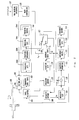
- Fig. 2 shows a schematic block diagram of a positioning system for an optical disc player embodying the present invention.
- the positioning system has two closed loops ⁇ a tracking control loop for track following and a traversing control loop for a traversing actuator.
- the tracking control loop comprises an optical head 101, a tracking error sensor 103, a tracking controller 104 and a tracking actuator 102. Relationship between the tracking actuator 102 and a traversing actuator 105 is illustrated in Fig. 3.
- the tracking actuator 102 drives an objective lens unit 101b movably mounted on a main body 101a of the optical head 101 via a damping element 101c to finely follow a track 100a formed on an optical disc 100.
- the traversing actuator 105 drives the main body 101a of the optical head 101 to roughly follow the track if the track is spiral or to move a large distance from one track to another, for example from the track 100a to another track 100b by traversing tracks located therebetween.
- the optical head 101 focuses a light beam on a track to form a light spot.
- a focusing control system which is not related to the present invention, is not illustrated.
- the tracking error sensor 103 produces a relative position signal indicative of a position of the light spot relative to a track from an intensity or phase error of a reflected light from the disc 100.
- the relative position signal is sent to the tracking controller 104.
- the tracking controller 104 comprises a tracking analog to digital (A/D) converter 104a, a tracking operator 104b, a tracking digital to analog (D/A) converter 104c, and a tracking driver 104d.
- the tracking A/D converter 104a converts the relative position signal to a digital relative position data Dr.
- the relative position data Dr is sent to the tracking operator 104b.
- the tracking operator 104b is a PID (proportional plus integral plus derivative) controller for stabilizing the tracking control loop. It filters the relative position data to obtain a tracking drive data Dt.
- the tracking drive data Dt is converted to a tracking voltage signal by the tracking D/A converter 104c.
- the tracking voltage signal is amplified by the tracking driver 104d, and applied to the tracking actuator 102 so that the tracking actuator 102 actuates the optical head 101 to follow a desired track.
- the traversing control loop comprises the traversing actuator 105, a position sensor 115, a position analog to digital (A/D) converter 116, an address seeking controller 106, a selector 107, a velocity sensor 108, a velocity analog to digital (A/D) converter 109, an adder 110, a traverse operator 111, a variable multiplier 112, a traverse digital to analog (D/A) converter 113, and a traverse driver 114.
- the traversing actuator 105 moves the optical head 101 across tracks on the optical disc 100.
- the position sensor 115 produces a current position signal indicative of an absolute position of the traversing actuator 105, for example, by counting pulses from a ladder-like linear scale (not illustrated) installed in the actuator 105.
- the position A/D converter 116 converts the current position signal from the position sensor 115 to a digital current position data Dp and sends the data Dp to the address seeking controller 106.
- the address seeking controller 106 compares the current position data Dp with a goal data Dg given from a main controller 118 of the optical disk player.
- the main controller 118 produces the goal data Dg from an instruction inputted by an operator via a man-machine interface 117 or a program previously prepared therein.
- the address seeking controller 106 outputs an address seeking command Sa and a position compensation data Dc corresponding to a difference between the goal data Dg and the current position data Dp.
- the selector 107 passes therethrough either the position compensation data Dc when the address seeking command Sa is outputted from the address seeking controller 106 or the tracking drive data Dt when the address seeking command Sa is not outputted. An output data from the selector 107 is fed to an input terminal 110a of the adder 110.
- the velocity sensor 108 detects a kinetic velocity of the traversing actuator 105, for example, by measuring the width of each of the pulses from the ladder-like linear scale, and outputs as a detection result a velocity signal Sv.
- the velocity A/D converter 109 converts the velocity signal Sv to a digital velocity data Dv.
- the adder 110 numerically adds the velocity data Dv to the output data (Dt or Dc) from the selector 107, and sends an addition result to the traverse operator 111.
- the traverse operator 111 is a known digital filter which executes z-transformation or Tustin's bilinear method to filter the output data of the adder 110.
- the filtered output data of the traverse operator 111 is multiplied by a predetermined coefficient in the variable multiplier 112.
- the traverse D/A converter 113 converts an output data of the variable multiplier 112 to a voltage signal, which is amplified by the traverse driver 114, and applied to the traverse actuator 114 for moving the optical head 101.
- the second closed loop containing the velocity sensor 108 and the velocity A/D converter 109 constitutes a velocity feedback loop whose control input is the terminal 110a of the adder 110 as illustrated in Fig. 1.
- This loop is the main block of the positioning system.
- the kinetic velocity of the traversing actuator 105 is proportional to the value of the data fed to the terminal 110a.
- the optical disc player has two operating modes ⁇ an address seeking mode, and a track following mode.
- the address seeking mode is for moving the optical head 101 to a desired track which has a desired address.
- the track following mode is for allowing the optical head 101 to follow the track after the address seeking mode.
- the main aim of the positioning system is to control the tracking actuator 102 so as to keep the position of the optical head 101 within an allowable deviation range from the center of a track.
- Fig. 4 shows a schematic flow chart showing the operation of the address seeking controller 106 in the address seeking mode.
- the goal data Dg is sent from the main controller 118 to the address seeking controller 106 in step 1.
- the address seeking controller 106 receives a current position data Dp from the position A/D converter 116 in step 2, and compares the current position data Dp with the goal data Dg in step 3. If the current position data Dp is not coincide with the goal data Dg, the address seeking controller 106 outputs a position compensation data Dc to the selector 107 in step 4, and concurrently outputs an address seeking command Sa to the selector 107, the velocity sensor 108 and the variable multiplier 112 in step 5.
- the selector 107 selects its input terminal B connected to the address seeking controller 106 so as to pass the position compensation data Dc, which is fed to the velocity feedback loop from the input terminal 110a of the adder 110.
- the traversing actuator 105 begins to move in response to the position compensation data Dc.
- the traversing actuator 105 should arrive at a track indicated by the goal data Dg as rapidly as possible in order to achieve high speed address seeking. Therefore, the velocity sensor 108 is required to detect a velocity in a wide velocity range. For this reason, the gain of the velocity sensor 108 is decreased in response to the address seeking command to detect a velocity in the wide velocity range.
- the range is at least 33 mm/sec, when the traversing actuator 105 is to move from the innermost track to the outermost track in 1 sec.
- detectable working range of the traverse A/D converter 109 is set up at least 33 mm/sec.
- the traverse A/D converter 109 can convert the kinetic velocity of the traversing actuator 105 to the velocity data Dv.
- the gain of the variable multiplier 112 is increased to keep constant the total gain of the feedback loop.
- the address seeking controller 106 repeats the process of steps 2 through 5 until the current position data becomes in coincidence with the goal data in step 3. When the current position data Dp coincides with the goal data Dg, the address seeking controller 106 resets the address seeking command Sa in step 6.
- the player is changed to the track following mode, in which the selector 107 selects its input terminal A connected to the tracking operator 104b.
- the velocity feedback loop is provided with the tracking operating data Dt from the input terminal 110a of the adder 110, and the traversing actuator 105 begins to obey the tracking operating data.
- the gain of the velocity sensor 108 is increased, and the coefficient of the variable multiplier 112 is decreased.
- the velocity A/D converter 109 rather needs a high resolution than the wide working range because the kinetic velocity in this mode is 0.015 mm/sec. in average, which is far smaller than 33mm/sec. in the address seeking mode.
- open loop gain of the velocity feedback loop is not changed, because the coefficient value of the variable multiplier 112 is decreased to balance the open loop gain of the velocity feedback loop in the address seeking mode with that in the track following mode.
- the limited word length of the velocity A/D converter 109 can be utilized effectively because the gains of the velocity sensor 108 and the variable multiplier 112 can be set according to the two operating modes of the player.
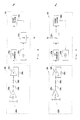
- Fig. 5 shows a schematic block diagram of a positioning system which is provided with a decoder 120 in place of the position sensor 115 and the position A/D converter 116 in Fig. 2.
- each data block recorder in the optical disc 100 includes an address data for identifying the position of the optical head 101.
- the decoder 120 extracts a current address data from the signal reproduced by the optical head 101, and converts the current address data into an absolute position data which is sent to the address seeking controller 106.
- the absolute position data is equivalent to the current position data Dp in Fig. 2. Therefore the operation and effect of the system shown in Fig. 5 are equivalent to those of the system shown in Fig.2.
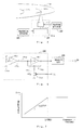
- Fig. 6 shows a circuit diagram of an exemplary configuration of the velocity sensor 108.
- the velocity sensor 108 comprises operational amplifiers 108a and 108i, a variable resistor 108b, a capacitor 108c, fixed resistors 108d, 108e, 108f and 108g, and an analog switch 108h.
- the variable resistor 108b is equipped in the traversing actuator 105, and varies in resistance according to the position of the traversing actuator 105.
- An output voltage of the operational amplifier 108i is proportional to the resistance of the variable resistor 108b.
- the capacitor 108c and the fixed resistor 108d constitute a high-pass filter.
- F(s) - s(Z/R1)/(1+sCR1) (1)
- C denotes a capacitance of the capacitor 108c
- R1 denotes a resistance of the fixed resistor 108d
- s denotes a Laplace operator
- Z denotes a synthetic resistance determined by the fixed resistors 108e, 108f and 108g.
- Fig. 7 shows a frequency response of the high-pass filter.
- the value CR1 limits the frequency range of derivative action in the filter as shown in Fig. 7. Therefore, when the value CR1 is set large enough relative to the frequency range of the input signal (the output voltage of the operational amplifier 108a), the eq. (1) can be rewritten equivalently as follows: F(s) ⁇ - s(Z/R1) (1)' Since the output voltage of the operational amplifier 108a is proportional to the position of the traversing actuator 105, the output voltage of the operational amplifier 108b is also proportional to the velocity of the traversing actuator 105.
- the analog switch 108h is closed in the track following mode, and opened in response to the address seeking command Sa in the address seeking mode. Therefore, the value of Z is as follows: where R denotes a resistance of each of the fixed resistors 108e and 108f, and R0 denotes a resistance of the fixed resistor 108g.
- the gain of the velocity sensor 108 increases in the track following mode and decreases in the address seeking mode according to the closing and opening of the analog switch 108h.
- Fig. 8 shows a block diagram showing another configuration of the velocity sensor 108 and the velocity A/D converter 109.
- the velocity sensor 108 comprises operational amplifiers 108a and 108i, a variable resistor 108b, and fixed resistors 108d and 108j.
- the velocity A/D converter 109 comprises a V/F converter ( voltage to frequency converter) 109a, a crystal oscillator 108b, a frequency divider 109c, and a binary counter 109d.
- the variable resistor 108b, and the operational amplifiers 108a and 108i are the same as those shown in Fig. 6.
- the capacitor 108c and the fixed resistor 108d constitute a high -pass filter.
- the V/F converter 109a converts the output voltage of the operational amplifier 108i which is proportional to the moval distance of the traversing actuator 105 into a frequency signal.
- the pulse width of the frequency signal is proportional to the kinetic velocity of the traversing actuator 105.
- the binary conductor 109d counts the number of pulses from the frequency divider 109c during a duration of one pulse of the frequency signal to detect numerically the kinetic velocity.
- the detected velocity is proportional to the frequency of the frequency divider 109c, and the frequncy is proportional to a division ratio K of the frequency divider 109c. Therefor, the detected velocity is proportional to the division ratio K.
- the division ratio K of the frequency divider 109c is increased in response to the address seeking command Sa. Therefore, instead of directly changing the gain of the velocity sensor 108, the same effect can be obtained by changing the conversion ratio of the velocity A/D converter 109.
- Fig. 9 shows a block diagram of still another configuration of the velocity sensor 108 and velocity A/D converter 109.
- the velocity A/D converter 109 comprises a V/F converter 109a, a crystal oscillator 109b, a frequency divider 109e, and a binary counter 109d.
- the V/F converter 109a converts the output voltage of the operational amplifier 108i which is proportional to the kinetic velocity of the travesing actuator 105.
- the output frequency of the V/F converter 109a is divided by L in the frequency divider 109e.
- the binary counter 109d counts the number of pulses from the crystal oscilator 109b during a duration of one pulse of the frequency signal from the frequency divider 109e to detect numerically the kinetic velocity.
- the detected velocity is proportional to the division ratio L, and the gain of the velocity sensor 108 can be equivalently decreased according to variation of the division ratio L in response to the address seeking command Sa.
Claims (3)
- Positionierungssystem zum Steuern eines Objekts (1), das in einem ersten Hochgeschwindigkeits-Bewegungsmodus schnell bewegt werden muß, und das in einem zweiten Bewegungsmodus mit hoher Positionsauflösung bei einer Sollposition fein zu positionieren ist, wobei das System umfaßt:
eine Positionierungs-Ermittlungseinrichtung (8; 115,116; 120) zum Ermitteln einer Istposition des Objekts und zum Erzeugen von Istpositionsdaten, die die Istposition anzeigen;
eine Suchsteuereinrichtung (9; 106,107) zum vergleichen der Istpositionsdaten mit vorbestimmten Sollpositionsdaten, die eine Sollposition darstellen, und zum Berechnen von Positionsausgleichsdaten, die eine Differenz zwischen den Istpositionsdaten und den Sollpositionsdaten darstellen, wobei die Suchsteuereinrichtung ein Adressensuchbefehlssignal ausgibt, wenn die Positionsausgleichsdaten größer sind als ein vorbestimmter Wert;
Antriebssteuerdaten-Erzeugungseinrichtung (2-6; 108-112) zum Erzeugen von Antriebssteuerdaten aus den Positionsausgleichsdaten; und
eine auf die Antriebssteuerdaten ansprechende Antriebseinrichtung (7; 113,114) zum Bewegen des Objekts,
dadurch gekennzeichntet , daß die Antriebssteuerdaten-Erzeugungseinrichtung (2-6; 108-112) umfaßt:
eine Geschwindigkeits-Ermittlungseinrichtung 2,3; 108,109), um normalerweise eine Bewegungsgeschwindigkeit des Objekts in einem vorbestimmten Geschwindigkeitsbereich zu ermitteln, und ansprechend auf das Adressensuchbefehlssignal zum Vermindern ihrer Verstärkung, damit die Geschwindigkeit in einem breiteren Bereich als dem vorbestimmten Geschwindigkeitsbereich grob ermittelt wird, um dadurch Geschwindigkeitsdaten zu erzeugen, die die Geschwindigkeit anzeigen;
eine Additionseinrichtung (4; 110) zum Addieren der Geschwindigkeitsdaten zu den Positionsausgleichsdaten; und
eine Funktionseinrichtung (5,6; 111,112) zum Verarbeiten von Ausgangsdaten von der Additionseinrichtung, um die Antriebssteuerdaten zu erhalten. - Positionierungssystem nach Anspruch 1, worin die Funktionseinrichtung (5,6; 111,112) auf das Adressensuchbefehlssignal anspricht, um eine Gesamtverstärkung einer durch die Antriebssteuerdaten-Erzeugungseinrichtung (2-6; 108-112) und die Antriebseinrichtung (7; 113,114) gebildeten Rückkopplungsregelschleife konstant zu halten.
- Optischer Plattenspieler zur Wiedergabe in Spuren auf einer Platte aufgezeichneter Information umfassend einen optischen Kopf (101), der einen Lichtstrahl fokussiert, um einen Lichtpunkt auf der Platte zu bilden, und der einen von der Platte reflektierten Lichtstrahl ermittelt, wobei der Plattenspieler ein Positionierungssystem nach Anspruch 1 oder 2 enthält, bei dem der erste Hochgeschwindigkeits-Bewegungsmodus als ein Adressensuchmodus zum Bewegen des optischen Kopfes in einer die Spuren überquerenden Richtung arbeitet und der zweite Modus als ein Spurfolgemodus arbeitet, um dem Lichtpunkt zu erlauben, einer Spur zu folgen, wobei der optische Plattenspieler weiter umfaßt:
eine Nachführsteuereinrichtung (103,104,102), um den optischen Kopf so zu steuern, daß der Lichtpunkt einer Spur folgt, wobei die Nachführsteuereinrichtung Nachführfunktionsdaten erzeugt;
eine Vorschubeinrichtung (105), die darauf den optischen Kopf trägt und in einer die Spuren überquerenden Richtung bewegbar ist, wobei die Positions-Ermittlungseinrichtung arbeitet, um die Istposition der Vorschubeinrichtung zu ermitteln; und
eine Auswahleinrichtung (107), um normalerweise die Nachführfunktionsdaten von der Nachführsteuereinrichtung zu erlangen und ansprechend auf das Adressensuchbefehlssignal, um Positionsausgleichsdaten von der Suchsteuereinrichtung auszuwählen.
Applications Claiming Priority (4)
| Application Number | Priority Date | Filing Date | Title |
|---|---|---|---|
| JP24070/87 | 1987-02-04 | ||
| JP2406587A JPH06101126B2 (ja) | 1987-02-04 | 1987-02-04 | 光学式デイスク再生装置の位置決め制御回路 |
| JP2407087A JPH0664748B2 (ja) | 1987-02-04 | 1987-02-04 | 光学式デイスク再生装置の位置決め制御回路 |
| JP24065/87 | 1987-02-04 |
Publications (3)
| Publication Number | Publication Date |
|---|---|
| EP0277799A2 EP0277799A2 (de) | 1988-08-10 |
| EP0277799A3 EP0277799A3 (en) | 1990-08-16 |
| EP0277799B1 true EP0277799B1 (de) | 1993-10-13 |
Family
ID=26361547
Family Applications (1)
| Application Number | Title | Priority Date | Filing Date |
|---|---|---|---|
| EP88300846A Expired - Lifetime EP0277799B1 (de) | 1987-02-04 | 1988-02-02 | Objekt-Positionierungssystem |
Country Status (4)
| Country | Link |
|---|---|
| US (1) | US4876679A (de) |
| EP (1) | EP0277799B1 (de) |
| KR (1) | KR910008513B1 (de) |
| DE (1) | DE3884824T2 (de) |
Families Citing this family (26)
| Publication number | Priority date | Publication date | Assignee | Title |
|---|---|---|---|---|
| JPH02103790A (ja) * | 1988-10-11 | 1990-04-16 | Pioneer Electron Corp | トラッキングサーボ装置 |
| JP2689545B2 (ja) * | 1988-12-08 | 1997-12-10 | ソニー株式会社 | アクセス速度検出装置 |
| JPH02263367A (ja) * | 1989-04-04 | 1990-10-26 | Pioneer Electron Corp | ディスクプレーヤのピックアップ駆動装置 |
| US5157645A (en) * | 1989-04-06 | 1992-10-20 | Kabushiki Kaisha Toshiba | Optical disk unit |
| DE69020608T2 (de) * | 1989-04-06 | 1996-01-18 | Toshiba Kawasaki Kk | Optische Platteneinheit. |
| JPH02267781A (ja) * | 1989-04-07 | 1990-11-01 | Matsushita Electric Ind Co Ltd | 検索制御装置 |
| US5038333A (en) * | 1989-05-05 | 1991-08-06 | International Business Machines Corporation | Positioning systems including reliable track crossing detection for high speed relative motions |
| JP2760077B2 (ja) * | 1989-08-29 | 1998-05-28 | ソニー株式会社 | 光ディスクのシーク回路 |
| JP2804118B2 (ja) * | 1989-10-03 | 1998-09-24 | 株式会社東芝 | トラッキング制御装置 |
| US5257251A (en) * | 1990-05-25 | 1993-10-26 | International Business Machines Corporation | Single loop servo-positioning systems having means for changing the dynamic range of a position-error signal with speed of the relatively movable members |
| JPH04123372A (ja) * | 1990-09-13 | 1992-04-23 | Sony Corp | シーク制御回路 |
| JPH05205416A (ja) * | 1991-10-18 | 1993-08-13 | Internatl Business Mach Corp <Ibm> | 媒体欠陥によるトラッキング・エラー信号異常のマスキング装置および方法 |
| JPH0668498A (ja) * | 1992-08-24 | 1994-03-11 | Toshiba Corp | 情報記録媒体処理装置 |
| JP2659500B2 (ja) * | 1992-09-17 | 1997-09-30 | 富士通株式会社 | 光ディスク装置のアクセス制御回路 |
| DE69325884T2 (de) * | 1992-12-28 | 1999-12-02 | Canon Kk | Informationsaufzeichnungs- und wiedergabegerät |
| US5689485A (en) * | 1996-04-01 | 1997-11-18 | Discovision Associates | Tracking control apparatus and method |
| KR100238279B1 (ko) * | 1997-02-17 | 2000-01-15 | 윤종용 | 액튜에이터의 진동 억제방법과 그에 적합한 장치 및 이를 이용한 트랙킹 서보장치 |
| KR100238278B1 (ko) * | 1997-02-17 | 2000-01-15 | 윤종용 | 픽업의 대물렌즈 위치 제어장치 |
| JP2000113614A (ja) * | 1998-10-09 | 2000-04-21 | Sony Corp | ドライブ装置、定速移動サーボ方法 |
| US6738679B2 (en) * | 2000-05-08 | 2004-05-18 | Toshiba Kikai Kabushiki Kaisha | Positional control system and positional control method |
| US6525837B1 (en) * | 2001-06-29 | 2003-02-25 | Lexmark International, Inc. | Printer assembly and method for determining the position of a printer component |
| DE10217707A1 (de) * | 2002-04-17 | 2003-11-06 | Heidelberger Druckmasch Ag | Kompensation von Zylinderschwingungen in bedruckstoffverarbeitenden Maschinen |
| JP2005080378A (ja) * | 2003-08-29 | 2005-03-24 | Konica Minolta Business Technologies Inc | 駆動装置、画像形成装置 |
| TWI229331B (en) * | 2003-10-22 | 2005-03-11 | Mediatek Inc | Compensation method for detecting seeking speed of optical disk device |
| US20080031098A1 (en) * | 2006-04-06 | 2008-02-07 | Feihong Zhu | Servo architecture to minimize access time in optical disk drive |
| CN117555292B (zh) * | 2024-01-11 | 2024-04-09 | 南京德克威尔自动化有限公司 | 基于协同控制的伺服驱动控制方法、系统、设备及介质 |
Family Cites Families (9)
| Publication number | Priority date | Publication date | Assignee | Title |
|---|---|---|---|---|
| US3883894A (en) * | 1973-10-19 | 1975-05-13 | Storage Disk Corp | Disk drive servo system |
| JPS57181436A (en) * | 1981-05-01 | 1982-11-08 | Toshiba Corp | Optical disc device |
| US4463300A (en) * | 1981-09-17 | 1984-07-31 | Printronix, Inc. | Linear motor digital servo control |
| US4491776A (en) * | 1982-05-25 | 1985-01-01 | Manhattan Engineering Company, Inc. | Servo operated digital positioning control system |
| US4627039A (en) * | 1983-12-23 | 1986-12-02 | Magnetic Peripherals Inc. | Head positioning servo system for optical recording with coarse and fine control |
| US4627038A (en) * | 1984-07-05 | 1986-12-02 | Storage Technology Partners Ii | Optical disk storage unit having a servo system with different velocity inputs |
| JPH0831262B2 (ja) * | 1985-03-22 | 1996-03-27 | 株式会社日立製作所 | 光スポット位置決め方法 |
| JPS6212971A (ja) * | 1985-07-10 | 1987-01-21 | Hitachi Ltd | 情報記録デイスク再生装置 |
| US4697127A (en) * | 1986-06-09 | 1987-09-29 | International Business Machines Corporation | Adaptive control technique for a dynamic system |
-
1988
- 1988-02-02 DE DE88300846T patent/DE3884824T2/de not_active Expired - Fee Related
- 1988-02-02 EP EP88300846A patent/EP0277799B1/de not_active Expired - Lifetime
- 1988-02-04 KR KR1019880001022A patent/KR910008513B1/ko not_active IP Right Cessation
- 1988-02-04 US US07/152,428 patent/US4876679A/en not_active Expired - Fee Related
Non-Patent Citations (2)
| Title |
|---|
| JP-A-61 216183*HITACHI LTD.* 25 Sept. 1986, & PATENT ABSTRACTS OF JAPAN, Vol. 11,no. 49 *P-547**2496* 14 February 1987, * |
| JP-A-62 012971*HITACHI LTD.* 21 Jan. 1987, & PATENT ABSTRACTS OF JAPAN, Vol. 11,no. 183 *M-598**2630* 12 June 1987, * |
Also Published As
| Publication number | Publication date |
|---|---|
| DE3884824T2 (de) | 1994-02-10 |
| KR910008513B1 (ko) | 1991-10-18 |
| EP0277799A2 (de) | 1988-08-10 |
| US4876679A (en) | 1989-10-24 |
| KR880010393A (ko) | 1988-10-08 |
| EP0277799A3 (en) | 1990-08-16 |
| DE3884824D1 (de) | 1993-11-18 |
Similar Documents
| Publication | Publication Date | Title |
|---|---|---|
| EP0277799B1 (de) | Objekt-Positionierungssystem | |
| CA1303218C (en) | Device for driving and controlling optical head for use in optical disksystem | |
| US5479388A (en) | Servo control system for head recording and/or reproducing information on and/or from recording medium | |
| CA1235494A (en) | Head positioning servo system for optical recording | |
| CA2013058C (en) | Transducer positioning servo mechanisms employing digital and analog circuits | |
| US4168457A (en) | Self adaptive speed control system | |
| EP0002133B1 (de) | Servomechanisches Positioniersystem | |
| EP0408392B1 (de) | Aufnahme- und Wiedergabegerät für optische Scheibe | |
| US5088075A (en) | Optical disk apparatus with shortened access time and rotated method | |
| US4788421A (en) | Apparatus for controlling relative movement of an optical head to an optical disk with velocity detection | |
| EP0422851B1 (de) | Verlangsamungskontrollsystem | |
| US5592448A (en) | Access control apparatus for optical disk according change of track pitch | |
| US5768226A (en) | Information recording and/or reproducing method and apparatus in which seek of a recording and/or reproducing head is corrected on the basis of detected moving velocity | |
| EP0270357A1 (de) | Antriebsgerät für optische Platten und Gerät zur Informationsspeicherung | |
| US5329409A (en) | Correction of current feedback offset for disc drive servo systems | |
| US5260923A (en) | Optical information processing apparatus in which an optical head is moved in accordance with a lens positional signal eliminating an eccentric component therefrom | |
| US5375108A (en) | Optical disk device and method for controlling head movement thereof | |
| EP0607045B1 (de) | Informationsaufzeichnungs- und wiedergabegerät und Verfahren zur Aufzeichnung und Wiedergabe von Information | |
| EP0432278B1 (de) | Setzplatzsteuerungsgerät | |
| US6522606B1 (en) | Optical pickup servo control apparatus with stored compensatory values | |
| US5673240A (en) | Seek control circuit for suppressing vibration of objective lens in optical head during seek operation | |
| JPH0755718Y2 (ja) | 光ディスクのシーク装置 | |
| JP2858698B2 (ja) | 光ディスク装置のアクセス制御回路 | |
| Inada et al. | Tracking Servo For Small Size Optical Disk System. | |
| JP2685909B2 (ja) | 光ディスク装置におけるアクセス制御装置 |
Legal Events
| Date | Code | Title | Description |
|---|---|---|---|
| PUAI | Public reference made under article 153(3) epc to a published international application that has entered the european phase |
Free format text: ORIGINAL CODE: 0009012 |
|
| AK | Designated contracting states |
Kind code of ref document: A2 Designated state(s): DE GB IT NL |
|
| PUAL | Search report despatched |
Free format text: ORIGINAL CODE: 0009013 |
|
| AK | Designated contracting states |
Kind code of ref document: A3 Designated state(s): DE GB IT NL |
|
| 17P | Request for examination filed |
Effective date: 19910131 |
|
| 17Q | First examination report despatched |
Effective date: 19911227 |
|
| GRAA | (expected) grant |
Free format text: ORIGINAL CODE: 0009210 |
|
| AK | Designated contracting states |
Kind code of ref document: B1 Designated state(s): DE GB IT NL |
|
| REF | Corresponds to: |
Ref document number: 3884824 Country of ref document: DE Date of ref document: 19931118 |
|
| ITF | It: translation for a ep patent filed |
Owner name: JACOBACCI CASETTA & PERANI S.P.A. |
|
| PLBE | No opposition filed within time limit |
Free format text: ORIGINAL CODE: 0009261 |
|
| STAA | Information on the status of an ep patent application or granted ep patent |
Free format text: STATUS: NO OPPOSITION FILED WITHIN TIME LIMIT |
|
| 26N | No opposition filed | ||
| PGFP | Annual fee paid to national office [announced via postgrant information from national office to epo] |
Ref country code: GB Payment date: 19950124 Year of fee payment: 8 |
|
| PGFP | Annual fee paid to national office [announced via postgrant information from national office to epo] |
Ref country code: DE Payment date: 19950209 Year of fee payment: 8 |
|
| PGFP | Annual fee paid to national office [announced via postgrant information from national office to epo] |
Ref country code: NL Payment date: 19950228 Year of fee payment: 8 |
|
| PG25 | Lapsed in a contracting state [announced via postgrant information from national office to epo] |
Ref country code: GB Effective date: 19960202 |
|
| PG25 | Lapsed in a contracting state [announced via postgrant information from national office to epo] |
Ref country code: NL Effective date: 19960901 |
|
| GBPC | Gb: european patent ceased through non-payment of renewal fee |
Effective date: 19960202 |
|
| NLV4 | Nl: lapsed or anulled due to non-payment of the annual fee |
Effective date: 19960901 |
|
| PG25 | Lapsed in a contracting state [announced via postgrant information from national office to epo] |
Ref country code: DE Effective date: 19961101 |
|
| PG25 | Lapsed in a contracting state [announced via postgrant information from national office to epo] |
Ref country code: IT Free format text: LAPSE BECAUSE OF NON-PAYMENT OF DUE FEES;WARNING: LAPSES OF ITALIAN PATENTS WITH EFFECTIVE DATE BEFORE 2007 MAY HAVE OCCURRED AT ANY TIME BEFORE 2007. THE CORRECT EFFECTIVE DATE MAY BE DIFFERENT FROM THE ONE RECORDED. Effective date: 20050202 |