EP0274272A2 - Zweistufige Flüssigkeitsringpumpe - Google Patents
Zweistufige Flüssigkeitsringpumpe Download PDFInfo
- Publication number
- EP0274272A2 EP0274272A2 EP87311377A EP87311377A EP0274272A2 EP 0274272 A2 EP0274272 A2 EP 0274272A2 EP 87311377 A EP87311377 A EP 87311377A EP 87311377 A EP87311377 A EP 87311377A EP 0274272 A2 EP0274272 A2 EP 0274272A2
- Authority
- EP
- European Patent Office
- Prior art keywords
- stage
- gas
- outlet
- pump
- rotor
- Prior art date
- Legal status (The legal status is an assumption and is not a legal conclusion. Google has not performed a legal analysis and makes no representation as to the accuracy of the status listed.)
- Granted
Links
- 239000007788 liquid Substances 0.000 title claims abstract description 16
- 238000005086 pumping Methods 0.000 description 5
- 230000008901 benefit Effects 0.000 description 4
- 238000007906 compression Methods 0.000 description 3
- 230000006835 compression Effects 0.000 description 2
- 238000013459 approach Methods 0.000 description 1
- 230000000712 assembly Effects 0.000 description 1
- 238000000429 assembly Methods 0.000 description 1
- 238000010276 construction Methods 0.000 description 1
- 239000000463 material Substances 0.000 description 1
- 230000003134 recirculating effect Effects 0.000 description 1
- XLYOFNOQVPJJNP-UHFFFAOYSA-N water Substances O XLYOFNOQVPJJNP-UHFFFAOYSA-N 0.000 description 1
Images

Classifications
-
- F—MECHANICAL ENGINEERING; LIGHTING; HEATING; WEAPONS; BLASTING
- F04—POSITIVE - DISPLACEMENT MACHINES FOR LIQUIDS; PUMPS FOR LIQUIDS OR ELASTIC FLUIDS
- F04C—ROTARY-PISTON, OR OSCILLATING-PISTON, POSITIVE-DISPLACEMENT MACHINES FOR LIQUIDS; ROTARY-PISTON, OR OSCILLATING-PISTON, POSITIVE-DISPLACEMENT PUMPS
- F04C19/00—Rotary-piston pumps with fluid ring or the like, specially adapted for elastic fluids
-
- F—MECHANICAL ENGINEERING; LIGHTING; HEATING; WEAPONS; BLASTING
- F04—POSITIVE - DISPLACEMENT MACHINES FOR LIQUIDS; PUMPS FOR LIQUIDS OR ELASTIC FLUIDS
- F04C—ROTARY-PISTON, OR OSCILLATING-PISTON, POSITIVE-DISPLACEMENT MACHINES FOR LIQUIDS; ROTARY-PISTON, OR OSCILLATING-PISTON, POSITIVE-DISPLACEMENT PUMPS
- F04C19/00—Rotary-piston pumps with fluid ring or the like, specially adapted for elastic fluids
- F04C19/005—Details concerning the admission or discharge
Definitions
- This invention relates to liquid ring gas pumps, and more particularly to liquid ring gas pumps having two serially connected gas compression stages.
- two-stage through-flow pumps do have the advantages of simplicity mentioned above, they also have certain limitations. Because in each stage the gas must travel from one axial end of the rotor to the other axial end of the rotor in less than one revolution of the rotor, it has not been practical to make either rotor longer than about one-half its diameter. If either rotor is longer than about one-half its diameter, some compressed gas may be unable to exit via the discharge port. This undischarged gas recirculates to the intake zone of the stage in which it is trapped, with the result that the work required to compress it is completely wasted and the intake capacity of the pump is reduced. Because the first stage is larger than the second stage, the first stage is usually the limiting stage in this regard.
- this conduit for conveying partially compressed gas that would otherwise be trapped in the first stage of the pump around the first stage inlet of the pump.
- this conduit is located on the inlet side of the first. stage and conveys gas from a location after the first stage discharge port but before the first stage inlet port in the direction of rotor rotation to a location after the first stage inlet port but before the first stage outlet port in the direction of rotor rotation. Because this conduit conveys the otherwise trapped gas around the first stage inlet port, the trapped gas does not reduce the intake capacity of the pump, and at least some of the energy required to compress that gas is conserved.
- Pump capacity can therefore be increased by increasing the length rather than the diameter of the pump and without resorting to the provision of a second first-stage outlet port, a conduit for conveying gas from that outlet port axially around the first stage, and means for introducing gas from that conduit into the second stage.
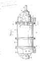
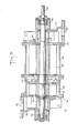
- a two-stage liquid ring pump 10 constructed in accordance with the principles of this invention includes first stage head member 12, first stage inlet port member 14, first stage housing member 16 (including first stage outlet port member 18), second stage housing member 24 (including interstage head portion 20 and second stage inlet port member 22), second stage outlet port member 26, and second stage head member 28.
- Shaft 30 is rotatably mounted in the foregoing members by means of bearing assemblies 32 and 34 adjacent respective opposite axial ends of the pump.
- First stage rotor 40 is fixedly mounted on shaft 30 inside first stage housing member 16 between first stage inlet port member 14 and first stage outlet port member 18.
- Second stage rotor 42 is fixedly mounted on shaft 30 between second stage inlet port member 22 and second stage outlet port member 26. Rotors 40 and 42 rotate (with shaft 30) in the direction indicated by arrow 44 in FIG. 2.
- first stage housing 16 is partly filled with pumping liquid (usually water) and is somewhat eccentric relative to rotor 40. As rotor 40 rotates, it engages the pumping liquid and forms it into a recirculating eccentric ring inside housing 16. On the side of the pump including inlet port 52 the inner surface of this ring is receding from shaft 30 in the direction of rotor rotation. This causes gas to be drawn into the spaces between the blades of rotor 40 in this region of the pump.
- pumping liquid usually water
- the inner surface of the liquid ring is converging toward shaft 30 in the direction of rotor rotation. Accordingly, on this side of the pump the gas is compressed between the blades of rotor 40 and the partially compressed gas is discharged from the first stage via first stage discharge port 54 in port member 18.
- first stage of pump 10 is relatively long (i.e., the length of rotor 40 is at least about one-half its diameter)
- not all of the partially compressed gas may be able to exit via discharge port 54.
- some of the partially compressed gas may be trapped near first stage inlet port member 14.
- residual gas outlet port 60 is provided in port member 14 at a location after discharge port 54 but before inlet port 52 in the direction of rotor rotation to allow this partially compressed gas to exit from the first stage of the pump.
- Outlet port 60 communicates with residual gas conduit 62 in head member 12.
- Residual gas conduit 62 conveys the gas from outlet port 60 to residual gas inlet port 64, which is also provided in port member 14, but at a location after inlet port 52 and before discharge port 54 in the direction of rotor rotation. Accordingly, the gas from conduit 62 re-enters the first stage at a point where it does not interfere with the intake of new gas via inlet port 52 and where at least a portion of its compression is preserved. Conduit 62 keeps the gas flowing therethorough separate from both the intake gas in conduit 50 and the conventional make-up pumping liquid flow in conduit 66. Conduit 62 is formed as a channel in the surface of head member 14 which is otherwise in contact with port member 14. Conduit 62 extends part way around the pump, conveying the gas flowing therein around one side of shaft 30, as well as around make-up pumping liquid conduit 66.
- Elements 60, 62, and 64 allow the first stage of pump 10 to be made much longer (in relation to its diameter) than it could otherwise be made without resorting to some of the other, relatively disadvantageous expedients mentioned above.
- elements 60, 62, and 64 allow the length of rotor 40 to be made considerably longer than one-half its diameter.
- the length of rotor 40 can be from about 5 to about 1.2 or more times its diameter, preferably from about .5 to about 1.0 times its diameter.
- the partially compressed gas from discharge port 54 flows through interstage passage 70 and enters the second stage of the pump via second stage inlet port 72 in port member 22.
- the second stage operates in a manner similar to the first stage to further compress the gas and to discharge the fully compressed gas via second stage discharge port 74 in port member 26.
- the fully compressed gas exits the pump via conduit 76.
- second stage discharge port 74 can be provided with a partial check valve arrangement (not shown but of a well-known type such as one or more ball or flapper valves) to prevent over-compression in the second stage when the pump is being started.
- head member 28 can be identical to head member 12.
- conduit 62 The structural counterpart of conduit 62 would then be present in head member 28 but would not be used.
- the interstage portion of shaft 30 can be surrounded by an annular collar 90 extending axially between first stage outlet port member 18 and second stage inlet port member 22.
- the annular clearance between shaft 30 and collar 90 can be filled with high pressure pumping liquid preferably withdrawn from a high pressure portion of the second stage liquid ring and supplied to the annular clearance by schematically represented conduit 92.
Landscapes
- Engineering & Computer Science (AREA)
- Mechanical Engineering (AREA)
- General Engineering & Computer Science (AREA)
- Applications Or Details Of Rotary Compressors (AREA)
- Structures Of Non-Positive Displacement Pumps (AREA)
- Compressors, Vaccum Pumps And Other Relevant Systems (AREA)
Applications Claiming Priority (2)
| Application Number | Priority Date | Filing Date | Title |
|---|---|---|---|
| US141687A | 1987-01-08 | 1987-01-08 | |
| US1416 | 1987-01-08 |
Publications (3)
| Publication Number | Publication Date |
|---|---|
| EP0274272A2 true EP0274272A2 (de) | 1988-07-13 |
| EP0274272A3 EP0274272A3 (en) | 1989-02-01 |
| EP0274272B1 EP0274272B1 (de) | 1991-12-04 |
Family
ID=21695919
Family Applications (1)
| Application Number | Title | Priority Date | Filing Date |
|---|---|---|---|
| EP87311377A Expired - Lifetime EP0274272B1 (de) | 1987-01-08 | 1987-12-23 | Zweistufige Flüssigkeitsringpumpe |
Country Status (10)
| Country | Link |
|---|---|
| US (1) | US4795315A (de) |
| EP (1) | EP0274272B1 (de) |
| JP (1) | JPS63192980A (de) |
| KR (1) | KR960014088B1 (de) |
| AU (1) | AU601540B2 (de) |
| BR (1) | BR8800037A (de) |
| CA (1) | CA1305690C (de) |
| DE (1) | DE3775023D1 (de) |
| FI (1) | FI880032A7 (de) |
| ZA (1) | ZA879710B (de) |
Cited By (1)
| Publication number | Priority date | Publication date | Assignee | Title |
|---|---|---|---|---|
| US5122035A (en) * | 1988-06-08 | 1992-06-16 | Pentamo Oy | Liquid ring compressor |
Families Citing this family (12)
| Publication number | Priority date | Publication date | Assignee | Title |
|---|---|---|---|---|
| US5186219A (en) * | 1984-11-08 | 1993-02-16 | Earth Resources Consultants, Inc. | Cylinder rupture vessel |
| US5383499A (en) * | 1992-05-04 | 1995-01-24 | Earth Resources Corporation | System for removal of unknown, corrossive, or potentially hazardous gases from a gas container |
| US5474114A (en) | 1993-05-28 | 1995-12-12 | Earth Resources Corporation | Apparatus and method for controlled penetration of compressed fluid cylinders |
| US5580222A (en) * | 1993-12-03 | 1996-12-03 | Tuthill Corporation | Liquid ring vacuum pump and method of assembly |
| US5900216A (en) * | 1996-06-19 | 1999-05-04 | Earth Resources Corporation | Venturi reactor and scrubber with suckback prevention |
| US6164344A (en) | 1997-07-28 | 2000-12-26 | Earth Resources Corporation | Sealable recovery vessel system and method for accessing valved containers |
| US5868174A (en) * | 1997-07-28 | 1999-02-09 | Earth Resources Corporation | System for accessing and extracting contents from a container within a sealable recovery vessel |
| DE19758340A1 (de) * | 1997-12-22 | 1999-07-08 | Gardner Denver Wittig Gmbh | Mehrflutige Flüssigkeitsringpumpe |
| US5993170A (en) * | 1998-04-09 | 1999-11-30 | Applied Materials, Inc. | Apparatus and method for compressing high purity gas |
| US8573896B2 (en) * | 2007-10-17 | 2013-11-05 | Remco International, Inc. | Method of dynamic energy-saving superconductive transporting of medium flow |
| US9689387B2 (en) * | 2012-10-30 | 2017-06-27 | Gardner Denver Nash, Llc | Port plate of a flat sided liquid ring pump having a gas scavenge passage therein |
| GB2559330A (en) * | 2017-01-26 | 2018-08-08 | Ecofuel Tech Ltd | Reaction pump, system and method for thermal conversion hydrocarbons |
Family Cites Families (24)
| Publication number | Priority date | Publication date | Assignee | Title |
|---|---|---|---|---|
| DE258854C (de) * | ||||
| DE258483C (de) * | ||||
| GB191228906A (en) * | 1912-12-16 | 1913-05-01 | Siemens Brothers Dynamo Works | Improvements in or relating to Rotary Pumps. |
| US1322363A (en) * | 1917-08-07 | 1919-11-18 | Siemens Schuckertwerke Gmbh | Rotary blower or pump. |
| US1656728A (en) * | 1924-01-25 | 1928-01-17 | Safety Car Heating & Lighting | Construction for compressors and the like |
| US2136527A (en) * | 1935-12-21 | 1938-11-15 | Stelzer Berteli | Refrigerating and air-conditioning system in conjunction with internal combustion engines |
| US2195174A (en) * | 1935-12-30 | 1940-03-26 | Irving C Jennings | Pump |
| FR927115A (fr) * | 1945-06-28 | 1947-10-21 | Const Burckhardt Sa Des Atel | Pompe à vide à anneau liquide |
| GB691425A (en) * | 1950-06-03 | 1953-05-13 | Otto Siemen | Improvements in or relating to two stage liquid-ring air-pumps |
| DE823170C (de) * | 1950-06-11 | 1951-12-03 | Johannes Hinsch | Zweistufige Fluessigkeitsring-Luftpumpe |
| GB703533A (en) * | 1951-07-09 | 1954-02-03 | Otto Siemen | Two-stage liquid ring pump |
| GB710611A (en) * | 1951-07-09 | 1954-06-16 | Otto Siemen | Multi-stage liquid ring air pump |
| DE1047981B (de) * | 1956-01-19 | 1958-12-31 | Siemens Ag | Mehrstufige Fluessigkeitsringgaspumpe mit Zwischengehaeuse |
| AT198418B (de) * | 1956-05-02 | 1958-07-10 | Otto Siemen | Mehrstufige Flüssigkeitsring-Vakuumpumpe |
| GB858422A (en) * | 1956-05-02 | 1961-01-11 | Otto Siemen | Multi-stage liquid-ring gas-pump |
| DE1054652B (de) * | 1956-05-02 | 1959-04-09 | Johannes Hinsch | Mehrstufige Fluessigkeitsring-Vakuumpumpe |
| JPS5234411A (en) * | 1975-09-11 | 1977-03-16 | Kazuhito Nasu | Two stepped water seal pump |
| US4132504A (en) * | 1976-04-07 | 1979-01-02 | General Signal Corporation | Liquid ring pump |
| US4334830A (en) * | 1980-03-24 | 1982-06-15 | The Nash Engineering Company | Two-stage liquid ring pump with improved intrastage and interstage sealing means |
| SU914809A1 (ru) * | 1980-06-26 | 1982-03-23 | Lev T Karaganov | Жидкостнокольцевая машина 1 |
| DE3568823D1 (en) * | 1984-05-14 | 1989-04-20 | Prescant Pty Ltd | Water ring vacuum pump |
| DE3427628A1 (de) * | 1984-07-26 | 1986-01-30 | Sihi Gmbh & Co Kg, 2210 Itzehoe | Fluessigkeitsring-verdichter |
| SU1239405A1 (ru) * | 1984-12-28 | 1986-06-23 | Предприятие П/Я А-3605 | Жидкостно-кольцева машина |
| US4679987A (en) * | 1986-05-19 | 1987-07-14 | The Nash Engineering Company | Self-priming liquid ring pump methods and apparatus |
-
1987
- 1987-08-07 KR KR1019870008665A patent/KR960014088B1/ko not_active Expired - Fee Related
- 1987-12-23 EP EP87311377A patent/EP0274272B1/de not_active Expired - Lifetime
- 1987-12-23 DE DE8787311377T patent/DE3775023D1/de not_active Expired - Lifetime
- 1987-12-28 ZA ZA879710A patent/ZA879710B/xx unknown
-
1988
- 1988-01-05 AU AU10056/88A patent/AU601540B2/en not_active Ceased
- 1988-01-06 JP JP63000438A patent/JPS63192980A/ja active Pending
- 1988-01-06 FI FI880032A patent/FI880032A7/fi not_active Application Discontinuation
- 1988-01-07 BR BR8800037A patent/BR8800037A/pt not_active IP Right Cessation
- 1988-01-08 CA CA000556144A patent/CA1305690C/en not_active Expired - Lifetime
- 1988-03-24 US US07/175,666 patent/US4795315A/en not_active Expired - Fee Related
Cited By (1)
| Publication number | Priority date | Publication date | Assignee | Title |
|---|---|---|---|---|
| US5122035A (en) * | 1988-06-08 | 1992-06-16 | Pentamo Oy | Liquid ring compressor |
Also Published As
| Publication number | Publication date |
|---|---|
| EP0274272A3 (en) | 1989-02-01 |
| DE3775023D1 (de) | 1992-01-16 |
| AU601540B2 (en) | 1990-09-13 |
| JPS63192980A (ja) | 1988-08-10 |
| FI880032A0 (fi) | 1988-01-06 |
| KR880009213A (ko) | 1988-09-14 |
| BR8800037A (pt) | 1988-08-02 |
| FI880032A7 (fi) | 1988-07-09 |
| ZA879710B (en) | 1988-06-23 |
| EP0274272B1 (de) | 1991-12-04 |
| KR960014088B1 (ko) | 1996-10-12 |
| US4795315A (en) | 1989-01-03 |
| CA1305690C (en) | 1992-07-28 |
| AU1005688A (en) | 1988-07-14 |
Similar Documents
| Publication | Publication Date | Title |
|---|---|---|
| US4795315A (en) | Two-stage liquid ring pump | |
| US4650405A (en) | Scroll pump with axially spaced pumping chambers in series | |
| CA1233148A (en) | Liquid ring pump with conical or cylindrical port member | |
| EP0155419B1 (de) | Schallminderungseinrichtung für Flüssigkeitsring-Pumpen mit konisch angeordneten Durchlässen | |
| US4614232A (en) | Device for delivering flowable material | |
| US4355951A (en) | Full admission pitot pump | |
| US4668160A (en) | Vacuum pump | |
| EP0708889B1 (de) | Schraubenverdichter | |
| EP0578890A1 (de) | Spiralverdichter mit Auslassdiffusor | |
| US4545730A (en) | Liquid ring vacuum pump for gaseous media | |
| JP2004518905A (ja) | 直噴式内燃機関の燃料システムのための高圧燃料ポンプ、燃料システム並びに内燃機関 | |
| US6969242B2 (en) | Compressor | |
| US6200116B1 (en) | Vacuum pumps | |
| EP0420886A1 (de) | Verdichter mit einem flüssigkeitsring. | |
| US4850808A (en) | Liquid ring pump having port member with internal passageways for handling carry-over gas | |
| US3084851A (en) | Rotary machine | |
| KR930010816B1 (ko) | 쓰러스트손실을 보상시킨 나선형 날개깃 방식의 압축기 | |
| CA2226799C (en) | Two-stage liquid ring pumps | |
| CN214788011U (zh) | 一种蜗壳导叶式多级泵 | |
| US3351272A (en) | Vacuum pump | |
| US4462751A (en) | Centrifugal pump improvement | |
| CN1018943B (zh) | 单吸对置式多级离心式潜水泵 | |
| CA1188153A (en) | Full admission pitot pump | |
| SU754113A1 (ru) | Многоступенчатый центробежный насос | |
| CN212563688U (zh) | 一种双吸多级潜水电泵 |
Legal Events
| Date | Code | Title | Description |
|---|---|---|---|
| PUAI | Public reference made under article 153(3) epc to a published international application that has entered the european phase |
Free format text: ORIGINAL CODE: 0009012 |
|
| AK | Designated contracting states |
Kind code of ref document: A2 Designated state(s): DE GB SE |
|
| PUAL | Search report despatched |
Free format text: ORIGINAL CODE: 0009013 |
|
| AK | Designated contracting states |
Kind code of ref document: A3 Designated state(s): DE GB SE |
|
| 17P | Request for examination filed |
Effective date: 19890728 |
|
| 17Q | First examination report despatched |
Effective date: 19900517 |
|
| GRAA | (expected) grant |
Free format text: ORIGINAL CODE: 0009210 |
|
| AK | Designated contracting states |
Kind code of ref document: B1 Designated state(s): DE GB SE |
|
| REF | Corresponds to: |
Ref document number: 3775023 Country of ref document: DE Date of ref document: 19920116 |
|
| PLBI | Opposition filed |
Free format text: ORIGINAL CODE: 0009260 |
|
| 26 | Opposition filed |
Opponent name: SIEMENS AG GR PA 2 ERL S Effective date: 19920821 |
|
| GBPC | Gb: european patent ceased through non-payment of renewal fee | ||
| REG | Reference to a national code |
Ref country code: GB Ref legal event code: 728C |
|
| REG | Reference to a national code |
Ref country code: GB Ref legal event code: 728A |
|
| EUG | Se: european patent has lapsed |
Ref document number: 87311377.3 Effective date: 19920904 |
|
| PLBN | Opposition rejected |
Free format text: ORIGINAL CODE: 0009273 |
|
| STAA | Information on the status of an ep patent application or granted ep patent |
Free format text: STATUS: OPPOSITION REJECTED |
|
| 27O | Opposition rejected |
Effective date: 19941209 |
|
| PGFP | Annual fee paid to national office [announced via postgrant information from national office to epo] |
Ref country code: GB Payment date: 19971121 Year of fee payment: 11 |
|
| PGFP | Annual fee paid to national office [announced via postgrant information from national office to epo] |
Ref country code: DE Payment date: 19971124 Year of fee payment: 11 |
|
| PGFP | Annual fee paid to national office [announced via postgrant information from national office to epo] |
Ref country code: SE Payment date: 19971217 Year of fee payment: 11 |
|
| PG25 | Lapsed in a contracting state [announced via postgrant information from national office to epo] |
Ref country code: GB Free format text: LAPSE BECAUSE OF NON-PAYMENT OF DUE FEES Effective date: 19981223 |
|
| PG25 | Lapsed in a contracting state [announced via postgrant information from national office to epo] |
Ref country code: SE Free format text: THE PATENT HAS BEEN ANNULLED BY A DECISION OF A NATIONAL AUTHORITY Effective date: 19981230 |
|
| GBPC | Gb: european patent ceased through non-payment of renewal fee |
Effective date: 19981223 |
|
| PG25 | Lapsed in a contracting state [announced via postgrant information from national office to epo] |
Ref country code: DE Free format text: LAPSE BECAUSE OF NON-PAYMENT OF DUE FEES Effective date: 19991001 |