EP0272926A2 - Electrode de condensateur en aluminium pour condensateurs électrolytiques et son procédé de fabrication - Google Patents
Electrode de condensateur en aluminium pour condensateurs électrolytiques et son procédé de fabrication Download PDFInfo
- Publication number
- EP0272926A2 EP0272926A2 EP87311346A EP87311346A EP0272926A2 EP 0272926 A2 EP0272926 A2 EP 0272926A2 EP 87311346 A EP87311346 A EP 87311346A EP 87311346 A EP87311346 A EP 87311346A EP 0272926 A2 EP0272926 A2 EP 0272926A2
- Authority
- EP
- European Patent Office
- Prior art keywords
- titanium
- aluminum
- layer
- projections
- producing
- Prior art date
- Legal status (The legal status is an assumption and is not a legal conclusion. Google has not performed a legal analysis and makes no representation as to the accuracy of the status listed.)
- Granted
Links
- 229910052782 aluminium Inorganic materials 0.000 title claims abstract description 71
- XAGFODPZIPBFFR-UHFFFAOYSA-N aluminium Chemical compound [Al] XAGFODPZIPBFFR-UHFFFAOYSA-N 0.000 title claims abstract description 71
- 239000003990 capacitor Substances 0.000 title claims abstract description 53
- 238000000034 method Methods 0.000 title claims description 35
- RTAQQCXQSZGOHL-UHFFFAOYSA-N Titanium Chemical compound [Ti] RTAQQCXQSZGOHL-UHFFFAOYSA-N 0.000 claims abstract description 89
- 239000010936 titanium Substances 0.000 claims abstract description 89
- 229910052719 titanium Inorganic materials 0.000 claims abstract description 89
- 239000002245 particle Substances 0.000 claims abstract description 28
- 239000011148 porous material Substances 0.000 claims abstract description 24
- 238000007747 plating Methods 0.000 claims description 20
- VEXZGXHMUGYJMC-UHFFFAOYSA-N Hydrochloric acid Chemical compound Cl VEXZGXHMUGYJMC-UHFFFAOYSA-N 0.000 claims description 13
- 238000005530 etching Methods 0.000 claims description 13
- GRYLNZFGIOXLOG-UHFFFAOYSA-N Nitric acid Chemical compound O[N+]([O-])=O GRYLNZFGIOXLOG-UHFFFAOYSA-N 0.000 claims description 11
- 229910017604 nitric acid Inorganic materials 0.000 claims description 11
- NBIIXXVUZAFLBC-UHFFFAOYSA-N Phosphoric acid Chemical compound OP(O)(O)=O NBIIXXVUZAFLBC-UHFFFAOYSA-N 0.000 claims description 9
- 235000011007 phosphoric acid Nutrition 0.000 claims description 9
- QAOWNCQODCNURD-UHFFFAOYSA-N Sulfuric acid Chemical compound OS(O)(=O)=O QAOWNCQODCNURD-UHFFFAOYSA-N 0.000 claims description 8
- 235000011149 sulphuric acid Nutrition 0.000 claims description 8
- 239000003792 electrolyte Substances 0.000 claims description 7
- 238000000866 electrolytic etching Methods 0.000 claims description 4
- 239000011261 inert gas Substances 0.000 claims description 4
- 238000003486 chemical etching Methods 0.000 claims description 3
- 238000001704 evaporation Methods 0.000 claims description 2
- 239000010408 film Substances 0.000 description 44
- 239000011888 foil Substances 0.000 description 23
- 230000001965 increasing effect Effects 0.000 description 13
- 239000000203 mixture Substances 0.000 description 8
- 239000000243 solution Substances 0.000 description 8
- 238000004519 manufacturing process Methods 0.000 description 6
- XKRFYHLGVUSROY-UHFFFAOYSA-N Argon Chemical compound [Ar] XKRFYHLGVUSROY-UHFFFAOYSA-N 0.000 description 4
- 239000000126 substance Substances 0.000 description 4
- XEEYBQQBJWHFJM-UHFFFAOYSA-N Iron Chemical compound [Fe] XEEYBQQBJWHFJM-UHFFFAOYSA-N 0.000 description 2
- VSCWAEJMTAWNJL-UHFFFAOYSA-K aluminium trichloride Chemical compound Cl[Al](Cl)Cl VSCWAEJMTAWNJL-UHFFFAOYSA-K 0.000 description 2
- 229910052786 argon Inorganic materials 0.000 description 2
- NGPGDYLVALNKEG-UHFFFAOYSA-N azanium;azane;2,3,4-trihydroxy-4-oxobutanoate Chemical compound [NH4+].[NH4+].[O-]C(=O)C(O)C(O)C([O-])=O NGPGDYLVALNKEG-UHFFFAOYSA-N 0.000 description 2
- 230000015572 biosynthetic process Effects 0.000 description 2
- 238000001816 cooling Methods 0.000 description 2
- 230000000694 effects Effects 0.000 description 2
- 230000002708 enhancing effect Effects 0.000 description 2
- 238000002474 experimental method Methods 0.000 description 2
- 239000012530 fluid Substances 0.000 description 2
- 239000000463 material Substances 0.000 description 2
- 230000005855 radiation Effects 0.000 description 2
- 239000012798 spherical particle Substances 0.000 description 2
- WYXIGTJNYDDFFH-UHFFFAOYSA-Q triazanium;borate Chemical compound [NH4+].[NH4+].[NH4+].[O-]B([O-])[O-] WYXIGTJNYDDFFH-UHFFFAOYSA-Q 0.000 description 2
- RYGMFSIKBFXOCR-UHFFFAOYSA-N Copper Chemical compound [Cu] RYGMFSIKBFXOCR-UHFFFAOYSA-N 0.000 description 1
- FEWJPZIEWOKRBE-JCYAYHJZSA-N Dextrotartaric acid Chemical compound OC(=O)[C@H](O)[C@@H](O)C(O)=O FEWJPZIEWOKRBE-JCYAYHJZSA-N 0.000 description 1
- MUBZPKHOEPUJKR-UHFFFAOYSA-N Oxalic acid Chemical compound OC(=O)C(O)=O MUBZPKHOEPUJKR-UHFFFAOYSA-N 0.000 description 1
- FEWJPZIEWOKRBE-UHFFFAOYSA-N Tartaric acid Natural products [H+].[H+].[O-]C(=O)C(O)C(O)C([O-])=O FEWJPZIEWOKRBE-UHFFFAOYSA-N 0.000 description 1
- 239000000956 alloy Substances 0.000 description 1
- 229910045601 alloy Inorganic materials 0.000 description 1
- 239000007864 aqueous solution Substances 0.000 description 1
- KGBXLFKZBHKPEV-UHFFFAOYSA-N boric acid Chemical compound OB(O)O KGBXLFKZBHKPEV-UHFFFAOYSA-N 0.000 description 1
- 239000004327 boric acid Substances 0.000 description 1
- 229910052802 copper Inorganic materials 0.000 description 1
- 239000010949 copper Substances 0.000 description 1
- 230000003247 decreasing effect Effects 0.000 description 1
- 229910052742 iron Inorganic materials 0.000 description 1
- 229910052751 metal Inorganic materials 0.000 description 1
- 239000002184 metal Substances 0.000 description 1
- 150000002739 metals Chemical class 0.000 description 1
- 230000002035 prolonged effect Effects 0.000 description 1
- 235000002906 tartaric acid Nutrition 0.000 description 1
- 239000011975 tartaric acid Substances 0.000 description 1
- 239000010409 thin film Substances 0.000 description 1
- 239000002699 waste material Substances 0.000 description 1
- 238000004804 winding Methods 0.000 description 1
Images


Classifications
-
- H—ELECTRICITY
- H01—ELECTRIC ELEMENTS
- H01G—CAPACITORS; CAPACITORS, RECTIFIERS, DETECTORS, SWITCHING DEVICES, LIGHT-SENSITIVE OR TEMPERATURE-SENSITIVE DEVICES OF THE ELECTROLYTIC TYPE
- H01G9/00—Electrolytic capacitors, rectifiers, detectors, switching devices, light-sensitive or temperature-sensitive devices; Processes of their manufacture
- H01G9/004—Details
- H01G9/04—Electrodes or formation of dielectric layers thereon
- H01G9/042—Electrodes or formation of dielectric layers thereon characterised by the material
- H01G9/045—Electrodes or formation of dielectric layers thereon characterised by the material based on aluminium
-
- H—ELECTRICITY
- H01—ELECTRIC ELEMENTS
- H01G—CAPACITORS; CAPACITORS, RECTIFIERS, DETECTORS, SWITCHING DEVICES, LIGHT-SENSITIVE OR TEMPERATURE-SENSITIVE DEVICES OF THE ELECTROLYTIC TYPE
- H01G9/00—Electrolytic capacitors, rectifiers, detectors, switching devices, light-sensitive or temperature-sensitive devices; Processes of their manufacture
- H01G9/004—Details
- H01G9/04—Electrodes or formation of dielectric layers thereon
- H01G9/048—Electrodes or formation of dielectric layers thereon characterised by their structure
Definitions
- the present invention relates to an aluminum capacitor plate for use in electrolytic capacitors and a process for producing the same. More particularly, the present invenion relates to an aluminum capacitor plate having an enhanced capacitance, and to a process for producing such capacitor plates, wherein the term "aluminum" includes pure aluminum and aluminum-based alloys.
- the electolytic capacitor will be referred to merely as capacitor.
- the present invention aims at solving the problems pointed out with respect to the known capacitor plates and the known process of producing the same, and has for its object to provide an aluminum capacitor plate having an enhanced capacitance, and a process for producing such capacitor plates.
- an aluminum capacitor plate for use in an electrolytic capacitor, which plate comprises: a layer of a sponge-like structure having a predetermined thickness, the layer including a plurality of projections extending inward and outward with respect thereto, the projections individually having heights of not higher than 1 ⁇ m on average; and a titanium film having accumulated titanium particles each including projections having heights of not higher than 1 ⁇ m, wherein the titanium particles are unevenly distributed in the film with a number of pores interposed therebetween.
- the layer of sponge-like structure can be produced by controlling the etching conditions, in which a mixture of HCl and one or more solutions selected from HNO3, H3PO4 and H2SO4 is used as an electrolyte.
- the titanium film is preferably produced by more than two steps of vapor-plating; if the film having 1 ⁇ m or more is produced by a single step the temperature of the aluminum plate is likely to rise by the influences of the latent heat generated when the titanium condenses into particles and of the radiation from the source of heat for evaporating titanium. While the vapor-plating is in process the aluminum plate is cooled in a cooling vessel but nevertheless its temperature normally reaches 300°C or more. Because of the high temperature of the aluminum plate the titanium particles tend to become fluid, and make a flat film. This negates the aim of producing a film having rugged surfaces and increasing the surface area of the aluminum plate.
- a first step of vapor-plating is applied to the aluminum plate while it is rolled up, and a second step is applied to it while being unrolled. In this way a third step, a fourth step and so on are applied until a desired number of layers are produced.
- the capacitor plate of the invention has a substratum 1 of aluminum plate (foil) having an etched layer 2 of sponge-like structure extending to a predetermined thickness (t).
- the songe-like layer 2 is provided with a vapor-plated titanium film 4, whose surface is made uneven by etching.
- the substratum 1 is made of a material adapted for producing the sponge-like layer 2 therein.
- Preferably pure aluminum or at least A1100 grade aluminum is used but the material is not limited thereto.
- the aluminum plate (foil) is preferably 15 to 70 ⁇ m thick.
- the sponge-like layer 2 contains a number of pores, among which the pores 2a communicate with one another, while the pores 2b are closed for each other.
- the pores 2a, 2b are made of pits of 0.01 to 5 ⁇ m on average, wherein the pores 2a are solely or jointly present, but such larger size of pits as 1.2 to 40 ⁇ m may be present from place to place.
- the sponge-like layer 2 is preferably made rugged with hills having heights of 0.01 to 5 ⁇ m.
- the volumetric percentage of the pores 2a and 2b is 30 to 80% for the whole sponge-like layer 2.
- the sponge-like layer 2 may be produced on one of the surfaces of the substratum 1 or on both surfaces thereof.
- the thickness (t) of the sponge-like layer 2 is preferably in the range of 2.5 to 25 ⁇ m, that is, when it is provided on both surfaces the total thickness may be in the range of 5 to 50 ⁇ m, provided that it is within 30 to 85% of the total thickness of the substratum 1. If the sponge-like layer 2 is less than 2.5 ⁇ m thick, it is likely that the titanium film fails to extend fully thereon, and that the surface area of the capacitor plate is not increased sufficiently to enhance the capacitance thereof. If the thickness of the layer 2 exceeds 25 ⁇ m the substratum 1 relatively becomes thin, thereby making the plate fragile. Most preferably the thickness of the layer 2 is in the range of 5 to 20 ⁇ m on either side of the surfaces.
- the sponge-like layer 2 is also provided with small projections 3 of 1 ⁇ m or less high, extending toward the pores 2a and 2b. Because of the underlying projections 3 the overlying titanium film 4 is made rugged on its surface, thereby increasing the surface area thereof. However if the height (h) of the projections 3 are higher than 1 ⁇ m the surface area of the titanium film do not increase so much. The optimum height is in the range of 0.1 to 0.5 ⁇ m.
- the sponge-like layer 2 including the projections 3 are produced by etching.
- the etching process is carried out under selected conditions; for example, the compositions of the electrolyte are selected from a particular group, the temperature of the electrolyte is variously adjusted, and the time of operation is prolonged or shortened.
- the compositions of the electrolyte are selected from a particular group, the temperature of the electrolyte is variously adjusted, and the time of operation is prolonged or shortened.
- the etching can be electro-chemical or chemical.
- the electrolyte can be selected from a mixture of HCl, HNO3 and H3PO4; a mixture of HCl, HNO3, H3PO4 and H2SO4; a mixture of HCl, HNO3 H3PO4 and H2SO4; a mixture of HCl, HNO3, H3PO4 H2SO4 and AlCl3; a mixture of HCl and H2C2O4; and a HCl solution.
- the temperature is preferably 30 to 85°C, and the etching is normally continued for 1 to 10 minutes but it depends upon the other etching conditions.
- an alternating currect is preferably used but of course a direct current can be used.
- the current density is adjusted to 3 to 30A/dm2.
- the etching can be finished with a single dose of titanium, two doses, three does or more, depending upon the desired thickness of the titanium film.
- the reason why the substance of the outer film is limited to titanium is its superior durability as compared with other electrically conductive metals, such as iron and copper.
- the durability of the outer film leads to the long life and reliability of the capacitor.
- the titanium particles are generally shaped as shown in Figs. 3 to 5; in Fig. 3 they are scaled-shape, and in Figs. 4 and 5 they are shperical.
- the titanium film 4 consists essentially of the accumulating particles.
- Each scale-shaped particle 5 includes small projections 6 having an average height (H) of 1 ⁇ m or less, thereby making the surface of the film rugged. However if the height (H) exceeds 1 ⁇ m the surface area is not sufficiently increased to enahnce the capacitance of the plate.
- the optimum height (H) is in the range of 0.1 to 0.6 ⁇ m.
- the average diameter (r) including the projections 6 is preferably in the range of 0.5 to 3 ⁇ m.
- the titanium film 4 also includes valleys 7 having depths of 20 ⁇ m or less on average.
- the valleys 7 and the projections 6 impart a combined ruggedness to the surface of the titanium film, thereby increasing the surface area thereof.
- the increased surface area of the outer film 4 leads to the enhanced capacitance of the capacitor plate.
- the entire inside walls of the valleys 7 are preferably covered with the titanium film but the aluminum of the substratum 1 may be exposed therein.
- the titanium particles it is not necessary for the titanium particles to take the same shape in one substratum 1, but it is possible for a mixture to be present therein.
- the conditions for carrying out the titanium vapor-plating can be variously decided but it is important that the surfacial temperature of the aluminum substratum 1 is kept at not higher than 300°C. If it exceeds 300°C the titanium particles 5 accumulating on the surface of the substratum 1 are likely to become molten and fluid, thereby producing a flat surface. As a result the projections 6 are not produced. If the surfacial temperature is too low the titanium particles 5 are difficult to stick to the substratum 1. The optimum range is about 50 to 200°C.
- the vapor-plating process is preferably carried out in an atmosphere of an inert gas at a pressure of 1 X 10 ⁇ 4 to 5 X 10 ⁇ 3 Torr.
- a first dose of titanium is plated on the surface of the substratum 1 by a first step of vaporing, and as shown in Fig. 6 the first layer 4a is produced. As the amount of titanium is small the temperature of the substratum 1 does not rise very high. After the plated substratum 1 is allowed to cool, a second dose is applied to the first layer 4a to produce a second layer 4b. Subsequently a third dose, a fourth dose and so on are consecutively applied so as to produce a third layer 4c, a fourth layer 4d and so on. In this way the substratum 1 is kept at a relatively low temperature throughout the process.
- the intermittent application of the titanium vapor is carried out by the use of the device shown in Fig. 7.
- the aluminum platee (foil) is previously rolled up into a first roll 8 within a Bell-jar (not shown).
- the plate is unwound from the roll 8, and rolled up into a secondd roll 9.
- the plate is kept in contact with the undersurface of a colling roller 11, and receives titanium vapor caused by an electronic beam generator 10.
- the plate having the first layer 4a is rolled up into the roll 9.
- the plate is unwound from the roll 9, and returned toward the first roll 8 during which it is subjected to the same process, thereby having the second titanium layer 4b.
- the same procedure is repeated until the desired number of layers are produced.
- the reference numerals 12 and 13 denote guide rollers and a shield, respectively.
- the total thickness of the titanium layers is preferably in the range of 0.1 to 3.0 ⁇ m (it amounts to 0.045 to 1.35 mg/cm2 in terms of quantity). If the total thickness is less than 0.1 ⁇ m, the surface of the film is likely to fail to have a rugged surface but to become flat, thereby leading to the decreased capacitance. If it exceeds 3 ⁇ m no increased effects result only to lead to the waste of titanium.
- the number of the titanium layers is preferably in the range of 2 to 10, which means that the preferred doses of titanium are 2 to 10 times.
- the speed of the vapor-plating is determined depending upon the desired thickness of the titanium film and the number of doses. Preferably the speed is adjusted to 100 to 5000 ⁇ /sec (4.5 x 10 ⁇ 3 to 0.225mg/cm2 sec in terms of quantity). If the speed exceeds 5000 ⁇ /sec the ambient pressure fails to affect the process favorably. The increased capacitance cannot be expected. If the speed slows down up to less than 100 ⁇ /sec the working efficiency is reduced, thereby resulting in the increased production cost.
- the process is carried out in the atmosphere of an inert gas, such as Ar, wherein the pressure is preferably adjusted to 5 x 10 ⁇ 5 to 5 x 10 ⁇ 3 Torr.
- the inert gas atmosphere is conducive to the formation of a rough surface.
- the surfacial particles are likely to become too small, thereby failing to increase the capacitance of the capacitor plate.
- the ambient pressure exceeds 5 x 10 ⁇ 3 Torr the titanium particles become difficult not only to evaporate but also to stick to the aluminum substratum 1.
- the experiments have revealed that the optimum pressure is 1 x 10 ⁇ 3 Torr, which is particularly adapted for the mass production.
- the distance over which the titanium particles fly is preferably 150 to 400mm. If it exceeds 400mm the titanium is difficult to stick to the aluminum substratum 1; in other words, a large quantity of titanium vapor is wasted without forming the film.
- the aluminum plate covered with the titanium film can be used as a nagative electrode for electrolytic capacitors without having any further process but if it is treated in a solution of boric acid, ammonium borate , tartaric acid, or ammonium tartrate or an aqueous solution thereof so as to cover it with an oxidized film, it can be used as a positive electrode.
- the capaccitor plate is provided with a sponge-like rough surface, and then covered with a titanium film so as to produce the doubled rugged surfaces.
- the titanium film includes as small projections as 1 ⁇ m or less in height with pores interlocated therebetween.
- An aluminum foil of 50 ⁇ m in thickness and of 99.8% purity was immersed in a solution, heated at 50°C, containing 200ml/l of HCl, 6ml/l of HNO3, 3ml/l of H3PO4 and 1ml/l of H2SO4, and subjected to an a.c. electrolytic etching at a current density of 20A/dm2 for two minutes.
- the foil had a spong-like layer of 16 ⁇ m at maximum on one side, which had pores each being made up of one or more pits of averagely 0.06 to 1.9 ⁇ m in depth. Partly the pores gathered and grew as large as 1.2 to 25 ⁇ m deep.
- the aluminum substratum was present in the form of projections of averagely 0.06 to 2.5 ⁇ m in height.
- the volumetric ratio of all the pores to the layer was about 58%.
- the sponge-like layer had projections of averagely 0.5 ⁇ m in height on its surface.
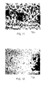
- Figs. 8 and 9 show microscopic views of the surface of the aluminum foil.
- the aluminum foil whose surfacial temperature was kept at 100°C was placed in an atmosphere of 1 x 10 ⁇ 3 Torr of argon. Then a titanium vapor-plating was conducted on the aluminum foil at a distance of 250mm, at a speed of 5 x 10 ⁇ 3mg/cm2 sec.
- the titanium film of averagely 0.5mg/cm2 was produced on the aluminum foil.
- the film was made up of virtually spherical titanium particles having lengths of 1.0 to 3.0 ⁇ m, and as shown in Fig. 14 each particle had small projections of averagely 0.3 ⁇ m in height.
- An aluminum foil of 40 ⁇ m in thickness and of 99.0% purity was immersed in a solution, heated at 50°C, containing 50ml/l of HCl, 2ml/l of HNO3 and 3ml/l of H3PO4, and subjected to an a.c. electrolytic etching at a current density of 30A/dm2 for two minutes.
- the foil had a spong-like layer of 16 ⁇ m at maximum on one side, which had pores each being made up of one or more pits of averagely 0.05 to 1.7 ⁇ m in depth. Partly the pores gathered to grow as large as 1.0 to 20 ⁇ m.
- the aluminum substratum was present in the form of bulges of averagely 0.06 to 2.5 ⁇ m in height.
- the volumetric ratio of all the pores to the layer was about 50%.
- the sponge-like layer had small projections of averagely 0.4 ⁇ m high on its surface.
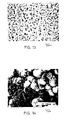
- Figs. 11 and 12 show microscopic views of the surface of the aluminum foil.
- the aluminum foil was heated to 50°C on its surface, and placed in an atmosphere of 1 x 10 ⁇ 4 Torr of argon. Then a titanium vapor-plating was conducted on the aluminum foil at a distance of 300mm, at a speed of 0.05/cm2 sec.
- the titanium film of averagely 0.5mg/cm2 was produced on the aluminum foil.
- the film was made up of scaled-shaped titanium particles and spherical particles having lengths of 1.0 to 3.0 ⁇ m, wherein the spherical particles stick to the apparent flat top portions of the scaled-shaped particles. Each particle was recognized to have projections of averagely 0.3 ⁇ m in height, as shown in Fig. 16.
- the titanium film had a number of pores of 20 ⁇ m or less in depth, some of which had the aluminum substratum exposed in their inside walls.
- the same aluminum foil as used in the Example (1) was immersed in a solution, heated at 95°C, containing 150ml/l of HCl, 10ml/l of HNO3 and 2ml/l of H2SO4, and subjected to a chemical etching for two minutes.
- the foil had a spong-like layer of 10 ⁇ m at maximum on one side, which had pores each being made up of one or more pits of averagely 0.08 to 2.5 ⁇ m in depth. Partly the pores gathered to grow as large as 1.0 to 30 ⁇ m.
- the aluminum substratum was present in the form of projections of averagely 0.08 to 3.0 ⁇ m in height.
- the volumetric ratio of all the pores to the layer was about 50%.
- the sponge-like layer had projections of averagely 0.5 ⁇ m in height on its surface.
- the aluminum foil was subjected to titanium vapor-plating under the same conditions as those for the Example (1).
- the aluminum foil had a titanium film of averagely 0.45mg/cm2.
- the same aluminum foil as used in the Example (1) was subjected to the same etching and titanium vapor-plating as those conducted in the Example (1).
- the processed aluminum foil was treated in a solution of ammonium tartrate film and the aluminum substratum exposed in the depths of the pores in the sponge-like layers were covered with an oxidized film of 120 ⁇ m or less in thickness.
Landscapes
- Engineering & Computer Science (AREA)
- Power Engineering (AREA)
- Microelectronics & Electronic Packaging (AREA)
- Chemical & Material Sciences (AREA)
- Materials Engineering (AREA)
- Electric Double-Layer Capacitors Or The Like (AREA)
- Fixed Capacitors And Capacitor Manufacturing Machines (AREA)
Applications Claiming Priority (4)
| Application Number | Priority Date | Filing Date | Title |
|---|---|---|---|
| JP310059/86 | 1986-12-24 | ||
| JP310058/86 | 1986-12-24 | ||
| JP61310059A JPH0748462B2 (ja) | 1986-12-24 | 1986-12-24 | 電解コンデンサ用アルミニウム電極材料の製造方法 |
| JP61310058A JPS63160322A (ja) | 1986-12-24 | 1986-12-24 | 電解コンデンサ用アルミニウム電極材料 |
Publications (3)
| Publication Number | Publication Date |
|---|---|
| EP0272926A2 true EP0272926A2 (fr) | 1988-06-29 |
| EP0272926A3 EP0272926A3 (en) | 1989-07-26 |
| EP0272926B1 EP0272926B1 (fr) | 1991-10-16 |
Family
ID=26566173
Family Applications (1)
| Application Number | Title | Priority Date | Filing Date |
|---|---|---|---|
| EP87311346A Expired - Lifetime EP0272926B1 (fr) | 1986-12-24 | 1987-12-23 | Electrode de condensateur en aluminium pour condensateurs électrolytiques et son procédé de fabrication |
Country Status (4)
| Country | Link |
|---|---|
| US (1) | US4763229A (fr) |
| EP (1) | EP0272926B1 (fr) |
| KR (1) | KR910005753B1 (fr) |
| DE (1) | DE3773870D1 (fr) |
Cited By (12)
| Publication number | Priority date | Publication date | Assignee | Title |
|---|---|---|---|---|
| EP0344316A1 (fr) * | 1987-07-30 | 1989-12-06 | Matsushita Electric Industrial Co., Ltd. | Procede de fabrication d'un condensateur electrolytique |
| DE4127743A1 (de) * | 1991-08-22 | 1993-03-04 | Fraunhofer Ges Forschung | Aluminiumfolie fuer elektrolytkondensatoren und verfahren zu deren herstellung |
| WO1997005633A1 (fr) * | 1995-08-01 | 1997-02-13 | Hans Hoffmann | Condensateur electrique, agencement de condensateurs electriques de ce type et leur procede de fabrication |
| WO1997037052A1 (fr) * | 1996-04-03 | 1997-10-09 | Zakrytoe Aktsionernoe Obschestvo 'skb 'istra' | Procede et dispositif de deposition de revetement poreux et feuille cathodique de condensateur electrolytique |
| EP0907191A2 (fr) * | 1997-10-03 | 1999-04-07 | Nippon Chemi-Con Corporation | Condensateur électrolytique |
| EP0940828A2 (fr) * | 1998-03-03 | 1999-09-08 | Acktar Ltd. | Procédé de production d'électrodes en feuille |
| EP0966008A2 (fr) * | 1998-04-20 | 1999-12-22 | Becromal S.p.A. | Méthode de fabrication d'une anode pour condensateurs électrolytiques, anode fabriquée de telle façon et condensateur contenant cette anode |
| WO2002097834A1 (fr) | 2001-05-31 | 2002-12-05 | Nippon Chemi-Con Corporation | Condensateur electrolytique et feuille d'electrode a utiliser dans un tel condensateur |
| EP1269547A1 (fr) * | 2000-02-03 | 2003-01-02 | Case Western Reserve University | Condensateurs haute puissance realises a partir de minces couches de poudre de metal ou de particules d'eponges metalliques |
| DE10219908A1 (de) * | 2002-05-03 | 2003-11-27 | Epcos Ag | Elektrode und ein Verfahren zu deren Herstellung |
| WO2005010903A1 (fr) * | 2003-07-15 | 2005-02-03 | Cabot Corporation | Anode de condensateur constituee de colonnes metalliques formees sur un substrat |
| EP2209130A2 (fr) * | 2007-11-12 | 2010-07-21 | Obschestvo S Ogranichennoi Otvetstvennostyu 'VOSTOK' | Anode multicouches |
Families Citing this family (22)
| Publication number | Priority date | Publication date | Assignee | Title |
|---|---|---|---|---|
| FR2688092B1 (fr) * | 1992-02-14 | 1994-04-15 | Traitement Metaux Alliages Sa | Feuille pour electrode de condensateur electrolytique et procede de fabrication. |
| WO1995020231A1 (fr) * | 1994-01-20 | 1995-07-27 | Tovarischestvo S Ogranichennoi Otvetstvennostju 'amadeus' | Accumulateur electrique |
| JP3258249B2 (ja) * | 1996-12-25 | 2002-02-18 | 日本ケミコン株式会社 | 電解コンデンサ用アルミニウム電極箔 |
| US6195251B1 (en) * | 1997-10-29 | 2001-02-27 | Asahi Glass Company Ltd. | Electrode assembly and electric double layer capacitor having the electrode assembly |
| US6865071B2 (en) * | 1998-03-03 | 2005-03-08 | Acktar Ltd. | Electrolytic capacitors and method for making them |
| US6226173B1 (en) * | 1999-01-26 | 2001-05-01 | Case Western Reserve University | Directionally-grown capacitor anodes |
| US6483694B1 (en) * | 1999-06-22 | 2002-11-19 | Showa Denko Kabushiki Kaisha | Electrode for electrolytic capacitor, electrolytic capacitor, and manufacturing method therefor |
| US6687118B1 (en) | 2000-11-03 | 2004-02-03 | Cardiac Pacemakers, Inc. | Flat capacitor having staked foils and edge-connected connection members |
| US6684102B1 (en) | 2000-11-03 | 2004-01-27 | Cardiac Pacemakers, Inc. | Implantable heart monitors having capacitors with endcap headers |
| US6833987B1 (en) | 2000-11-03 | 2004-12-21 | Cardiac Pacemakers, Inc. | Flat capacitor having an active case |
| US6522525B1 (en) * | 2000-11-03 | 2003-02-18 | Cardiac Pacemakers, Inc. | Implantable heart monitors having flat capacitors with curved profiles |
| US6509588B1 (en) | 2000-11-03 | 2003-01-21 | Cardiac Pacemakers, Inc. | Method for interconnecting anodes and cathodes in a flat capacitor |
| US6699265B1 (en) | 2000-11-03 | 2004-03-02 | Cardiac Pacemakers, Inc. | Flat capacitor for an implantable medical device |
| US7951479B2 (en) | 2005-05-11 | 2011-05-31 | Cardiac Pacemakers, Inc. | Method and apparatus for porous insulative film for insulating energy source layers |
| US7479349B2 (en) | 2002-12-31 | 2009-01-20 | Cardiac Pacemakers, Inc. | Batteries including a flat plate design |
| US7180727B2 (en) * | 2004-07-16 | 2007-02-20 | Cardiac Pacemakers, Inc. | Capacitor with single sided partial etch and stake |
| US7224575B2 (en) | 2004-07-16 | 2007-05-29 | Cardiac Pacemakers, Inc. | Method and apparatus for high voltage aluminum capacitor design |
| KR101203535B1 (ko) * | 2006-03-31 | 2012-11-21 | 니폰 케미콘 가부시키가이샤 | 전해 콘덴서용 전극재 |
| US9023186B1 (en) | 2009-06-26 | 2015-05-05 | Applied Materials, Inc. | High performance titania capacitor with a scalable processing method |
| WO2012111657A1 (fr) * | 2011-02-18 | 2012-08-23 | 住友電気工業株式会社 | Maille poreuse tridimensionnelle en aluminium destinée à être utilisée dans un collecteur, et collecteur, électrode, batterie à électrolyte non aqueux, condensateur et condensateur au lithium-ion utilisant ladite maille poreuse en aluminium |
| CN107533923B (zh) | 2015-04-28 | 2019-08-30 | 松下知识产权经营株式会社 | 电解电容器 |
| JP7052805B2 (ja) * | 2017-10-10 | 2022-04-12 | 日本電気株式会社 | ナノカーボン分離装置、ナノカーボンの分離方法 |
Citations (4)
| Publication number | Priority date | Publication date | Assignee | Title |
|---|---|---|---|---|
| GB482856A (en) * | 1936-07-01 | 1938-04-06 | Radiowerk E Schrack Ag | Improvements in or relating to electrolytic condensers |
| FR1354544A (fr) * | 1962-04-17 | 1964-03-06 | Thomson Houston Comp Francaise | électrode pour condensateurs électriques et son procédé de fabrication |
| US3357867A (en) * | 1965-05-13 | 1967-12-12 | Nat Res Corp | Process for manufacturing capacitor grade foil |
| EP0038149A2 (fr) * | 1980-04-02 | 1981-10-21 | Nec Corporation | Corps poreux pour condensateurs à électrolyte solide et procédé de fabrication |
Family Cites Families (4)
| Publication number | Priority date | Publication date | Assignee | Title |
|---|---|---|---|---|
| GB676511A (en) * | 1939-12-07 | 1952-07-30 | Joseph Barry Brennan | Improvement in and relating to electrolytic devices |
| JPS6046534B2 (ja) * | 1978-04-03 | 1985-10-16 | 日本電気株式会社 | 薄膜コンデンサの製造方法 |
| JPS55143022A (en) * | 1979-04-26 | 1980-11-08 | Nippon Electric Co | Tiial alloy thin film electrolytic condenser |
| GB2056501A (en) * | 1979-08-09 | 1981-03-18 | Standard Telephones Cables Ltd | Porous metal films |
-
1987
- 1987-12-23 EP EP87311346A patent/EP0272926B1/fr not_active Expired - Lifetime
- 1987-12-23 DE DE8787311346T patent/DE3773870D1/de not_active Expired - Lifetime
- 1987-12-23 KR KR1019870014776A patent/KR910005753B1/ko not_active IP Right Cessation
- 1987-12-23 US US07/137,416 patent/US4763229A/en not_active Expired - Lifetime
Patent Citations (4)
| Publication number | Priority date | Publication date | Assignee | Title |
|---|---|---|---|---|
| GB482856A (en) * | 1936-07-01 | 1938-04-06 | Radiowerk E Schrack Ag | Improvements in or relating to electrolytic condensers |
| FR1354544A (fr) * | 1962-04-17 | 1964-03-06 | Thomson Houston Comp Francaise | électrode pour condensateurs électriques et son procédé de fabrication |
| US3357867A (en) * | 1965-05-13 | 1967-12-12 | Nat Res Corp | Process for manufacturing capacitor grade foil |
| EP0038149A2 (fr) * | 1980-04-02 | 1981-10-21 | Nec Corporation | Corps poreux pour condensateurs à électrolyte solide et procédé de fabrication |
Cited By (21)
| Publication number | Priority date | Publication date | Assignee | Title |
|---|---|---|---|---|
| EP0344316A1 (fr) * | 1987-07-30 | 1989-12-06 | Matsushita Electric Industrial Co., Ltd. | Procede de fabrication d'un condensateur electrolytique |
| EP0344316A4 (en) * | 1987-07-30 | 1990-10-10 | Matsushita Electric Industrial Co., Ltd. | Electrolytic capacitor and production method thereof |
| DE4127743A1 (de) * | 1991-08-22 | 1993-03-04 | Fraunhofer Ges Forschung | Aluminiumfolie fuer elektrolytkondensatoren und verfahren zu deren herstellung |
| WO1997005633A1 (fr) * | 1995-08-01 | 1997-02-13 | Hans Hoffmann | Condensateur electrique, agencement de condensateurs electriques de ce type et leur procede de fabrication |
| US5999399A (en) * | 1995-08-01 | 1999-12-07 | Hoffmann; Hans | Electric condenser, array of such condensers, and method of producing such condensers and condenser arrays |
| WO1997037052A1 (fr) * | 1996-04-03 | 1997-10-09 | Zakrytoe Aktsionernoe Obschestvo 'skb 'istra' | Procede et dispositif de deposition de revetement poreux et feuille cathodique de condensateur electrolytique |
| EP0907191A2 (fr) * | 1997-10-03 | 1999-04-07 | Nippon Chemi-Con Corporation | Condensateur électrolytique |
| EP0907191A3 (fr) * | 1997-10-03 | 2004-01-28 | Nippon Chemi-Con Corporation | Condensateur électrolytique |
| EP0940828A2 (fr) * | 1998-03-03 | 1999-09-08 | Acktar Ltd. | Procédé de production d'électrodes en feuille |
| EP0940828A3 (fr) * | 1998-03-03 | 2001-08-16 | Acktar Ltd. | Procédé de production d'électrodes en feuille |
| EP0966008A2 (fr) * | 1998-04-20 | 1999-12-22 | Becromal S.p.A. | Méthode de fabrication d'une anode pour condensateurs électrolytiques, anode fabriquée de telle façon et condensateur contenant cette anode |
| EP0966008A3 (fr) * | 1998-04-20 | 2004-02-04 | Becromal S.p.A. | Méthode de fabrication d'une anode pour condensateurs électrolytiques, anode fabriquée de telle façon et condensateur contenant cette anode |
| EP1269547A1 (fr) * | 2000-02-03 | 2003-01-02 | Case Western Reserve University | Condensateurs haute puissance realises a partir de minces couches de poudre de metal ou de particules d'eponges metalliques |
| EP1269547A4 (fr) * | 2000-02-03 | 2006-02-01 | Univ Case Western Reserve | Condensateurs haute puissance realises a partir de minces couches de poudre de metal ou de particules d'eponges metalliques |
| WO2002097834A1 (fr) | 2001-05-31 | 2002-12-05 | Nippon Chemi-Con Corporation | Condensateur electrolytique et feuille d'electrode a utiliser dans un tel condensateur |
| DE10219908A1 (de) * | 2002-05-03 | 2003-11-27 | Epcos Ag | Elektrode und ein Verfahren zu deren Herstellung |
| US7139162B2 (en) | 2002-05-03 | 2006-11-21 | Epcos Ag | Electrode and method for the production thereof |
| WO2005010903A1 (fr) * | 2003-07-15 | 2005-02-03 | Cabot Corporation | Anode de condensateur constituee de colonnes metalliques formees sur un substrat |
| US7149076B2 (en) | 2003-07-15 | 2006-12-12 | Cabot Corporation | Capacitor anode formed of metallic columns on a substrate |
| EP2209130A2 (fr) * | 2007-11-12 | 2010-07-21 | Obschestvo S Ogranichennoi Otvetstvennostyu 'VOSTOK' | Anode multicouches |
| EP2209130A4 (fr) * | 2007-11-12 | 2013-12-04 | C K Group Ltd | Anode multicouches |
Also Published As
| Publication number | Publication date |
|---|---|
| EP0272926A3 (en) | 1989-07-26 |
| DE3773870D1 (de) | 1991-11-21 |
| KR880008356A (ko) | 1988-08-31 |
| US4763229A (en) | 1988-08-09 |
| KR910005753B1 (ko) | 1991-08-02 |
| EP0272926B1 (fr) | 1991-10-16 |
Similar Documents
| Publication | Publication Date | Title |
|---|---|---|
| EP0272926B1 (fr) | Electrode de condensateur en aluminium pour condensateurs électrolytiques et son procédé de fabrication | |
| JP3746627B2 (ja) | 高表面積フォイル電極の製造法 | |
| EP0344316B1 (fr) | Procede de fabrication d'un condensateur electrolytique | |
| EP0851446B1 (fr) | Méthode de production de feuille d'électrode en aluminium pour condensateur électrolytique et du condensateur électrolytique utilisant cette feuille | |
| US4420367A (en) | Method for etching a recrystallized aluminum foil for electrolytic capacitors | |
| EP0675213A1 (fr) | Feuille de cuivre électrolytique pour circuits imprimés et procédé de fabrication d'une telle feuille | |
| DE69629316T2 (de) | Verfahren und vorrichtung zum aufbringen von porösen schichten und kathodenfilm eines elektrolytischen kondensors | |
| EP0447550A1 (fr) | Procede de production d'un film metallise pour condensateurs de circuits intergres feuilletes | |
| JPH061751B2 (ja) | 電解コンデンサ用陽極材料 | |
| EP0098149B1 (fr) | Corps poreux comportant un conducteur de sortie pour condensateur électrolytique et son procédé de fabrication | |
| US20120261162A1 (en) | Method for manufacturing electrode structure, electrode structure, and capacitor | |
| EP0501047A1 (fr) | Procédé de fabrication de feuilles d'aluminium et leur utilisation comme électrodes de condensateurs électrolytiques | |
| JPH083673A (ja) | 電解コンデンサ用アルミニウム箔および該アルミニウム箔の製造方法 | |
| JPH0748462B2 (ja) | 電解コンデンサ用アルミニウム電極材料の製造方法 | |
| JPS63160322A (ja) | 電解コンデンサ用アルミニウム電極材料 | |
| US5417839A (en) | Method for manufacturing aluminum foils used as electrolytic capacitor electrodes | |
| JPH1154382A (ja) | 静電容量の高い電解コンデンサ用アルミニウム箔および電解コンデンサ用アルミニウム箔の製造方法 | |
| JPH0738368B2 (ja) | 電解コンデンサ用アルミニウム電極材料の製造方法 | |
| JP2002043186A (ja) | 電解コンデンサ電極用アルミニウム箔の製造方法 | |
| JP2006310493A (ja) | コンデンサ用電極箔 | |
| JP3685820B2 (ja) | 電解コンデンサ用アルミニウム箔 | |
| CN113557583A (zh) | 一种电极结构体及其制备方法 | |
| US7149076B2 (en) | Capacitor anode formed of metallic columns on a substrate | |
| JPH079868B2 (ja) | 電解コンデンサ用電極材料 | |
| WO2023042594A1 (fr) | Feuille d'électrode pour condensateur électrolytique, condensateur électrolytique et procédé de fabrication de feuille d'électrode pour condensateur électrolytique |
Legal Events
| Date | Code | Title | Description |
|---|---|---|---|
| PUAI | Public reference made under article 153(3) epc to a published international application that has entered the european phase |
Free format text: ORIGINAL CODE: 0009012 |
|
| AK | Designated contracting states |
Kind code of ref document: A2 Designated state(s): DE FR GB IT NL |
|
| PUAL | Search report despatched |
Free format text: ORIGINAL CODE: 0009013 |
|
| AK | Designated contracting states |
Kind code of ref document: A3 Designated state(s): DE FR GB IT NL |
|
| 17P | Request for examination filed |
Effective date: 19891001 |
|
| 17Q | First examination report despatched |
Effective date: 19901228 |
|
| GRAA | (expected) grant |
Free format text: ORIGINAL CODE: 0009210 |
|
| AK | Designated contracting states |
Kind code of ref document: B1 Designated state(s): DE FR GB IT NL |
|
| ET | Fr: translation filed | ||
| ITF | It: translation for a ep patent filed |
Owner name: MANZONI & MANZONI |
|
| REF | Corresponds to: |
Ref document number: 3773870 Country of ref document: DE Date of ref document: 19911121 |
|
| PLBE | No opposition filed within time limit |
Free format text: ORIGINAL CODE: 0009261 |
|
| STAA | Information on the status of an ep patent application or granted ep patent |
Free format text: STATUS: NO OPPOSITION FILED WITHIN TIME LIMIT |
|
| 26N | No opposition filed | ||
| NLS | Nl: assignments of ep-patents |
Owner name: SHOWA DENKO KABUSHIKI KAISHA |
|
| REG | Reference to a national code |
Ref country code: GB Ref legal event code: 732E |
|
| REG | Reference to a national code |
Ref country code: GB Ref legal event code: IF02 |
|
| REG | Reference to a national code |
Ref country code: FR Ref legal event code: TP |
|
| PGFP | Annual fee paid to national office [announced via postgrant information from national office to epo] |
Ref country code: NL Payment date: 20031205 Year of fee payment: 17 |
|
| PGFP | Annual fee paid to national office [announced via postgrant information from national office to epo] |
Ref country code: GB Payment date: 20031217 Year of fee payment: 17 |
|
| PGFP | Annual fee paid to national office [announced via postgrant information from national office to epo] |
Ref country code: DE Payment date: 20040102 Year of fee payment: 17 |
|
| PG25 | Lapsed in a contracting state [announced via postgrant information from national office to epo] |
Ref country code: GB Free format text: LAPSE BECAUSE OF NON-PAYMENT OF DUE FEES Effective date: 20041223 |
|
| PG25 | Lapsed in a contracting state [announced via postgrant information from national office to epo] |
Ref country code: NL Free format text: LAPSE BECAUSE OF NON-PAYMENT OF DUE FEES Effective date: 20050701 Ref country code: DE Free format text: LAPSE BECAUSE OF NON-PAYMENT OF DUE FEES Effective date: 20050701 |
|
| GBPC | Gb: european patent ceased through non-payment of renewal fee |
Effective date: 20041223 |
|
| NLV4 | Nl: lapsed or anulled due to non-payment of the annual fee |
Effective date: 20050701 |
|
| PG25 | Lapsed in a contracting state [announced via postgrant information from national office to epo] |
Ref country code: IT Free format text: LAPSE BECAUSE OF NON-PAYMENT OF DUE FEES;WARNING: LAPSES OF ITALIAN PATENTS WITH EFFECTIVE DATE BEFORE 2007 MAY HAVE OCCURRED AT ANY TIME BEFORE 2007. THE CORRECT EFFECTIVE DATE MAY BE DIFFERENT FROM THE ONE RECORDED. Effective date: 20051223 |
|
| PGFP | Annual fee paid to national office [announced via postgrant information from national office to epo] |
Ref country code: FR Payment date: 20061208 Year of fee payment: 20 |