EP0272145A2 - Funkempfänger vom Kartentyp mit eingebauter Schlitzantenne - Google Patents
Funkempfänger vom Kartentyp mit eingebauter Schlitzantenne Download PDFInfo
- Publication number
- EP0272145A2 EP0272145A2 EP87311202A EP87311202A EP0272145A2 EP 0272145 A2 EP0272145 A2 EP 0272145A2 EP 87311202 A EP87311202 A EP 87311202A EP 87311202 A EP87311202 A EP 87311202A EP 0272145 A2 EP0272145 A2 EP 0272145A2
- Authority
- EP
- European Patent Office
- Prior art keywords
- plate
- metal plate
- conductive plate
- radio receiver
- conductive
- Prior art date
- Legal status (The legal status is an assumption and is not a legal conclusion. Google has not performed a legal analysis and makes no representation as to the accuracy of the status listed.)
- Granted
Links
Images


Classifications
-
- H—ELECTRICITY
- H04—ELECTRIC COMMUNICATION TECHNIQUE
- H04B—TRANSMISSION
- H04B1/00—Details of transmission systems, not covered by a single one of groups H04B3/00 - H04B13/00; Details of transmission systems not characterised by the medium used for transmission
- H04B1/06—Receivers
- H04B1/08—Constructional details, e.g. cabinet
-
- H—ELECTRICITY
- H01—ELECTRIC ELEMENTS
- H01Q—ANTENNAS, i.e. RADIO AERIALS
- H01Q9/00—Electrically-short antennas having dimensions not more than twice the operating wavelength and consisting of conductive active radiating elements
- H01Q9/04—Resonant antennas
- H01Q9/0407—Substantially flat resonant element parallel to ground plane, e.g. patch antenna
- H01Q9/0421—Substantially flat resonant element parallel to ground plane, e.g. patch antenna with a shorting wall or a shorting pin at one end of the element
-
- H—ELECTRICITY
- H01—ELECTRIC ELEMENTS
- H01Q—ANTENNAS, i.e. RADIO AERIALS
- H01Q1/00—Details of, or arrangements associated with, antennas
- H01Q1/12—Supports; Mounting means
- H01Q1/22—Supports; Mounting means by structural association with other equipment or articles
- H01Q1/24—Supports; Mounting means by structural association with other equipment or articles with receiving set
- H01Q1/241—Supports; Mounting means by structural association with other equipment or articles with receiving set used in mobile communications, e.g. GSM
- H01Q1/242—Supports; Mounting means by structural association with other equipment or articles with receiving set used in mobile communications, e.g. GSM specially adapted for hand-held use
- H01Q1/243—Supports; Mounting means by structural association with other equipment or articles with receiving set used in mobile communications, e.g. GSM specially adapted for hand-held use with built-in antennas
-
- H—ELECTRICITY
- H04—ELECTRIC COMMUNICATION TECHNIQUE
- H04B—TRANSMISSION
- H04B1/00—Details of transmission systems, not covered by a single one of groups H04B3/00 - H04B13/00; Details of transmission systems not characterised by the medium used for transmission
- H04B1/38—Transceivers, i.e. devices in which transmitter and receiver form a structural unit and in which at least one part is used for functions of transmitting and receiving
Definitions
- the present invention relates to a miniature radio receiver and, more particularly, to a miniature radio receiver having an antenna which is integrated with the housing thereof.
- An antenna of the type constituting a part of the housing of a radio receiver is disclosed in, for example, U.S. Patent 3,736,591 to Rennels et al issued May 29, 1973.
- the antenna disclosed in this patent is constructed to serve as a loop antenna.
- the radiation principle of a loop antenna is as follows (the radiation principle is reversible for reception).
- the electric field extending from a loop antenna to a location which is remote from the antenna by a given distance is defined by the combination of two different electric fields: one derived from a difference in phase between radiation currents flowing through two conductive arms of a U-shaped member, and the other derived from a radiation current flowing through a conductive connecting portion of the U-shaped member.
- the receiver structure shown and described in the above patent is not applicable to a receiver whose thickness is less than 5 millimeters, i.e. a so-called card-type receiver.
- Japanese Laid-Open Patent Publication (Kokai) No. 57-103406/1982 (published June 28, 1982) teaches a portable radio apparatus in which a conductive plate is provided on the outer periphery of the housing thereof to serve as a slit or slot antenna.
- a problem with this kind of radio apparatus is that the slot antenna mounted on the outer periphery of the apparatus prevents the apparatus from being reduced in thickness.
- an object of the present invention to provide a miniature radio receiver having an antenna which is feasible for a thin receiver configuration.
- a miniature receiver in accordance with the present invention includes a metal plate which forms a part of the housing of the receiver.
- a conductive plate which is smaller in width than the metal plate is located to face the metal plate.
- a connecting plate provides electrical connection between the metal plate and the conductive plate.
- the circuit parts of the receiver are mounted on that portion of the metal plate which does not face the conductive plate.
- a cover made of an insulating material is fastened to the metal plate in such a manner as to cover the conductive plate and circuit parts.
- a radio frequency circuit is connected to the semiconductive plate with respect to high frequency.
- the metal plate, conductive plate and connecting plate cooperate to constitute a slot or slit antenna.
- a radio receiver embodying the present invention includes a metal plate 11 on which a printed circuit board 15 and a conductive plate 12 are mounted. While dressing paint or the like may be applied to the outer surface of the metal plate 11, the plate 11 itself constitutes a part of the housing of the receiver.
- the printed circuit board 15 Provided on the printed circuit board 15 are those circuits, not shown, which are necessary for paging.
- the printed circuit board 15 is so located as not to overlap that area in which the metal plate 11 and the conductive plate 12 face each other.
- a dielectric 14 having a small loss is interposed between the conductive plate 12 and the metal plate 11. As shown in the figure, the conductive plate 12 has a smaller width than the metal plate 11.
- One end of the conductive plate 12 is mechanically and electrically connected to the metal plate 11 by a conductive connecting plate 13.
- the metal plate 11, conductive plate 12 and connecting plate 13 cooperate to form a substantially U-shaped slot or slit antenna.
- a capacitor is connected between the other end of the conductive plate 12 and ground, as described in detail later.
- a radio signal picked up by the antenna is fed to a high frequency amplifier section 18 through a feeder 17.
- the output of the amplifier section 18 is applied to the following circuit (not shown).
- a cover 10 made of an insulating material has a volume great enough to accommodate various elements which are mounted on the metal plate 11.
- the cover 10 is fastened to the metal plate 11 with screws 20.
- the reference numeral 19 designates a battery case which may be inserted through a side wall of the cover 10.
- the cover 10 is provided with apertures for mounting a speaker grill, light-emitting diodes (LEDs), switches and others through sides walls thereof.
- Fig. 2A shows a plan view of the radio receiver from which the cover 10 and battery case 19 are removed for clarity.
- Figs. 2B to 2E also show the radio receiver as viewed in four different directions, respectively.
- one end of the conductive plate 12 is connected to a common potential or ground via a capacitor 16.
- the metal plate 11 Also connected to the common potential are the metal plate 11 and a circuit 101 which is provided on the printed circuit board 15.
- the slot antenna constituted by the conductive plate 12, connecting plate 13 and metal plate 11 is tuned to a desired frequency by adequately selecting the capacitance of capacitor 16 and the connection point (feed point) of feeder 17 to the conductive plate 12.
- FIG. 3A another specific configuration of the connecting plate 13 is shown.
- Fig. 3B is a section along line A-A of Fig. 3A. While the connecting plate 13 of Figs. 1 and 2 is formed flat, a connecting plate 131 of Figs. 3A and 3B is bulged in its thicknesswise direction. Although the bulge shown in Fig. 3A is circular, it may be oblong depending upon the configuration of the connecting plate 131. The bulged connecting plate 131 and the dielectric 14 serve to provide mechanical strength for preventing the conductive plate 12 from being deformed.
- the dielectric 14 is selected from those materials which have low dielectric constants, i.e., small dielectric losses, so that the resonance frequency may not be noticeably changed despite some possible deformation of the conductive plate 12 and/or the connecting plate 13 or 131.
- Figs. 4A and 4B are schematic views useful for explaining why the slot antenna in accordance with the present invention is feasible for a thin radio apparatus.
- Fig. 4A shows a radio receiver having a housing which is partly constituted by a U-shaped loop antenna as disclosed in previously mentioned U.S. Patent 3,736,591.
- the radiation principle of the loop antenna which is constituted by conductive plates 41 to 43 is based on the electromagnetic fields which are defined by radiation currents i 1, i 2 and i 3 shown in Fig. 4A (the radiation principle is reversible for reception). Specifically, in Fig.
- the thickness t of the conductive plate 42 is reduced, the currents i 1 and i 3 approach opposite phases and, at the same time, the current i 2 is reduced. Therefore, decreasing the thickness t beyond a certain value would noticeably lower the antenna efficiency to make it impossible to achieve a desired antenna gain. This is why a loop antenna having the above construction is unfeasible for a thin radio receiver.
- the thickness t necessary for obtaining an operation gain of -23 dBd at the frequency of 152.24 megahertz is 9.3 millimeters for the loop antenna, Fig. 4A, while only 2.5 millimeters for the slot antenna, Fig. 4B.
- the slot antenna is advantageous over the loop antenna in relation to a thin radio receiver.
- the antenna width d is assumed to be 5 millimeters is that the housing of a thin radio receiver has a lateral width of approximately 50 millimeters, and, considering the installation of circuitry in the housing, approximately 10 percent of such a lateral dimension is reasonable.
- Patent 3,736,591 like the slot antenna of the present invention, is assumed to be 5 millimeter wide and not loaded with parts thereinside because it is impossible to compare the loop antenna with the slot antenna with the former designed as shown and described. Specifically, if the loop antenna is equal in dimension to the lateral width of the receiver housing, circuit elements installed in the antenna would lower the antenna gain.
- a radio receiver including a slot antenna with which the operation gain of -23 dBd was achieved in the the frequency band of 150 megahertz is dimensioned as follows.
- the metal plate 11 is 83.0 millimeter long and 52.0 millimeter wide; the conductive plate 12 is 79.0 millimeter long and 5.0 millimeter wide, and the connecting plate 13 is 4.4 millimeter high.
- radio circuitry is mounted on part of the metal plate 11 which part does not face the conductive plate 12, which conductive plate constitutes a cavity resonator, while no circuit element is installed in the resonator.
- This allows a minimum of increase in loss resistance to occur and, thereby, suppresses the decrease in Q value and antenna efficiency to a significant degree. Since the conductive plate 12 is located at the end of and parallel to the metal plate 11 and since the conductive plate 12 is narrower than the metal plate 11, three-dimensional directivity is guaranteed due to the decrease in the directivity gain of a main polarized signal component as well as to the increase in the directivity gain of a cross-polarized signal component.
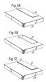
- Figs. 5A to 5C each shows another embodiment of the present invention.
- the conductive plate 12 and the connecting plate 13 are exposed to the outside while the metal plate is concealed by an extremely thin cover 21 which is made of synthetic resin.
- the slot antenna (metal plate, conductive plate and connecting plate) is fully enclosed by an extremely thin cover 22 which is also made of synthetic resin.
- all of the metal plate, conductive plate 12 and connecting plate 13 which constitute the slot antenna are exposed to the outside, the other part only being concealed by a cover 23 which is made of resin. While it is obvious that the configuration shown in Fig. 5C is thinnest, it will not feel so pleasant to the user because the metal is exposed.
Applications Claiming Priority (2)
| Application Number | Priority Date | Filing Date | Title |
|---|---|---|---|
| JP61303398A JPH0693635B2 (ja) | 1986-12-19 | 1986-12-19 | 小型無線機 |
| JP303398/86 | 1986-12-19 |
Publications (3)
| Publication Number | Publication Date |
|---|---|
| EP0272145A2 true EP0272145A2 (de) | 1988-06-22 |
| EP0272145A3 EP0272145A3 (en) | 1988-11-30 |
| EP0272145B1 EP0272145B1 (de) | 1993-03-03 |
Family
ID=17920543
Family Applications (1)
| Application Number | Title | Priority Date | Filing Date |
|---|---|---|---|
| EP87311202A Expired - Lifetime EP0272145B1 (de) | 1986-12-19 | 1987-12-18 | Funkempfänger vom Kartentyp mit eingebauter Schlitzantenne |
Country Status (6)
| Country | Link |
|---|---|
| US (1) | US4935745A (de) |
| EP (1) | EP0272145B1 (de) |
| JP (1) | JPH0693635B2 (de) |
| KR (1) | KR910006116B1 (de) |
| AU (1) | AU604810B2 (de) |
| CA (1) | CA1316219C (de) |
Cited By (7)
| Publication number | Priority date | Publication date | Assignee | Title |
|---|---|---|---|---|
| US4924237A (en) * | 1988-03-28 | 1990-05-08 | Matsushita Electric Works, Ltd. | Antenna and its electronic circuit combination |
| DE3922165A1 (de) * | 1989-07-06 | 1991-01-17 | Telefunken Systemtechnik | Aktiver planarer breitbandantennen-sensor fuer den mikrowellenbereich |
| WO1998027609A1 (en) * | 1996-12-18 | 1998-06-25 | Raytheon Company | Small omni-directional, slot antenna |
| EP0929121A1 (de) * | 1998-01-09 | 1999-07-14 | Nokia Mobile Phones Ltd. | Antenne für mobiles Kommunikationsgerät |
| US6140970A (en) * | 1999-04-30 | 2000-10-31 | Nokia Mobile Phones Limited | Radio antenna |
| CN1082261C (zh) * | 1994-10-31 | 2002-04-03 | 日本电气株式会社 | 带有内置天线的便携式无线接收机 |
| EP2645472A1 (de) * | 2012-03-29 | 2013-10-02 | Samsung Electronics Co., Ltd | Antennenvorrichtung eines mobilen Endgeräts |
Families Citing this family (26)
| Publication number | Priority date | Publication date | Assignee | Title |
|---|---|---|---|---|
| JP2624257B2 (ja) * | 1987-06-29 | 1997-06-25 | 日本電気株式会社 | 無線機用アンテナ |
| US4876552A (en) * | 1988-04-27 | 1989-10-24 | Motorola, Inc. | Internally mounted broadband antenna |
| JPH02234793A (ja) * | 1989-03-09 | 1990-09-17 | Matsushita Electric Ind Co Ltd | 電気洗濯機 |
| US5708833A (en) * | 1993-04-27 | 1998-01-13 | Norand Corporation | Antenna cap, antenna connectors and telephone line connectors for computer devices utilizing radio and modem cards |
| US5515303A (en) * | 1989-04-14 | 1996-05-07 | Norand Corporation | Hand-held computerized data collection terminal with rechargeable battery pack sensor and battery power conservation |
| US5043721A (en) * | 1989-12-18 | 1991-08-27 | Hewlett-Packard Company | Paging accessory for portable information/computing devices |
| US5192947A (en) * | 1990-02-02 | 1993-03-09 | Simon Neustein | Credit card pager apparatus |
| US5276919A (en) * | 1991-04-04 | 1994-01-04 | Motorola, Inc. | Radio with reusable breakaway switch |
| WO1993001662A1 (en) * | 1991-07-11 | 1993-01-21 | Shimon Neustein | Pager apparatus |
| US5469151A (en) * | 1991-11-07 | 1995-11-21 | Audiovox Corporation | Remote control car alarm system with wireless module interconnect |
| JP3173171B2 (ja) * | 1991-12-19 | 2001-06-04 | カシオ計算機株式会社 | 情報転送システム |
| US5268699A (en) * | 1992-09-24 | 1993-12-07 | Motorola, Inc. | Data communication receiver utilizing a loop antenna having a hinged connection |
| WO1994008361A1 (en) * | 1992-09-30 | 1994-04-14 | Motorola, Inc. | Low profile antenna system for a card-like communication receiver |
| US5418688A (en) * | 1993-03-29 | 1995-05-23 | Motorola, Inc. | Cardlike electronic device |
| US7119750B2 (en) * | 1993-04-27 | 2006-10-10 | Broadcom Corporation | Radio transceiver card communicating in a plurality of frequency bands |
| GB2292482A (en) * | 1994-08-18 | 1996-02-21 | Plessey Semiconductors Ltd | Antenna arrangement |
| US5483246A (en) * | 1994-10-03 | 1996-01-09 | Motorola, Inc. | Omnidirectional edge fed transmission line antenna |
| US5815120A (en) * | 1996-02-28 | 1998-09-29 | International Business Machines Corporation | Radio frequency local area network adapter card structure and method of manufacture |
| US6006074A (en) * | 1996-03-20 | 1999-12-21 | U.S. Philips Corporation | Apparatus having different shielding covers |
| FI974316A (fi) * | 1997-11-25 | 1999-05-26 | Lk Products Oy | Antennirakenne |
| US6230003B1 (en) * | 1998-04-16 | 2001-05-08 | Avaya Technology Corp. | Telephone calling card having a wireless receiver for receiving notification of arrived messages |
| US6304226B1 (en) * | 1999-08-27 | 2001-10-16 | Raytheon Company | Folded cavity-backed slot antenna |
| US7006846B2 (en) * | 2001-03-08 | 2006-02-28 | Northrop Grumman Corporation | Credit card communication system |
| JP3928426B2 (ja) | 2001-12-28 | 2007-06-13 | 松下電器産業株式会社 | アンテナ装置 |
| US7271774B2 (en) * | 2005-10-21 | 2007-09-18 | Suunto Oy | Electronic wearable device |
| CN202217782U (zh) * | 2010-05-24 | 2012-05-09 | Tdk株式会社 | 接近型天线以及无线通信设备 |
Citations (5)
| Publication number | Priority date | Publication date | Assignee | Title |
|---|---|---|---|---|
| US3736591A (en) * | 1970-10-30 | 1973-05-29 | Motorola Inc | Receiving antenna for miniature radio receiver |
| US4123756A (en) * | 1976-09-24 | 1978-10-31 | Nippon Electric Co., Ltd. | Built-in miniature radio antenna |
| JPS57103406A (en) * | 1980-12-18 | 1982-06-28 | Nippon Telegr & Teleph Corp <Ntt> | Antenna for radio equipment |
| GB2101436A (en) * | 1981-05-18 | 1983-01-12 | Nippon Electric Co | Portable radio receiver with high antenna gain |
| EP0176311A2 (de) * | 1984-09-17 | 1986-04-02 | Matsushita Electric Industrial Co., Ltd. | Mini-Antenne |
Family Cites Families (14)
| Publication number | Priority date | Publication date | Assignee | Title |
|---|---|---|---|---|
| SE435331B (sv) * | 1983-02-09 | 1984-09-17 | Ericsson Telefon Ab L M | Bildror for samtidig presentation av grafisk och alfanumerisk information |
| DE3465840D1 (en) * | 1983-03-19 | 1987-10-08 | Nec Corp | Double loop antenna |
| JPS607204A (ja) * | 1983-06-27 | 1985-01-16 | Toyo Commun Equip Co Ltd | 小型無線機のアンテナ |
| CA1243731A (en) * | 1983-08-29 | 1988-10-25 | Hideo Honma | Portable tape player with radio in lid |
| JPS60245321A (ja) * | 1984-05-18 | 1985-12-05 | Matsushita Electric Ind Co Ltd | 携帯用無線装置 |
| JPS6123423A (ja) * | 1984-07-11 | 1986-01-31 | Matsushita Electric Ind Co Ltd | 携帯無線機 |
| JPS6171702A (ja) * | 1984-09-17 | 1986-04-12 | Matsushita Electric Ind Co Ltd | 小形アンテナ |
| JPS6187434A (ja) * | 1984-10-04 | 1986-05-02 | Nec Corp | 携帯無線機 |
| US4660047A (en) * | 1984-10-12 | 1987-04-21 | Itt Corporation | Microstrip antenna with resonator feed |
| JPS61182302A (ja) * | 1985-02-07 | 1986-08-15 | Matsushita Electric Ind Co Ltd | 半導体集積回路 |
| DE3520983A1 (de) * | 1985-06-12 | 1986-12-18 | Robert Bosch Gmbh, 7000 Stuttgart | Antenne fuer ein funksende- und -empfangsgeraet |
| JPS62262502A (ja) * | 1986-05-09 | 1987-11-14 | Yuniden Kk | 無線通信機器用アンテナ |
| JPS62277803A (ja) * | 1986-05-26 | 1987-12-02 | Nippon Telegr & Teleph Corp <Ntt> | 携帯無線機 |
| US5005019A (en) * | 1986-11-13 | 1991-04-02 | Communications Satellite Corporation | Electromagnetically coupled printed-circuit antennas having patches or slots capacitively coupled to feedlines |
-
1986
- 1986-12-19 JP JP61303398A patent/JPH0693635B2/ja not_active Expired - Fee Related
-
1987
- 1987-12-18 EP EP87311202A patent/EP0272145B1/de not_active Expired - Lifetime
- 1987-12-18 CA CA000554771A patent/CA1316219C/en not_active Expired - Fee Related
- 1987-12-19 KR KR1019870014564A patent/KR910006116B1/ko not_active IP Right Cessation
- 1987-12-21 AU AU82851/87A patent/AU604810B2/en not_active Ceased
-
1989
- 1989-06-06 US US07/363,348 patent/US4935745A/en not_active Expired - Lifetime
Patent Citations (5)
| Publication number | Priority date | Publication date | Assignee | Title |
|---|---|---|---|---|
| US3736591A (en) * | 1970-10-30 | 1973-05-29 | Motorola Inc | Receiving antenna for miniature radio receiver |
| US4123756A (en) * | 1976-09-24 | 1978-10-31 | Nippon Electric Co., Ltd. | Built-in miniature radio antenna |
| JPS57103406A (en) * | 1980-12-18 | 1982-06-28 | Nippon Telegr & Teleph Corp <Ntt> | Antenna for radio equipment |
| GB2101436A (en) * | 1981-05-18 | 1983-01-12 | Nippon Electric Co | Portable radio receiver with high antenna gain |
| EP0176311A2 (de) * | 1984-09-17 | 1986-04-02 | Matsushita Electric Industrial Co., Ltd. | Mini-Antenne |
Non-Patent Citations (1)
| Title |
|---|
| PATENT ABSTRACTS OF JAPAN, vol. 6, no. 189 (E-133)[1067], 28th September 1982; & JP-A-57 103 406 (NIPPON DENSHIN DENWA KOSHA) 28-06-1982 * |
Cited By (10)
| Publication number | Priority date | Publication date | Assignee | Title |
|---|---|---|---|---|
| US4924237A (en) * | 1988-03-28 | 1990-05-08 | Matsushita Electric Works, Ltd. | Antenna and its electronic circuit combination |
| DE3922165A1 (de) * | 1989-07-06 | 1991-01-17 | Telefunken Systemtechnik | Aktiver planarer breitbandantennen-sensor fuer den mikrowellenbereich |
| CN1082261C (zh) * | 1994-10-31 | 2002-04-03 | 日本电气株式会社 | 带有内置天线的便携式无线接收机 |
| WO1998027609A1 (en) * | 1996-12-18 | 1998-06-25 | Raytheon Company | Small omni-directional, slot antenna |
| US6052093A (en) * | 1996-12-18 | 2000-04-18 | Savi Technology, Inc. | Small omni-directional, slot antenna |
| EP0929121A1 (de) * | 1998-01-09 | 1999-07-14 | Nokia Mobile Phones Ltd. | Antenne für mobiles Kommunikationsgerät |
| US6140970A (en) * | 1999-04-30 | 2000-10-31 | Nokia Mobile Phones Limited | Radio antenna |
| EP2645472A1 (de) * | 2012-03-29 | 2013-10-02 | Samsung Electronics Co., Ltd | Antennenvorrichtung eines mobilen Endgeräts |
| CN103367914A (zh) * | 2012-03-29 | 2013-10-23 | 三星电子株式会社 | 移动终端的天线装置 |
| US9882284B2 (en) | 2012-03-29 | 2018-01-30 | Samsung Electronics Co., Ltd. | Antenna device of mobile terminal |
Also Published As
| Publication number | Publication date |
|---|---|
| KR880008551A (ko) | 1988-08-31 |
| CA1316219C (en) | 1993-04-13 |
| AU604810B2 (en) | 1991-01-03 |
| EP0272145A3 (en) | 1988-11-30 |
| JPS63155919A (ja) | 1988-06-29 |
| AU8285187A (en) | 1988-06-23 |
| KR910006116B1 (ko) | 1991-08-13 |
| US4935745A (en) | 1990-06-19 |
| JPH0693635B2 (ja) | 1994-11-16 |
| EP0272145B1 (de) | 1993-03-03 |
Similar Documents
| Publication | Publication Date | Title |
|---|---|---|
| EP0272145B1 (de) | Funkempfänger vom Kartentyp mit eingebauter Schlitzantenne | |
| JP3114621B2 (ja) | 表面実装型アンテナおよびこれを用いた通信機 | |
| EP0697138B1 (de) | Tragbares sende-und/oder empfangsgerät | |
| US5589840A (en) | Wrist-type wireless instrument and antenna apparatus | |
| EP1858114B1 (de) | Antennenstruktur und damit ausgestattete drahtlose kommunikationsvorrichtung | |
| US4916456A (en) | Glass-mountable antenna assembly | |
| US5280646A (en) | Paging device with structure for removing static electricity | |
| JPH01241927A (ja) | 無線呼出用受信機 | |
| JP2003078333A (ja) | 無線通信機 | |
| JP2006319437A (ja) | アンテナ | |
| JP2001339226A (ja) | アンテナ装置 | |
| US5969680A (en) | Antenna device having a radiating portion provided between a wiring substrate and a case | |
| US7136681B2 (en) | Electrically conductive carrier and patterning for controlling current distribution in a wireless communications device | |
| JPH08111609A (ja) | アンテナ装置 | |
| US6175286B1 (en) | Dielectric resonator and dielectric filter using the same | |
| KR100346990B1 (ko) | 휴대무선기의안테나장치 | |
| US11881636B2 (en) | Printed circuit board antenna | |
| JP2002500836A (ja) | 無線通信装置 | |
| JP2917316B2 (ja) | アンテナ | |
| JPS60239106A (ja) | スロツトアンテナ | |
| JP2708770B2 (ja) | 回路一体型アンテナ | |
| WO2003058757A1 (fr) | Antenne | |
| JPH0591013U (ja) | 小型無線機用アンテナ | |
| JPH10341107A (ja) | 表面実装型アンテナおよびアンテナ装置 | |
| JPH0212729Y2 (de) |
Legal Events
| Date | Code | Title | Description |
|---|---|---|---|
| PUAI | Public reference made under article 153(3) epc to a published international application that has entered the european phase |
Free format text: ORIGINAL CODE: 0009012 |
|
| 17P | Request for examination filed |
Effective date: 19880113 |
|
| AK | Designated contracting states |
Kind code of ref document: A2 Designated state(s): GB NL SE |
|
| PUAL | Search report despatched |
Free format text: ORIGINAL CODE: 0009013 |
|
| AK | Designated contracting states |
Kind code of ref document: A3 Designated state(s): GB NL SE |
|
| 17Q | First examination report despatched |
Effective date: 19910703 |
|
| GRAA | (expected) grant |
Free format text: ORIGINAL CODE: 0009210 |
|
| AK | Designated contracting states |
Kind code of ref document: B1 Designated state(s): GB NL SE |
|
| PLBE | No opposition filed within time limit |
Free format text: ORIGINAL CODE: 0009261 |
|
| STAA | Information on the status of an ep patent application or granted ep patent |
Free format text: STATUS: NO OPPOSITION FILED WITHIN TIME LIMIT |
|
| 26N | No opposition filed | ||
| EAL | Se: european patent in force in sweden |
Ref document number: 87311202.3 |
|
| PGFP | Annual fee paid to national office [announced via postgrant information from national office to epo] |
Ref country code: NL Payment date: 20001231 Year of fee payment: 14 |
|
| REG | Reference to a national code |
Ref country code: GB Ref legal event code: IF02 |
|
| PG25 | Lapsed in a contracting state [announced via postgrant information from national office to epo] |
Ref country code: NL Free format text: LAPSE BECAUSE OF NON-PAYMENT OF DUE FEES Effective date: 20020701 |
|
| NLV4 | Nl: lapsed or anulled due to non-payment of the annual fee |
Effective date: 20020701 |
|
| PGFP | Annual fee paid to national office [announced via postgrant information from national office to epo] |
Ref country code: SE Payment date: 20031204 Year of fee payment: 17 |
|
| PGFP | Annual fee paid to national office [announced via postgrant information from national office to epo] |
Ref country code: GB Payment date: 20031217 Year of fee payment: 17 |
|
| PG25 | Lapsed in a contracting state [announced via postgrant information from national office to epo] |
Ref country code: GB Free format text: LAPSE BECAUSE OF NON-PAYMENT OF DUE FEES Effective date: 20041218 |
|
| PG25 | Lapsed in a contracting state [announced via postgrant information from national office to epo] |
Ref country code: SE Free format text: LAPSE BECAUSE OF NON-PAYMENT OF DUE FEES Effective date: 20041219 |
|
| EUG | Se: european patent has lapsed | ||
| GBPC | Gb: european patent ceased through non-payment of renewal fee |
Effective date: 20041218 |