EP0271690A1 - Etayage de la caisse d'un véhicule ferroviaire sur un bogie - Google Patents
Etayage de la caisse d'un véhicule ferroviaire sur un bogie Download PDFInfo
- Publication number
- EP0271690A1 EP0271690A1 EP87116191A EP87116191A EP0271690A1 EP 0271690 A1 EP0271690 A1 EP 0271690A1 EP 87116191 A EP87116191 A EP 87116191A EP 87116191 A EP87116191 A EP 87116191A EP 0271690 A1 EP0271690 A1 EP 0271690A1
- Authority
- EP
- European Patent Office
- Prior art keywords
- support
- vehicle
- bogie
- longitudinal direction
- spring
- Prior art date
- Legal status (The legal status is an assumption and is not a legal conclusion. Google has not performed a legal analysis and makes no representation as to the accuracy of the status listed.)
- Granted
Links
Images

Classifications
-
- B—PERFORMING OPERATIONS; TRANSPORTING
- B61—RAILWAYS
- B61F—RAIL VEHICLE SUSPENSIONS, e.g. UNDERFRAMES, BOGIES OR ARRANGEMENTS OF WHEEL AXLES; RAIL VEHICLES FOR USE ON TRACKS OF DIFFERENT WIDTH; PREVENTING DERAILING OF RAIL VEHICLES; WHEEL GUARDS, OBSTRUCTION REMOVERS OR THE LIKE FOR RAIL VEHICLES
- B61F5/00—Constructional details of bogies; Connections between bogies and vehicle underframes; Arrangements or devices for adjusting or allowing self-adjustment of wheel axles or bogies when rounding curves
- B61F5/02—Arrangements permitting limited transverse relative movements between vehicle underframe or bolster and bogie; Connections between underframes and bogies
- B61F5/14—Side bearings
- B61F5/148—Side bearings between bolsterless bogies and underframes
Definitions
- the invention relates to a support of the box of a rail vehicle on a bogie, with at least two laterally arranged, vertical and horizontal relative movements absorbing support units, each containing a spring element and at least one spring plate and at least one intermediate layer made of a rubber-elastic material, against which the spring plate against supports the adjacent vehicle part - box or bogie - inclinable in the longitudinal direction of the vehicle, the support unit having a smaller horizontal spring constant in the longitudinal direction of the vehicle than in the transverse direction of the vehicle.
- the different horizontal spring constants of the support units containing the spring elements are determined by support cams which are formed on the spring plates and run in the transverse direction and which, when the Allow bogies to allow the support unit to tilt elastically in the longitudinal direction of the vehicle, but prevent tilting in the transverse direction (DE-AS 15 30 102).
- the known support requires a relatively complex design of the elastic intermediate layers to be attached on each side of the support cam, each of which extends over half the spring plate.
- the respective outer dimensions of the two intermediate layers in the longitudinal direction of the vehicle corresponding to the diameter of the spring plate limit the largest possible angle of inclination of the spring plate to relatively small values, which can lead to strong deflections and correspondingly high stresses on the spring element, which is deformed in an S-shape, when driving on tight curves .
- the invention has for its object to provide a support that is improved in this respect in particular, which, without impairing the transmission of the vertical and horizontal supporting forces, enables greater inclinations of the spring plate in the longitudinal direction of the vehicle than before and which specifically influences the ratio of the longitudinal and transverse directions effective horizontal spring constants of the support unit allowed.
- the intermediate layer is formed by at least one rail-like support piece preloaded by compressive stresses under the full vertical support force of the loaded spring element, which is essentially rectangular in plan view and which has long sides oriented transversely to the vehicle longitudinal direction and essentially in Vehicle longitudinal direction oriented narrow sides is arranged.
- the design of the support according to the invention allows the use of simple, commercially available support elements made of rubber-like material, which are available in numerous dimension variants, for example in the form of plates or bars, and which - cut to the required size - can be used as supporting pieces without substantial reworking.
- Metallic contact between the bogies and the box is avoided by the support pieces according to the invention and sound insulation is thus achieved.
- a favorable load is achieved on the supporting elements that transmit the full vertical support force of the associated spring element and are therefore under compressive prestress.
- the spring plates incline, with restoring moments occurring in the support pieces as a result of changes in normal stress.
- the inclinable spring plates also significantly relieve the spring element of undesirable large transverse deflections in the longitudinal direction of the vehicle and the associated spring stresses.
- the ratio between the different horizontal spring constants of each of the support units which are effective in the longitudinal and transverse directions is determined by the ratio of the corresponding dimensions of the associated support piece.
- the advantages of the embodiment according to the invention can be achieved in particular by supporting pieces of rectangular shape which is relatively narrow in plan view.
- the restoring torque exerted by the support piece and counteracting the inclinations of the spring plate in the vehicle transverse direction can be at least four times greater than the corresponding restoring moment counteracting the inclinations of the spring plate in the vehicle longitudinal direction.
- the embodiment according to claim 3 is particularly advantageous for supports with more than one support unit per side of the bogie, since it allows a radial adjustment of the support pieces with respect to the axis of rotation of the bogie, and thus ensures a correspondingly favorable stress on the support pieces when turning the bogie.
- the embodiment according to claim 4 allows the use of a support piece, the length of which can be greater than the diameter of the spring plate determined by the dimensions of the spring element.
- the embodiment according to claim 5 allows an increase in the permissible pressure load of the support piece without significantly influencing its lateral and inclination stiffness.
- the embodiment according to claim 6 enables a precise positioning of the support piece and a securing of the spring element against lateral sliding of the spring plate in the event of damage or destruction of the support piece.
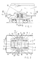
- each bogie 2 contains a bogie frame 3 with Side members 4, on which the box 1 is supported by two pairs of laterally arranged support units 9, each of which contains a spring element 5 formed from a helical spring.
- the bogie frame 3 is supported by known primary springs 6 on the axles of two wheel sets 7.
- the wheel sets 7 are coupled in a known manner with drive motors, not shown, attached to the bogie frame 3.
- the bogie frame 3 is rotatably connected to the box 1 about a vertical axis of rotation (vertical axis) Z via a device (not shown) for transmitting the tensile and braking forces, for example a deep-drawing device known, for example, from CH-PS 638 731.
- a device for transmitting the tensile and braking forces, for example a deep-drawing device known, for example, from CH-PS 638 731.
- the support units 8 also each contain two spring plates 8 arranged at the ends of the spring plates 5 and two rail-like support pieces 10 made of rubber or a corresponding rubber-like material, each between one of the spring plates 8 and the adjacent vehicle part - the box 1 or the rotary actuator 2 - are arranged.
- the support pieces 10 are arranged with long sides oriented transversely to the vehicle longitudinal direction x and correspondingly narrow sides oriented essentially in the longitudinal direction x. As can be seen in particular from FIG. 2, the support pieces 10 can be set so that they are essentially parallel to their long ones Lateral, elongated horizontal longitudinal axes 11 each intersect the vertical axis of rotation Z of the bogie 2.
- the support pieces 10 can each be attached to their upper and lower support surfaces, e.g. vulcanized or glued, preferably metallic outer stiffening plates 12 and 12a.
- the support pieces 10, the stiffening plates 12, 12a and the spring plates 8 can each be provided with at least one bore 13 penetrating them vertically, which for receiving one on the adjacent vehicle part, the box 1 or the bogie 2, fixed mandrel 14 is suitable.
- the diameter of the bores 13 in the spring plate 8, in the adjoining stiffening plate 12 and in the support piece 10 are larger than the diameter of the mandrel 14 by a relatively large amount of play, which allows the operational deformations of the support piece 10, while the plate 12a resting on the vehicle part According to this illustration, a diameter which is suitable for centering the support piece 10 and is only slightly larger than the mandrel 14 can have.
- a corresponding mandrel 14 can also be attached to the spring plate 8 and provided through the bores 13 of the support piece 10 and the stiffening plates 12, 12a into one on the adjacent vehicle part, on the box 1 or on the bogie 2 Protrude hole.
- the spring elements 5 of the support units 9 can also each have one be provided only support piece 10 and be supported directly with the other end via the spring plate 8 on the relevant vehicle part, in the example shown on box 1.
- the support pieces 10 can also each be provided with an inner stiffening plate 15 which divides their height H and between two sections 10a and 10b, for example vulcanized or glued in place.
- a plurality of corresponding stiffening plates 15 can also be provided.
- the rail-like support pieces 10 are each by a relatively large dimension, determined by their relatively small width B, essentially around the longitudinal axis 11 and by a dimension that is substantially smaller according to the ratio between the length L and the width B, by a dimension substantially parallel to the width B extending transverse axis 17 deformable.
- the rail-like support pieces 10 biased by the vertical supporting forces of the loaded spring elements 5 therefore permit relatively strong inclinations of the spring plate 8 with respect to the adjacent vehicle part - box 1 or bogie 2 - in the longitudinal direction x of the vehicle and correspondingly lower inclinations of the spring plate 8 in the transverse direction of the vehicle y and small entanglements of the stiffening plates 12, 12a about the axis A of the spring element 5.
- the unscrewing movements of the bogie 2 relative to the box 1 deflect the support units 9 both in the longitudinal direction x and in the transverse direction y, the ratio x the effective longitudinal horizontal stiffness C x and in the transverse direction y C y effective stiffness of each support unit 9 by the ratio between the width B and the length L of the associated supporting piece 10 is influenced.
- the support designed according to the invention can cause a relatively large mutual displacement V of the box 1 and the bogie 2 in the longitudinal direction of the bogie x by a relatively strong inclination of the spring element 5 and a correspondingly small mutual displacement U of the ends of the Spring element 5 are added.
- the conditions are indicated in the correspondingly inclined operating position of the interacting parts, in which the under normal load - e.g. 3 - straight central axis A of the spring element 5 runs in a slightly S-shaped curved line A ⁇ .
- a correspondingly favorable loading of the support pieces 10 is achieved by the "radial" setting of the support pieces 10 with respect to the axis of rotation Z.
- the support pieces 10 connected to the outer stiffening plates 12, 12a can, as can be seen from FIGS. 2 and 4, each be designed with a length L which is greater than the diameter of the associated spring plate 8, so that the for the predetermined ratio of horizontal stiffness C x / C y decisive dimensioning of the support pieces 10 can be made largely independent of the dimensions of the spring plate 8.
- Support pieces 10 with one or more inner stiffening plates 15 are particularly advantageous for designs with a relatively large height H, because this prevents the elastic material of the support pieces 10 from being squeezed out sideways and thus increases the pressure resistance of the support pieces 10.
- Relatively large heights H are preferably provided when large angles of inclination of the spring plates 8 in the vehicle longitudinal direction x are aimed for.
- the support pieces 10 can also each be provided with only one outer stiffening plate 12 or 12a and can be arranged with the unstiffened side directly on the spring plate 8 or on the adjacent vehicle part - box 1 or bogie 2 . Versions without external stiffening plates are also conceivable.
- the bores 13 formed in the support pieces 10 can also be designed as blind bores and can each be provided for receiving a securing part which only extends over part of the height H of the support piece 10.
- each bogie arranged support units 9 the support pieces 10 are set with long sides parallel to the transverse direction y of the vehicle.
- an embodiment with support units 9 arranged according to the representation according to FIGS. 1 and 2 is conceivable, the support pieces 10 of which are arranged with long sides running parallel to the transverse direction y.
- the support designed according to the invention is also suitable for bogies without a drive device.
Priority Applications (1)
| Application Number | Priority Date | Filing Date | Title |
|---|---|---|---|
| AT87116191T ATE58099T1 (de) | 1986-12-16 | 1987-11-04 | Abstuetzung des kastens eines schienenfahrzeuges auf einem drehgestell. |
Applications Claiming Priority (2)
| Application Number | Priority Date | Filing Date | Title |
|---|---|---|---|
| CH5005/86 | 1986-12-16 | ||
| CH5005/86A CH672100A5 (fr) | 1986-12-16 | 1986-12-16 |
Publications (2)
| Publication Number | Publication Date |
|---|---|
| EP0271690A1 true EP0271690A1 (fr) | 1988-06-22 |
| EP0271690B1 EP0271690B1 (fr) | 1990-11-07 |
Family
ID=4286299
Family Applications (1)
| Application Number | Title | Priority Date | Filing Date |
|---|---|---|---|
| EP87116191A Expired - Lifetime EP0271690B1 (fr) | 1986-12-16 | 1987-11-04 | Etayage de la caisse d'un véhicule ferroviaire sur un bogie |
Country Status (5)
| Country | Link |
|---|---|
| EP (1) | EP0271690B1 (fr) |
| JP (1) | JP2781385B2 (fr) |
| AT (1) | ATE58099T1 (fr) |
| CH (1) | CH672100A5 (fr) |
| DE (1) | DE3766082D1 (fr) |
Cited By (5)
| Publication number | Priority date | Publication date | Assignee | Title |
|---|---|---|---|---|
| DE4105350A1 (de) * | 1990-02-22 | 1991-09-19 | Sgp Verkehrstechnik | Sekundaerfederung fuer drehgestelle von schienenfahrzeugen |
| EP0533620A1 (fr) * | 1991-09-20 | 1993-03-24 | SLM Schweizerische Lokomotiv- und Maschinenfabrik AG | Dispositif de soutien d'une caisse de véhicule ferroviaire sur un bogie |
| US5638757A (en) * | 1993-10-21 | 1997-06-17 | Slm Schweizerische Lokomotiv- Und Maschinenfabrik Ag | Rail vehicle and truck for such a vehicle |
| FR2801268A1 (fr) * | 1999-11-23 | 2001-05-25 | Hutchinson | Appui pour une suspension secondaire d'un vehicule ferroviaire, notamment une locomotive |
| WO2023056566A1 (fr) * | 2021-10-07 | 2023-04-13 | National Research Council Of Canada | Ensemble rail, bogie, roue de bogie et ensemble joint gonflable |
Families Citing this family (2)
| Publication number | Priority date | Publication date | Assignee | Title |
|---|---|---|---|---|
| FR2960844B1 (fr) * | 2010-06-08 | 2012-07-06 | Hutchinson | Sommier basculant et suspension secondaire le comportant |
| KR101465526B1 (ko) * | 2013-05-28 | 2014-11-26 | 현대로템 주식회사 | 철도차량의 2차 코일스프링용 마운팅 구조 |
Citations (8)
| Publication number | Priority date | Publication date | Assignee | Title |
|---|---|---|---|---|
| US2698208A (en) * | 1953-02-12 | 1954-12-28 | Waugh Equipment Co | Side bearing |
| DE1144315B (de) * | 1957-12-04 | 1963-02-28 | Kloeckner Humboldt Deutz Ag | Abdichtung fuer die aus seitlichen Gleitstuecken bestehende Abstuetzung der Wagenkaesten von Schienenfahrzeugen auf Dreh- oder Schwenkgestellen |
| CH446424A (de) * | 1958-06-23 | 1967-11-15 | Metalastik Ltd | Schienenfahrzeug mit auf einem Drehgestell abgestütztem Fahrzeugkörper |
| FR2254466A1 (fr) * | 1973-12-12 | 1975-07-11 | Uerdingen Ag Waggonfabrik | |
| DE1530102B2 (de) * | 1966-03-11 | 1976-04-22 | Deutsche Bundesbahn, Vertreten Durch Das Bundesbahn-Zentralamt Minden, 4950 Minden | Sekundaerfederabstuetzung fuer schienenfahrzeuge |
| FR2366162A2 (fr) * | 1976-10-01 | 1978-04-28 | Venissieux Atel | Vehicule articule |
| DE3038634A1 (de) * | 1979-11-02 | 1981-05-14 | Inventio AG, 6052 Hergiswil, Nidwalden | Seitliche abstuetzung des wagenkastens eines schienenfahrzeuges mit wiegenlosem drehgestell |
| DE3346307A1 (de) * | 1983-12-22 | 1985-07-18 | M.A.N. Maschinenfabrik Augsburg-Nürnberg AG, 8500 Nürnberg | Vorrichtung zur begrenzung von wankbewegungen eines wagens mit wiegenlosen luftfederdrehgestellen |
Family Cites Families (2)
| Publication number | Priority date | Publication date | Assignee | Title |
|---|---|---|---|---|
| JPS5019106A (fr) * | 1973-06-22 | 1975-02-28 | ||
| JPS6114987A (ja) * | 1984-07-02 | 1986-01-23 | Nippon Kayaku Co Ltd | 熱転写画像形成方法 |
-
1986
- 1986-12-16 CH CH5005/86A patent/CH672100A5/de not_active IP Right Cessation
-
1987
- 1987-11-04 EP EP87116191A patent/EP0271690B1/fr not_active Expired - Lifetime
- 1987-11-04 AT AT87116191T patent/ATE58099T1/de not_active IP Right Cessation
- 1987-11-04 DE DE8787116191T patent/DE3766082D1/de not_active Expired - Lifetime
- 1987-12-15 JP JP62317279A patent/JP2781385B2/ja not_active Expired - Lifetime
Patent Citations (8)
| Publication number | Priority date | Publication date | Assignee | Title |
|---|---|---|---|---|
| US2698208A (en) * | 1953-02-12 | 1954-12-28 | Waugh Equipment Co | Side bearing |
| DE1144315B (de) * | 1957-12-04 | 1963-02-28 | Kloeckner Humboldt Deutz Ag | Abdichtung fuer die aus seitlichen Gleitstuecken bestehende Abstuetzung der Wagenkaesten von Schienenfahrzeugen auf Dreh- oder Schwenkgestellen |
| CH446424A (de) * | 1958-06-23 | 1967-11-15 | Metalastik Ltd | Schienenfahrzeug mit auf einem Drehgestell abgestütztem Fahrzeugkörper |
| DE1530102B2 (de) * | 1966-03-11 | 1976-04-22 | Deutsche Bundesbahn, Vertreten Durch Das Bundesbahn-Zentralamt Minden, 4950 Minden | Sekundaerfederabstuetzung fuer schienenfahrzeuge |
| FR2254466A1 (fr) * | 1973-12-12 | 1975-07-11 | Uerdingen Ag Waggonfabrik | |
| FR2366162A2 (fr) * | 1976-10-01 | 1978-04-28 | Venissieux Atel | Vehicule articule |
| DE3038634A1 (de) * | 1979-11-02 | 1981-05-14 | Inventio AG, 6052 Hergiswil, Nidwalden | Seitliche abstuetzung des wagenkastens eines schienenfahrzeuges mit wiegenlosem drehgestell |
| DE3346307A1 (de) * | 1983-12-22 | 1985-07-18 | M.A.N. Maschinenfabrik Augsburg-Nürnberg AG, 8500 Nürnberg | Vorrichtung zur begrenzung von wankbewegungen eines wagens mit wiegenlosen luftfederdrehgestellen |
Cited By (7)
| Publication number | Priority date | Publication date | Assignee | Title |
|---|---|---|---|---|
| DE4105350A1 (de) * | 1990-02-22 | 1991-09-19 | Sgp Verkehrstechnik | Sekundaerfederung fuer drehgestelle von schienenfahrzeugen |
| AT396096B (de) * | 1990-02-22 | 1993-05-25 | Sgp Verkehrstechnik | Sekundaerfederung fuer ein drehgestell eines schienenfahrzeuges |
| DE4105350C2 (de) * | 1990-02-22 | 1998-04-30 | Siemens Sgp Verkehrstech Gmbh | Sekundärfederung für Drehgestelle von Schienenfahrzeugen |
| EP0533620A1 (fr) * | 1991-09-20 | 1993-03-24 | SLM Schweizerische Lokomotiv- und Maschinenfabrik AG | Dispositif de soutien d'une caisse de véhicule ferroviaire sur un bogie |
| US5638757A (en) * | 1993-10-21 | 1997-06-17 | Slm Schweizerische Lokomotiv- Und Maschinenfabrik Ag | Rail vehicle and truck for such a vehicle |
| FR2801268A1 (fr) * | 1999-11-23 | 2001-05-25 | Hutchinson | Appui pour une suspension secondaire d'un vehicule ferroviaire, notamment une locomotive |
| WO2023056566A1 (fr) * | 2021-10-07 | 2023-04-13 | National Research Council Of Canada | Ensemble rail, bogie, roue de bogie et ensemble joint gonflable |
Also Published As
| Publication number | Publication date |
|---|---|
| ATE58099T1 (de) | 1990-11-15 |
| EP0271690B1 (fr) | 1990-11-07 |
| CH672100A5 (fr) | 1989-10-31 |
| JP2781385B2 (ja) | 1998-07-30 |
| DE3766082D1 (de) | 1990-12-13 |
| JPS63162367A (ja) | 1988-07-05 |
Similar Documents
| Publication | Publication Date | Title |
|---|---|---|
| DE3019468C2 (de) | Fahrwerk für Eisenbahnfahrzeuge | |
| DE1755897A1 (de) | Kautschukfederelement fuer Fahrzeugaufhaengung od.dgl. | |
| CH671195A5 (fr) | ||
| DE2142975C3 (de) | Abstützung des Wagenkastens auf dem Drehgestell eines Schienenfahrzeugs | |
| EP2604453A1 (fr) | Ressort à lame doté d'un corps de liaison élastique relié de manière rigide pour un véhicule automobile | |
| DE69924942T2 (de) | Blattfedergelenklager und Anordnung mit verstellbarem Führungselement | |
| DE1400214B1 (de) | Fahrzeugabfederung,insbesondere fuer Schienenfahrzeuge | |
| EP0271690B1 (fr) | Etayage de la caisse d'un véhicule ferroviaire sur un bogie | |
| DE102007003331B4 (de) | Vorrichtung zur gelenkigen Anbindung einer Kupplungsstange an ein Fahrzeug | |
| WO2012035056A1 (fr) | Véhicule sur rails en plusieurs parties comprenant au moins deux caisses reliées par une double articulation | |
| DE3543085A1 (de) | Rahmenartiges, flexibles achsaufhaengungssystem | |
| DE2923292C2 (fr) | ||
| DE1817187A1 (de) | Kautschukfeder fuer Aufhaengung von Kraftfahrzeugen od.dgl. | |
| DE2139337A1 (de) | Rotoranordnung für Hubschrauber od. dgl. und Schwingungsdämpfer hierfür | |
| EP0692574B1 (fr) | Joint de chaussée | |
| DE10247621A1 (de) | Kuppelstange mit Richtgelenken in Eisenbahntragwageneinheiten | |
| DE3637281A1 (de) | Am rahmen eines fahrgestells befestigbarer federbock | |
| DE1605044C3 (de) | Abstützung der Brücke von Schienenfahrzeugen | |
| DE2326729A1 (de) | Radsatzfuehrung fuer ein laufwerk, insbesondere ein drehgestell eines schienenfahrzeuges | |
| CH717246A2 (de) | Kuppelstange, insbesondere für ein Schienenfahrzeug. | |
| DE8429553U1 (de) | Kraftfahrzeug mit einem rahmen und einem aufbau | |
| DE1282667C2 (de) | Wiegenlose abstuetzung des wagenkastens eines schinenfahrzeugs auf einem drehgestell | |
| AT396096B (de) | Sekundaerfederung fuer ein drehgestell eines schienenfahrzeuges | |
| DE1605074B2 (de) | Drehzapfenlager, insbesondere fuer drehgestelle von schienenfahrzeugen | |
| CH617135A5 (en) | Rail power unit |
Legal Events
| Date | Code | Title | Description |
|---|---|---|---|
| PUAI | Public reference made under article 153(3) epc to a published international application that has entered the european phase |
Free format text: ORIGINAL CODE: 0009012 |
|
| AK | Designated contracting states |
Kind code of ref document: A1 Designated state(s): AT DE FR GB IT SE |
|
| 17P | Request for examination filed |
Effective date: 19881210 |
|
| 17Q | First examination report despatched |
Effective date: 19900116 |
|
| GRAA | (expected) grant |
Free format text: ORIGINAL CODE: 0009210 |
|
| AK | Designated contracting states |
Kind code of ref document: B1 Designated state(s): AT DE FR GB IT SE |
|
| REF | Corresponds to: |
Ref document number: 58099 Country of ref document: AT Date of ref document: 19901115 Kind code of ref document: T |
|
| ITF | It: translation for a ep patent filed |
Owner name: ING. ZINI MARANESI & C. S.R.L. |
|
| ET | Fr: translation filed | ||
| REF | Corresponds to: |
Ref document number: 3766082 Country of ref document: DE Date of ref document: 19901213 |
|
| GBT | Gb: translation of ep patent filed (gb section 77(6)(a)/1977) | ||
| PLBE | No opposition filed within time limit |
Free format text: ORIGINAL CODE: 0009261 |
|
| STAA | Information on the status of an ep patent application or granted ep patent |
Free format text: STATUS: NO OPPOSITION FILED WITHIN TIME LIMIT |
|
| 26N | No opposition filed | ||
| ITTA | It: last paid annual fee | ||
| EAL | Se: european patent in force in sweden |
Ref document number: 87116191.5 |
|
| REG | Reference to a national code |
Ref country code: GB Ref legal event code: IF02 |
|
| REG | Reference to a national code |
Ref country code: GB Ref legal event code: 746 Effective date: 20030807 |
|
| PGFP | Annual fee paid to national office [announced via postgrant information from national office to epo] |
Ref country code: GB Payment date: 20031029 Year of fee payment: 17 |
|
| PGFP | Annual fee paid to national office [announced via postgrant information from national office to epo] |
Ref country code: SE Payment date: 20031103 Year of fee payment: 17 Ref country code: DE Payment date: 20031103 Year of fee payment: 17 |
|
| PGFP | Annual fee paid to national office [announced via postgrant information from national office to epo] |
Ref country code: AT Payment date: 20031105 Year of fee payment: 17 |
|
| PGFP | Annual fee paid to national office [announced via postgrant information from national office to epo] |
Ref country code: FR Payment date: 20031107 Year of fee payment: 17 |
|
| PG25 | Lapsed in a contracting state [announced via postgrant information from national office to epo] |
Ref country code: GB Free format text: LAPSE BECAUSE OF NON-PAYMENT OF DUE FEES Effective date: 20041104 Ref country code: AT Free format text: LAPSE BECAUSE OF NON-PAYMENT OF DUE FEES Effective date: 20041104 |
|
| PG25 | Lapsed in a contracting state [announced via postgrant information from national office to epo] |
Ref country code: SE Free format text: LAPSE BECAUSE OF NON-PAYMENT OF DUE FEES Effective date: 20041105 |
|
| PG25 | Lapsed in a contracting state [announced via postgrant information from national office to epo] |
Ref country code: DE Free format text: LAPSE BECAUSE OF NON-PAYMENT OF DUE FEES Effective date: 20050601 |
|
| GBPC | Gb: european patent ceased through non-payment of renewal fee |
Effective date: 20041104 |
|
| EUG | Se: european patent has lapsed | ||
| PG25 | Lapsed in a contracting state [announced via postgrant information from national office to epo] |
Ref country code: FR Free format text: LAPSE BECAUSE OF NON-PAYMENT OF DUE FEES Effective date: 20050729 |
|
| REG | Reference to a national code |
Ref country code: FR Ref legal event code: ST |
|
| PG25 | Lapsed in a contracting state [announced via postgrant information from national office to epo] |
Ref country code: IT Free format text: LAPSE BECAUSE OF NON-PAYMENT OF DUE FEES;WARNING: LAPSES OF ITALIAN PATENTS WITH EFFECTIVE DATE BEFORE 2007 MAY HAVE OCCURRED AT ANY TIME BEFORE 2007. THE CORRECT EFFECTIVE DATE MAY BE DIFFERENT FROM THE ONE RECORDED. Effective date: 20051104 |