EP0270943A1 - Procédé et dispositif pour former des piles d'articles en feuilles (feuilles) - Google Patents
Procédé et dispositif pour former des piles d'articles en feuilles (feuilles) Download PDFInfo
- Publication number
- EP0270943A1 EP0270943A1 EP87117539A EP87117539A EP0270943A1 EP 0270943 A1 EP0270943 A1 EP 0270943A1 EP 87117539 A EP87117539 A EP 87117539A EP 87117539 A EP87117539 A EP 87117539A EP 0270943 A1 EP0270943 A1 EP 0270943A1
- Authority
- EP
- European Patent Office
- Prior art keywords
- stack
- jaw
- removal
- arrangement according
- belts
- Prior art date
- Legal status (The legal status is an assumption and is not a legal conclusion. Google has not performed a legal analysis and makes no representation as to the accuracy of the status listed.)
- Granted
Links
Images


Classifications
-
- B—PERFORMING OPERATIONS; TRANSPORTING
- B65—CONVEYING; PACKING; STORING; HANDLING THIN OR FILAMENTARY MATERIAL
- B65H—HANDLING THIN OR FILAMENTARY MATERIAL, e.g. SHEETS, WEBS, CABLES
- B65H31/00—Pile receivers
- B65H31/30—Arrangements for removing completed piles
- B65H31/3054—Arrangements for removing completed piles by moving the surface supporting the lowermost article of the pile, e.g. by using belts or rollers
-
- B—PERFORMING OPERATIONS; TRANSPORTING
- B65—CONVEYING; PACKING; STORING; HANDLING THIN OR FILAMENTARY MATERIAL
- B65H—HANDLING THIN OR FILAMENTARY MATERIAL, e.g. SHEETS, WEBS, CABLES
- B65H31/00—Pile receivers
- B65H31/30—Arrangements for removing completed piles
- B65H31/3081—Arrangements for removing completed piles by acting on edge of the pile for moving it along a surface, e.g. by pushing
-
- B—PERFORMING OPERATIONS; TRANSPORTING
- B65—CONVEYING; PACKING; STORING; HANDLING THIN OR FILAMENTARY MATERIAL
- B65H—HANDLING THIN OR FILAMENTARY MATERIAL, e.g. SHEETS, WEBS, CABLES
- B65H31/00—Pile receivers
- B65H31/32—Auxiliary devices for receiving articles during removal of a completed pile
-
- B—PERFORMING OPERATIONS; TRANSPORTING
- B65—CONVEYING; PACKING; STORING; HANDLING THIN OR FILAMENTARY MATERIAL
- B65H—HANDLING THIN OR FILAMENTARY MATERIAL, e.g. SHEETS, WEBS, CABLES
- B65H2402/00—Constructional details of the handling apparatus
- B65H2402/60—Coupling, adapter or locking means
-
- B—PERFORMING OPERATIONS; TRANSPORTING
- B65—CONVEYING; PACKING; STORING; HANDLING THIN OR FILAMENTARY MATERIAL
- B65H—HANDLING THIN OR FILAMENTARY MATERIAL, e.g. SHEETS, WEBS, CABLES
- B65H2406/00—Means using fluid
- B65H2406/10—Means using fluid made only for exhausting gaseous medium
-
- B—PERFORMING OPERATIONS; TRANSPORTING
- B65—CONVEYING; PACKING; STORING; HANDLING THIN OR FILAMENTARY MATERIAL
- B65H—HANDLING THIN OR FILAMENTARY MATERIAL, e.g. SHEETS, WEBS, CABLES
- B65H2406/00—Means using fluid
- B65H2406/10—Means using fluid made only for exhausting gaseous medium
- B65H2406/11—Means using fluid made only for exhausting gaseous medium producing fluidised bed
-
- B—PERFORMING OPERATIONS; TRANSPORTING
- B65—CONVEYING; PACKING; STORING; HANDLING THIN OR FILAMENTARY MATERIAL
- B65H—HANDLING THIN OR FILAMENTARY MATERIAL, e.g. SHEETS, WEBS, CABLES
- B65H2406/00—Means using fluid
- B65H2406/10—Means using fluid made only for exhausting gaseous medium
- B65H2406/12—Means using fluid made only for exhausting gaseous medium producing gas blast
- B65H2406/122—Nozzles
Definitions
- the invention relates to a method for forming stacks of sheet material (sheets) at a collection point and for removing the stacks.
- the invention also relates to an arrangement for forming and conveying stacks of sheet material (sheets) with a collecting device and a conveyor.
- Sheet-shaped material is understood to mean single sheets or single sheets of paper, film, plastic, which have a flat shape.
- the term “stack” means collections of sheets lying one above the other. So-called “layers” made up of relatively few sheets lying one above the other should also fall under the collective term “stack”.
- the object of the invention is a quick u. To ensure the safe removal of stacks from a collection point without disrupting the collection process. According to the invention, this object is achieved in that a stack is supported on a lower surface during conveyance and is held on a surface.
- a stack to be conveyed is supported at least on the largest part of its lower surface, while it is only held on a relatively small part of its surface.
- the support can cover the entire bottom surface of the stack.
- the stack is advantageously held in an edge zone of its surface which lies in the conveying direction.
- the holding surface holding the stack on its surface advantageously consists of a jaw, which separates the stack from sheets collected above it during and after the stack is formed.
- the jaw then has a holding function when the stack is being removed, while, according to a particularly advantageous development of the invention, a further jaw separates a further stack of sheets accumulated above it.
- the further jaw serves as a separating jaw for the following stack, hereinafter referred to as "further stack”.
- the further jaw After removal of the first stack, the further jaw then serves to hold the removal of the further stack.
- a cheek after performing its holding function, is transferred into a position in which it performs a separating function for the further stack.
- the two jaws then alternate in their holding and separating function, a jaw advantageously not changing its position with respect to the stack below it until it detaches from it during removal.
- the undersurface of a stack can be supported in the removal of belts that can be guided over rollers that are in one preferably horizontally movable car are stored.
- the tapes can then advantageously be removed first with the stack, whereby they are not driven relative to the carriage. Only when the stack is sufficiently far away from its removal position can they be driven according to a further development of the invention in order to also remove the stack from the belts.
- a particularly advantageous development of the invention which is generally applicable for the promotion of stacks of sheets and which therefore has independent inventive content, is that the belts stand still relative to a carriage carrying them until the stacks are first removed from the surface of the stack co-moving jaw has detached from the stack, and that the belts are then driven with the stack relative to the carriage in the conveying direction.
- This further development avoids having to first stop the stacks with the car and then accelerate them again through the belts, which means that a relatively large amount of time is lost due to the limited deceleration and acceleration values (risk of slipping).
- the stacks can be accelerated relative to the moving carriage after releasing the holding jaws after the initial relative standstill between the belts and the carriage, so that when the carriage has reached its end position, it can be transferred to another conveyor at the speed reached and decelerated as well as new acceleration. If a stack has been removed from the scaffolding or carriage by the driven belts, the belts are moved back to the collection point. They have to get under the lower surface of the stack that has now been brought up, ie generally lowered gene, wherein a relative movement in the conveying direction of the stack, that is generally in the horizontal direction, is undesirable in order to avoid impairment of the lower surface of the further stack.
- this sub-problem is solved in that the carriage with the belts guided over rollers is moved to the collecting station while the belts are being held, so that belt sections without relative movements in the conveying direction with respect to the lower surface of the further stack on the lower surface thereof Create continuously. Damage to this lower surface is thus reliably avoided.
- the further stack is supported according to the invention at least on the largest part of its lower surface, while it is lowered into the removal position.
- a lowerable table can be used, from the surface of which compressed air flows if a relative movement between the table and the stack is to take place in or parallel to the discharge direction.
- the compressed air reduces the friction between the table surface and the lower surface of the stack so much that impairment of the lower surface during a relative movement is practically impossible.
- the table and belts can be driven synchronously so that the belts support the stack being removed, while the table supports the further stack in the area released by the stack underneath.
- compressed air can be blown in between the stacks in order to reduce the friction.
- the further stack located above the stack, which is in the removal position can be held by at least one separating finger until it is lowered into the removal position. Compressed air can advantageously be used from this separating finger for better separation of the stacks or Reduce the friction between them being blown.
- a further improvement in the removal of the stack from its removal position is obtained by pushing the stack on a boundary surface facing away from the conveying direction
- the invention has several advantages:
- the stack to be removed is held securely during removal. Its sheets can hardly move even with a larger stack height, so that there is no fear of slipping of sheets or sheet layers within the stack.
- the special configurations of the invention (blown air between the stacks. Support by air table) reliably prevent impairment of the bottom or surface of the stacks when the bottom stack is being removed.
- the jaws Since the jaws have an alternating separating and then holding function, one jaw changing its position with respect to each does not change the stack under it during the transition from the separating to the holding function, in addition to the safety, the speed at which the stack can be removed is increased. Due to the specific design of the trolley and the belt drive, in which when a stack is removed, its speed does not change until it is delivered to a conveyor, i.e. its speed is at least largely independent of the speed changes of the trolley carrying the belts, only work at high removal speeds manageable acceleration and deceleration forces on the stack, which reduces the risk of slipping.
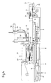
- a stack of sheets 1 is located at a collecting station or collecting point SS in its removal position AP, in which it is ready for removal in the conveying direction FR. It rests with its lower surface 2 on belts 3 (only one visible) arranged one behind the other in the plane of the drawing, which form a base and are guided over rollers 4 ... 8.
- the rollers 4 and 6 are rotatably mounted in a carriage 9, the roller 4 being fixable by an electrically controllable brake 10.
- the rollers 6, 7 and 8 are mounted in a stationary manner, the roller 8 being drivable by a drive in the form of an electric motor 11 and being fixable by an electrically controllable brake 12.
- a drive for the carriage 9 in the form of an electric motor 13 is guided with a spindle 14 through a spindle nut 16 fastened to the carriage, so that it can drive the carriage in the conveying direction FR or in the opposite direction RF, depending on the direction of rotation Rollers 17 on a tread 18.
- Guide surfaces for the stack 1 are designated 19, 21 and 22.
- a conveyor belt 23 in a transfer position ÜP serves to remove the stack 1 transferred from the carriage 9.
- Attached to the carriage 9 is a support surface in the form of a so-called air table 26, which is known per se. Tables of this type have an interior which is connected to a compressed air source 27, which is indicated by a flexible hose line 28.
- the surface of such known air tables has bores 29 which are closed by spring-loaded balls, not shown. If these balls are under the winding of a load, e.g. B. a stack of sheets, depressed, compressed air flows from the holes, which forms an air film that reduces the friction between the table surface and the bottom surface of the stack.
- the air table is connected to the carriage 9 so that it runs along with the carriage in the conveying direction FR, with rollers 31 of the air table running on rails 32.
- the air table can be displaced vertically relative to the carriage 9 by means of suitable guides, designated 35, when a lowering device 33, which can also function as a lifting device, lowers or raises the rails 32.
- the lowering device is designed as lowerable and liftable scissors 34 with the legs 36 and 37.
- the legs 36 are rotatably mounted on the rails 32 by means of joints 38 and are guided in sliding guides 41 on a bottom surface 39.
- the legs 37 are rotatably mounted on the bottom surface 39 by means of joints 42 and are mounted on the rails 32 by means of sliding guides 43 so that they can be moved.
- a drive in the form of an electric motor 44 a spindle nut 46 and a spindle 47, the rails 32 and with them the air table 26 can be raised and lowered by approximately a stack height.
- the jaw 53 rests with its holding surfaces on the surface 55 of the stack 1 in an edge zone RZ located in the conveying direction FR, in which it has a separating function as shown in FIG.
- the Parting fingers 52 are connected via a flexible line 56 to a compressed air source 57, so that they can blow compressed air from their interior through ducts between stacks 1 and 51, which reduces the adhesion and friction between these stacks.
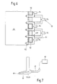
- the forks 54 of the jaw 53 of which FIG. 7 shows details, also have a flexible connection 81, shown in FIG.
- the forks 54 of the jaw 53 are connected to a common pneumatic drive 58 for movement in the horizontal direction and to a pneumatic drive 59 for movement in the vertical direction.
- the separating fingers 52 have a common pneumatic drive 62 for movement in the horizontal direction.
- the further jaw 63 On the further stack 51 there is a further jaw 63 in a position in which it performs a separating function, wherein it separates the further stack 51 from a new stack of sheets 61 which is just being formed.
- the further jaw 63 also consists of forks 64 which are connected to a common pneumatic drive 66 for movement in the horizontal direction and to a common pneumatic drive 67 for movement in the vertical direction.
- the jaw 63 like the jaw 53, is connected to a compressed air source 82 via an air connection 81 shown in FIG. 7, so that compressed air can be blown out of the jaw when it is in its separation position.
- the pneumatic drives 58, 59, 62, 66 and 67 receive their compressed air for the back and forth movements to be initiated by them via schematically indicated air lines 58a, 58b or 59a, 59b or 62a, 62b or 66a, 66b or 67a, 67b from a compressed air transmitter 68, the outputs of which are controlled by a control arrangement 69.
- the control arrangement also controls the electric drive motors 11, 13 and 44 via schematically indicated lines 11a or 13a or 44a and the controllable brakes 10 and 12 via schematically indicated control lines 10a or 12a.
- the above-mentioned pneumatic and electric drives are controlled as a function of the machine cycles in which sheets 71 are fed to the collecting station SS from a conveyor belt 74 guided over rollers 72 and 73.
- the leaves are e.g. B. from a rotary cutter, not shown, from a continuous web of material, for. B. a paper web, cut off and are collected into a new stack 61 over the other jaw 63 in its separating position.
- 75 and 76 so-called plates are referred to, which are usually designed as sheets that are vibrated by a vibrator and have the task of aligning the sheets of the stack after accumulation, so that the boundary surfaces are as smooth as possible.
- 77 is a slide which has the task of supporting the removal of the stack 1 by pressing on the surface 78 of the stack 1.
- FIG. 6 shows a top view of the forks 64 of the further jaw 63 resting on the further stack 51, of the separating fingers 52 and of the forks 54 of the jaw 53, approximately in the position of FIG. 4. The flowing air is also indicated.
- FIG. 7 shows an enlarged side view of a jaw 53, 63 with an air outlet 80, an air duct 79, a flexible line 81 (for example a hose) line) and a compressed air source 82.
- FIGS. 1 to 5 illustrate the movement sequences.
- FIGS. 2 to 5 omit the pneumatic lines from the compressed air transmitter 68 to the pneumatic drives and the electrical lines from the control arrangement 69 to the electrical drives and the controllable brakes.
- the stack 1 to be removed is in its removal position AP, from which it, resting on the belts 3, is conveyed by means of the carriage 9 to its transfer position UP and transferred there to the removal belt 23 and transferred for further processing, e.g. B. zue packaging is removed.
- the separating fingers 52 and the jaw 53 are located in an edge zone RZ above the stack 1 in a separating position in which they perform their separating function in an intermediate space ZW between the stack 1 and a further stack 51 which has the same height as stack 1 protrude. Compressed air flows from the separating fingers 52 and the forks 54 of the jaw 53 into the intermediate space ZW to reduce the friction between the lower surface of the stack 51 and the surface 55 of the stack 1, which also makes it easier to separate the two stacks from one another, which will be described later.
- the forks 64 of the further jaw 63 are in a separating position in which they protrude into the intermediate space ZW between the further stack 51 and a new stack 61 that is being formed in order to perform their separating function; Compressed air is also blown into this space to reduce friction and improve separation.
- the electric motor 13 of the carriage 9 receives a control signal from the control arrangement 69 via line 13a so that it starts up and sets the carriage in motion in the removal direction FR.
- the pneumatic drive 58 of the jaw 53 receives compressed air via line 58a from the compressed air generator 68, so that the jaw 53 is moved synchronously with the carriage 9 in the FR direction, resting on the edge zone RZ of the stacking surface 55 and thus performing its holding function.
- the brake 10 of the roller 4 is tightened so that the belts 3 with the stack 1 are still at rest relative to the carriage 9.
- the brake 12 receives a control signal for release from the control arrangement 69 via line 12a; at the same time, the electric motor 11 receives a control signal via line 11a, so that it starts up and sets the roller 8 under tension.
- the drive for the belts 3 can also be designed such that the electric motor 11 always runs through and the transmission of its torque to the belts 3 only takes place via the controllable brake 12.
- the speed of the electric motor 11 is selected so that the roller 8 has a slightly higher peripheral speed than the speed of the carriage 9 in the FR direction, so that the upper strands of the belts 3 are always taut.
- the jaw 53 thus acts as a holding jaw in the manner described above, so that the stack 1 can be safely detached from the stack 51 above and accelerated.
- the separation is supported by the compressed air from the separation fingers 52 and possibly from the jaw 53.
- the removal of the stack 1 is supported by the slide 77, which presses on the stacking surface 78.
- the air table 26 according to FIG. 2 increasingly passes under the further stack 51, air flowing out of the bores 29 of the covered surfaces reduces the friction between the table surface and the stacking surface.
- Figure 3 shows that the jaw 53 is lifted by the pneumatic drive 67 from the surface 55 of the stack 1 after the start of the conveyance, since its holding function is only required during the beginning and the first phase of the conveyance. After a stroke, it is conveyed back by approximately one stack height from the drive 58 in the horizontal direction to the collecting station SS and conveyed over the edge zone RZ of the new stack 61 (FIGS. 4 and 5) as soon as it has reached its prescribed size. In this position, the jaw 53 performs a separating function by separating the new stack 61 from further sheets 71 fed from above to the collecting station SS. The separation function is supported by the compressed air flowing out of the forks 54 of the jaw 53.
- the brake 10 is released by a control signal via line 10a, so that the belts 3 can now carry out a relative movement to the carriage 9 in the discharge direction FR, the carriage moving further from the electric motor 13 in the direction FR is moved.
- the speed of the tapes can be controlled so that they are in space, for. B. based on the tread 18, is substantially constant regardless of the speed at which the carriage is moved to the transfer position ÜP.
- the belts 3 can push the stack 1 onto the conveyor belt 23 practically without changes in speed over the guide surfaces 21 and 22, which then removes it for further processing.
- the further stack 51 which is now completely on the air table 26, must be lowered into the removal position AP, for which purpose the electric drive motor 44 is switched on.
- This motor rotates the spindle 47, which pulls the scissors 34 downward by the height of the further stack 51, as a result of which the latter reaches the discharge position AP shown in FIG. 4.
- the separating fingers 52 are removed by their pneumatic drive 62, which receives compressed air via line 62a, from the intermediate space ZW between the stacks until the further stack 51 has reached its removal position AP. In this position, the pneumatic drive 62 moves the separating fingers 52 back into the position between the stacks as shown in FIG.
- the pneumatic drive 67 of the further jaw 63 lowers it in synchronism with the one below Chen further stack 51, so that the jaw 63 maintains its separating function until it performs its holding function when the further stack 51 is subsequently removed.
- 4 has left the belts 3 of the carriage 7, the carriage 9 is moved back in the opposite direction RF by the electric motor 13, which receives a corresponding control signal via line 13a.
- the roller 8 is fixed via the controllable brake 12, which receives a control signal via line 12a, while the brake 10 remains open.
- belt sections of the belts 3 lie in succession from below against the lower surface of the further stack 51 without executing a relative movement in the opposite direction RF, so that the risk of damage to the lower surface is excluded.
- the jaws 53 and 63 perform their separating and holding functions one after the other and alternate. It is particularly advantageous that the jaws 53, 63 do not change their relative position with respect to the edge zones RZ of the stack, neither during their separation nor during their holding function, which has a favorable influence on the movement sequences of the stack and also allows higher speeds.
Landscapes
- Engineering & Computer Science (AREA)
- Mechanical Engineering (AREA)
- Sheets, Magazines, And Separation Thereof (AREA)
- Pile Receivers (AREA)
- Forming Counted Batches (AREA)
Applications Claiming Priority (2)
| Application Number | Priority Date | Filing Date | Title |
|---|---|---|---|
| DE3642259 | 1986-12-11 | ||
| DE19863642259 DE3642259A1 (de) | 1986-12-11 | 1986-12-11 | Verfahren und anordnung zum bilden von stapeln aus blattfoermigem material (blaettern) |
Publications (2)
| Publication Number | Publication Date |
|---|---|
| EP0270943A1 true EP0270943A1 (fr) | 1988-06-15 |
| EP0270943B1 EP0270943B1 (fr) | 1991-08-21 |
Family
ID=6315920
Family Applications (1)
| Application Number | Title | Priority Date | Filing Date |
|---|---|---|---|
| EP87117539A Expired - Lifetime EP0270943B1 (fr) | 1986-12-11 | 1987-11-27 | Procédé et dispositif pour former des piles d'articles en feuilles (feuilles) |
Country Status (4)
| Country | Link |
|---|---|
| US (1) | US4878659A (fr) |
| EP (1) | EP0270943B1 (fr) |
| JP (1) | JPS63202561A (fr) |
| DE (2) | DE3642259A1 (fr) |
Cited By (5)
| Publication number | Priority date | Publication date | Assignee | Title |
|---|---|---|---|---|
| EP0392139A2 (fr) * | 1989-04-12 | 1990-10-17 | JAGENBERG Aktiengesellschaft | Dispositif pour déposer des liasses de feuilles, en particulier des feuilles en papier, sur une pile |
| EP0579031A2 (fr) * | 1992-07-10 | 1994-01-19 | Focke & Co. (GmbH & Co.) | Procédé et dispositif pour manipuler des piles de découpes |
| EP0869095A2 (fr) * | 1997-02-28 | 1998-10-07 | BIELOMATIK LEUZE GmbH + Co. | Empileur |
| WO2000078657A1 (fr) * | 1999-06-21 | 2000-12-28 | E.C.H. Will Gmbh | Procede et dispositif pour changer des palettes destinees a des piles de feuilles |
| EP2520526A1 (fr) * | 2010-05-12 | 2012-11-07 | Macarbox, S.L.U. | Machine d'empilage d'articles plats |
Families Citing this family (13)
| Publication number | Priority date | Publication date | Assignee | Title |
|---|---|---|---|---|
| NO901737L (no) * | 1990-04-19 | 1991-10-21 | Norlito Maskin As | Pakkemaskin for blader (stakker). |
| US5092236A (en) * | 1990-06-06 | 1992-03-03 | Quipp Systems, Inc. | Method and apparatus for stacking, aligning and compressing signatures |
| DE4021676C1 (fr) * | 1990-07-07 | 1991-11-21 | Hilmar 5653 Leichlingen De Vits | |
| DE4022350A1 (de) * | 1990-07-13 | 1992-01-16 | Bielomatik Leuze & Co | Foerdereinrichtung fuer lageneinheiten |
| DE4131015C2 (de) * | 1991-09-18 | 1995-10-05 | Roland Man Druckmasch | Bogenausleger |
| DE4217816C2 (de) * | 1992-05-29 | 1995-01-26 | Heidelberger Druckmasch Ag | Einrichtung zur kontinuierlichen Auslage flächiger Druckprodukte |
| US5882175A (en) * | 1997-01-13 | 1999-03-16 | Ward Holding Company | Stacker for flexible sheets |
| US6227373B1 (en) * | 1997-07-14 | 2001-05-08 | Delta Design, Inc. | Electronic device handling system and method |
| US6662428B2 (en) * | 2000-07-31 | 2003-12-16 | Fuji Photo Film Co., Ltd. | System for manufacturing film case |
| SE523475C2 (sv) * | 2000-09-18 | 2004-04-20 | Straalfors Ab | Anordning för stackning av ark |
| DE10307785A1 (de) * | 2003-02-14 | 2004-08-26 | E.C.H. Will Gmbh | Vorrichtung zum Stapeln eines einlaufenden Bogenstroms |
| DE102016214970A1 (de) * | 2016-08-11 | 2018-02-15 | Koenig & Bauer Ag | Auslagevorrichtung mit zumindest einer Abgabestation und ein Verfahren zur Auslage von Bedruckstoffbogen in einer Auslagevorrichtung |
| JP7228396B2 (ja) * | 2019-02-01 | 2023-02-24 | 三菱重工機械システム株式会社 | シート積重装置、カウンタエゼクタ、製函機 |
Citations (3)
| Publication number | Priority date | Publication date | Assignee | Title |
|---|---|---|---|---|
| DE2942965A1 (de) * | 1979-10-24 | 1981-05-07 | Automation für grafische Technik AG, 4005 Meerbusch | Stapeleinrichtung insbesondere fuer druckmaschinen |
| DE3046107A1 (de) | 1980-12-06 | 1982-06-09 | Bielomatik Leuze Gmbh + Co, 7442 Neuffen | Stapelvorrichtung fuer boegen |
| DE3221351A1 (de) * | 1982-06-05 | 1983-12-08 | Icoma Packtechnik GmbH, 7590 Achern | Transportvorrichtung fuer papiersackpakete |
Family Cites Families (4)
| Publication number | Priority date | Publication date | Assignee | Title |
|---|---|---|---|---|
| US3580402A (en) * | 1969-01-30 | 1971-05-25 | Gen Foods Corp | Apparatus for automatically stacking and inverting stacked units of sheet material |
| DE3049633A1 (en) * | 1979-06-13 | 1982-02-25 | G Byrt | Sheet stacking apparatus |
| US4484501A (en) * | 1982-01-28 | 1984-11-27 | E.C.H. Will (Gmbh & Co.) | Apparatus for cutting and trimming paper sheets or the like |
| US4551053A (en) * | 1984-05-29 | 1985-11-05 | Fuji Photo Film Co. Ltd. | Sheet sub-stack separating and feeding apparatus |
-
1986
- 1986-12-11 DE DE19863642259 patent/DE3642259A1/de not_active Withdrawn
-
1987
- 1987-11-27 DE DE8787117539T patent/DE3772340D1/de not_active Expired - Lifetime
- 1987-11-27 EP EP87117539A patent/EP0270943B1/fr not_active Expired - Lifetime
- 1987-12-10 US US07/131,369 patent/US4878659A/en not_active Expired - Fee Related
- 1987-12-10 JP JP62311138A patent/JPS63202561A/ja active Pending
Patent Citations (3)
| Publication number | Priority date | Publication date | Assignee | Title |
|---|---|---|---|---|
| DE2942965A1 (de) * | 1979-10-24 | 1981-05-07 | Automation für grafische Technik AG, 4005 Meerbusch | Stapeleinrichtung insbesondere fuer druckmaschinen |
| DE3046107A1 (de) | 1980-12-06 | 1982-06-09 | Bielomatik Leuze Gmbh + Co, 7442 Neuffen | Stapelvorrichtung fuer boegen |
| DE3221351A1 (de) * | 1982-06-05 | 1983-12-08 | Icoma Packtechnik GmbH, 7590 Achern | Transportvorrichtung fuer papiersackpakete |
Cited By (13)
| Publication number | Priority date | Publication date | Assignee | Title |
|---|---|---|---|---|
| EP0392139A2 (fr) * | 1989-04-12 | 1990-10-17 | JAGENBERG Aktiengesellschaft | Dispositif pour déposer des liasses de feuilles, en particulier des feuilles en papier, sur une pile |
| EP0392139A3 (fr) * | 1989-04-12 | 1991-05-02 | JAGENBERG Aktiengesellschaft | Dispositif pour déposer des liasses de feuilles, en particulier des feuilles en papier, sur une pile |
| EP0579031A2 (fr) * | 1992-07-10 | 1994-01-19 | Focke & Co. (GmbH & Co.) | Procédé et dispositif pour manipuler des piles de découpes |
| EP0579031A3 (fr) * | 1992-07-10 | 1994-12-28 | Focke & Co | Procédé et dispositif pour manipuler des piles de découpes. |
| US5417543A (en) * | 1992-07-10 | 1995-05-23 | Focke & Co. (Gmbh & Co.) | Process and apparatus for handling blank stacks |
| EP0869095A2 (fr) * | 1997-02-28 | 1998-10-07 | BIELOMATIK LEUZE GmbH + Co. | Empileur |
| US6010300A (en) * | 1997-02-28 | 2000-01-04 | Bielomatik Leuze Gmbh & Co. | Stacker |
| EP0869095A3 (fr) * | 1997-02-28 | 2000-03-29 | BIELOMATIK LEUZE GmbH + Co. | Empileur |
| WO2000078657A1 (fr) * | 1999-06-21 | 2000-12-28 | E.C.H. Will Gmbh | Procede et dispositif pour changer des palettes destinees a des piles de feuilles |
| US6481952B2 (en) | 1999-06-21 | 2002-11-19 | E.C.H. Will Gmbh | Method of and apparatus for accumulating successive stacks of superimposed sheets |
| EP2520526A1 (fr) * | 2010-05-12 | 2012-11-07 | Macarbox, S.L.U. | Machine d'empilage d'articles plats |
| EP2520526A4 (fr) * | 2010-05-12 | 2014-04-02 | Macarbox S L U | Machine d'empilage d'articles plats |
| US9499370B2 (en) | 2010-05-12 | 2016-11-22 | Macarbox, S.L.U. | Piling machine for flat items |
Also Published As
| Publication number | Publication date |
|---|---|
| JPS63202561A (ja) | 1988-08-22 |
| EP0270943B1 (fr) | 1991-08-21 |
| DE3642259A1 (de) | 1988-06-23 |
| DE3772340D1 (de) | 1991-09-26 |
| US4878659A (en) | 1989-11-07 |
Similar Documents
| Publication | Publication Date | Title |
|---|---|---|
| EP0270943B1 (fr) | Procédé et dispositif pour former des piles d'articles en feuilles (feuilles) | |
| EP0187344B1 (fr) | Procédé et dispositif pour produire des piles individuelles composées d'une bande en accordéon | |
| EP0050860B1 (fr) | Appareil pour former et empiler des segments séparés d'une bande de feuille tubulaire | |
| DE3614884A1 (de) | Stapelvorrichtung | |
| DE3632895A1 (de) | Vorrichtung und verfahren zum abziehen von schutzfilmen | |
| EP0707556A1 (fr) | Dispositif pour le transport et le depot de feuilles a la sortie d'une rotative a feuilles | |
| DE3940960A1 (de) | Verfahren und vorrichtung zum abbremsen von auf einen stapel abzulegenden boegen, insbesondere papier- oder kartonboegen | |
| DE3046107A1 (de) | Stapelvorrichtung fuer boegen | |
| DE102009046133A1 (de) | Fördervorrichtung für Blattstapel | |
| EP1348651B1 (fr) | Dispositif de transport et procédé pour transférer des piles de papier ou similaire sur un conveyeur d'évacuation | |
| DE3937995A1 (de) | Verfahren und vorrichtung zur bogenriesvereinzelung und zur riesablage | |
| EP2841367B1 (fr) | Dispositif permettant de faire se chevaucher et de déposer des feuilles sur une pile | |
| EP0773902A1 (fr) | Dispositif permettant d'enlever une pile de produits plats d'un point de groupage | |
| EP2763921B1 (fr) | Dispositif et procédé de distribution de feuilles, dispositif d'application permettant d'apposer des feuilles sur des objets | |
| EP0514783B1 (fr) | Dispositif pour transporter des piles de feuilles en papier | |
| EP0392139A2 (fr) | Dispositif pour déposer des liasses de feuilles, en particulier des feuilles en papier, sur une pile | |
| DE19731538C2 (de) | Anlage zum Herstellen von Laminaten, insbesondere von Industrielaminaten | |
| EP0388398A2 (fr) | Dispositif pour retirer une pièce plate d'un film adhésif | |
| EP0243944A1 (fr) | Dispositif pour fabriquer des paquets ou des piles de feuilles de papier pliées | |
| EP2885234B1 (fr) | Dispositif pour enlever et déposer des feuilles sur une pile | |
| EP0751086B1 (fr) | Dispositif pour extraire les inclusions d'air de piles de papier | |
| DE102008018315B4 (de) | Vorrichtung zum Unterfangen mindestens einer Bogenhinterkante in einem Ausleger einer Bogen verarbeitenden Maschine und Verfahren hierzu | |
| EP3705427A1 (fr) | Dispositif d'enlèvement destiné à l'enlèvement automatisé des pièces de matière tissulaire, procédé d'enlèvement automatisé de pièces en tissu et installation de fabrication doté d'un dispositif de transport et d'un dispositif d'enlèvement | |
| EP0529204A1 (fr) | Appareil pour transférer des plaques vers une machine de thermoformage | |
| DE2024150B2 (de) | Verfahren und Vorrichtung zur kontinuierlichen Bildung von Stapeln aus Drucklagen |
Legal Events
| Date | Code | Title | Description |
|---|---|---|---|
| PUAI | Public reference made under article 153(3) epc to a published international application that has entered the european phase |
Free format text: ORIGINAL CODE: 0009012 |
|
| AK | Designated contracting states |
Kind code of ref document: A1 Designated state(s): CH DE ES GB IT LI |
|
| 17P | Request for examination filed |
Effective date: 19881125 |
|
| RAP1 | Party data changed (applicant data changed or rights of an application transferred) |
Owner name: E.C.H. WILL GMBH |
|
| 17Q | First examination report despatched |
Effective date: 19900301 |
|
| GRAA | (expected) grant |
Free format text: ORIGINAL CODE: 0009210 |
|
| AK | Designated contracting states |
Kind code of ref document: B1 Designated state(s): CH DE ES GB IT LI |
|
| PG25 | Lapsed in a contracting state [announced via postgrant information from national office to epo] |
Ref country code: IT Free format text: LAPSE BECAUSE OF FAILURE TO SUBMIT A TRANSLATION OF THE DESCRIPTION OR TO PAY THE FEE WITHIN THE PRE;WARNING: LAPSES OF ITALIAN PATENTS WITH EFFECTIVE DATE BEFORE 2007 MAY HAVE OCCURRED AT ANY TIME BEFORE 2007. THE CORRECT EFFECTIVE DATE MAY BE DIFFERENT FROM THE ONE RECORDED.SCRIBED TIME-LIMIT Effective date: 19910821 Ref country code: GB Effective date: 19910821 |
|
| REF | Corresponds to: |
Ref document number: 3772340 Country of ref document: DE Date of ref document: 19910926 |
|
| PG25 | Lapsed in a contracting state [announced via postgrant information from national office to epo] |
Ref country code: CH Effective date: 19911130 Ref country code: LI Effective date: 19911130 |
|
| PG25 | Lapsed in a contracting state [announced via postgrant information from national office to epo] |
Ref country code: ES Free format text: LAPSE BECAUSE OF FAILURE TO SUBMIT A TRANSLATION OF THE DESCRIPTION OR TO PAY THE FEE WITHIN THE PRESCRIBED TIME-LIMIT Effective date: 19911202 |
|
| GBV | Gb: ep patent (uk) treated as always having been void in accordance with gb section 77(7)/1977 [no translation filed] | ||
| PLBI | Opposition filed |
Free format text: ORIGINAL CODE: 0009260 |
|
| 26 | Opposition filed |
Opponent name: JAGENBERG AG Effective date: 19920429 |
|
| REG | Reference to a national code |
Ref country code: CH Ref legal event code: PL |
|
| RAP2 | Party data changed (patent owner data changed or rights of a patent transferred) |
Owner name: E.C.H. WILL GMBH (HRB 51 057) |
|
| PLBN | Opposition rejected |
Free format text: ORIGINAL CODE: 0009273 |
|
| STAA | Information on the status of an ep patent application or granted ep patent |
Free format text: STATUS: OPPOSITION REJECTED |
|
| 27O | Opposition rejected |
Effective date: 19931029 |
|
| PGFP | Annual fee paid to national office [announced via postgrant information from national office to epo] |
Ref country code: DE Payment date: 19971218 Year of fee payment: 11 |
|
| PG25 | Lapsed in a contracting state [announced via postgrant information from national office to epo] |
Ref country code: DE Free format text: LAPSE BECAUSE OF NON-PAYMENT OF DUE FEES Effective date: 19990901 |