EP0269958A2 - Lampe à décharge à haute pression munie d'un pincement unique - Google Patents
Lampe à décharge à haute pression munie d'un pincement unique Download PDFInfo
- Publication number
- EP0269958A2 EP0269958A2 EP87117107A EP87117107A EP0269958A2 EP 0269958 A2 EP0269958 A2 EP 0269958A2 EP 87117107 A EP87117107 A EP 87117107A EP 87117107 A EP87117107 A EP 87117107A EP 0269958 A2 EP0269958 A2 EP 0269958A2
- Authority
- EP
- European Patent Office
- Prior art keywords
- pin
- discharge lamp
- pressure discharge
- lamp according
- shaft
- Prior art date
- Legal status (The legal status is an assumption and is not a legal conclusion. Google has not performed a legal analysis and makes no representation as to the accuracy of the status listed.)
- Granted
Links
- WFKWXMTUELFFGS-UHFFFAOYSA-N tungsten Chemical compound [W] WFKWXMTUELFFGS-UHFFFAOYSA-N 0.000 claims description 9
- 229910052718 tin Inorganic materials 0.000 claims description 6
- ATJFFYVFTNAWJD-UHFFFAOYSA-N Tin Chemical compound [Sn] ATJFFYVFTNAWJD-UHFFFAOYSA-N 0.000 claims description 4
- 229910052721 tungsten Inorganic materials 0.000 claims description 4
- 239000010937 tungsten Substances 0.000 claims description 4
- VYPSYNLAJGMNEJ-UHFFFAOYSA-N Silicium dioxide Chemical compound O=[Si]=O VYPSYNLAJGMNEJ-UHFFFAOYSA-N 0.000 claims description 3
- 229910052751 metal Inorganic materials 0.000 claims description 3
- 239000002184 metal Substances 0.000 claims description 3
- 239000000126 substance Substances 0.000 claims description 3
- 239000000654 additive Substances 0.000 claims description 2
- 150000004820 halides Chemical class 0.000 claims description 2
- QSHDDOUJBYECFT-UHFFFAOYSA-N mercury Chemical compound [Hg] QSHDDOUJBYECFT-UHFFFAOYSA-N 0.000 claims description 2
- 229910052753 mercury Inorganic materials 0.000 claims description 2
- 150000002739 metals Chemical class 0.000 claims description 2
- 229910052756 noble gas Inorganic materials 0.000 claims description 2
- 238000007792 addition Methods 0.000 claims 1
- 230000007797 corrosion Effects 0.000 description 6
- 238000005260 corrosion Methods 0.000 description 6
- 230000005855 radiation Effects 0.000 description 5
- ZCUFMDLYAMJYST-UHFFFAOYSA-N thorium dioxide Chemical compound O=[Th]=O ZCUFMDLYAMJYST-UHFFFAOYSA-N 0.000 description 3
- DGAQECJNVWCQMB-PUAWFVPOSA-M Ilexoside XXIX Chemical compound C[C@@H]1CC[C@@]2(CC[C@@]3(C(=CC[C@H]4[C@]3(CC[C@@H]5[C@@]4(CC[C@@H](C5(C)C)OS(=O)(=O)[O-])C)C)[C@@H]2[C@]1(C)O)C)C(=O)O[C@H]6[C@@H]([C@H]([C@@H]([C@H](O6)CO)O)O)O.[Na+] DGAQECJNVWCQMB-PUAWFVPOSA-M 0.000 description 2
- 229910004369 ThO2 Inorganic materials 0.000 description 2
- 239000003086 colorant Substances 0.000 description 2
- 239000011888 foil Substances 0.000 description 2
- 230000017525 heat dissipation Effects 0.000 description 2
- 229910001507 metal halide Inorganic materials 0.000 description 2
- 150000005309 metal halides Chemical class 0.000 description 2
- 229910052708 sodium Inorganic materials 0.000 description 2
- 239000011734 sodium Substances 0.000 description 2
- 229910052716 thallium Inorganic materials 0.000 description 2
- BKVIYDNLLOSFOA-UHFFFAOYSA-N thallium Chemical compound [Tl] BKVIYDNLLOSFOA-UHFFFAOYSA-N 0.000 description 2
- -1 tin halides Chemical class 0.000 description 2
- ZSLUVFAKFWKJRC-IGMARMGPSA-N 232Th Chemical compound [232Th] ZSLUVFAKFWKJRC-IGMARMGPSA-N 0.000 description 1
- ZCYVEMRRCGMTRW-UHFFFAOYSA-N 7553-56-2 Chemical compound [I] ZCYVEMRRCGMTRW-UHFFFAOYSA-N 0.000 description 1
- WKBOTKDWSSQWDR-UHFFFAOYSA-N Bromine atom Chemical compound [Br] WKBOTKDWSSQWDR-UHFFFAOYSA-N 0.000 description 1
- 229910052692 Dysprosium Inorganic materials 0.000 description 1
- 229910052689 Holmium Inorganic materials 0.000 description 1
- WHXSMMKQMYFTQS-UHFFFAOYSA-N Lithium Chemical compound [Li] WHXSMMKQMYFTQS-UHFFFAOYSA-N 0.000 description 1
- 229910052776 Thorium Inorganic materials 0.000 description 1
- 229910052775 Thulium Inorganic materials 0.000 description 1
- 230000006978 adaptation Effects 0.000 description 1
- 238000005452 bending Methods 0.000 description 1
- GDTBXPJZTBHREO-UHFFFAOYSA-N bromine Substances BrBr GDTBXPJZTBHREO-UHFFFAOYSA-N 0.000 description 1
- 229910052794 bromium Inorganic materials 0.000 description 1
- 150000001649 bromium compounds Chemical class 0.000 description 1
- 230000015556 catabolic process Effects 0.000 description 1
- 239000000919 ceramic Substances 0.000 description 1
- 238000010276 construction Methods 0.000 description 1
- 230000003111 delayed effect Effects 0.000 description 1
- 238000009826 distribution Methods 0.000 description 1
- 238000010891 electric arc Methods 0.000 description 1
- 229910052736 halogen Inorganic materials 0.000 description 1
- 150000002367 halogens Chemical class 0.000 description 1
- 230000001771 impaired effect Effects 0.000 description 1
- 229910052738 indium Inorganic materials 0.000 description 1
- APFVFJFRJDLVQX-UHFFFAOYSA-N indium atom Chemical compound [In] APFVFJFRJDLVQX-UHFFFAOYSA-N 0.000 description 1
- 230000002401 inhibitory effect Effects 0.000 description 1
- 150000004694 iodide salts Chemical class 0.000 description 1
- 229910052740 iodine Inorganic materials 0.000 description 1
- 239000011630 iodine Substances 0.000 description 1
- 229910052744 lithium Inorganic materials 0.000 description 1
- 230000007257 malfunction Effects 0.000 description 1
- 238000004519 manufacturing process Methods 0.000 description 1
- 239000000463 material Substances 0.000 description 1
- 229910001509 metal bromide Inorganic materials 0.000 description 1
- 229910001511 metal iodide Inorganic materials 0.000 description 1
- 238000005065 mining Methods 0.000 description 1
- 239000000203 mixture Substances 0.000 description 1
- 238000005457 optimization Methods 0.000 description 1
- 230000000737 periodic effect Effects 0.000 description 1
- 238000003825 pressing Methods 0.000 description 1
- 238000005096 rolling process Methods 0.000 description 1
- 238000007789 sealing Methods 0.000 description 1
- 238000001228 spectrum Methods 0.000 description 1
- 238000003466 welding Methods 0.000 description 1
Images

Classifications
-
- H—ELECTRICITY
- H01—ELECTRIC ELEMENTS
- H01J—ELECTRIC DISCHARGE TUBES OR DISCHARGE LAMPS
- H01J61/00—Gas-discharge or vapour-discharge lamps
- H01J61/02—Details
- H01J61/04—Electrodes; Screens; Shields
- H01J61/06—Main electrodes
- H01J61/073—Main electrodes for high-pressure discharge lamps
- H01J61/0732—Main electrodes for high-pressure discharge lamps characterised by the construction of the electrode
Definitions
- the invention is based on a high-pressure discharge lamp squeezed on one side according to the preamble of claim 1.
- Such a high-pressure discharge lamp is known from GB-PS 2 072 412.
- an electrode shape with a shaft and angled electrode tip is described, the entire electrode being made from a piece of wire; by bending the tip of the electrode opposite the straight shaft, the bow stability is improved.
- the object of the invention is to simultaneously improve the life behavior and the ignition behavior of these high-pressure discharge lamps squeezed on one side. This task is characterized by the characteristics of claim 1 solved. Further advantageous configurations can be found in the subclaims.
- a major advantage of the invention is that the corrosion of the electrodes is greatly restricted. The mechanism responsible for this has not yet been elucidated. The change in the temperature profile along the electrodes caused by the high thermal capacity of the pins presumably results in a positive change in the halogen cycle, as a result of which tungsten mining no longer predominantly takes place at the relatively cold places on the electrode shaft near the pinch.
- the heat dissipation along the electrode shaft is low, since the diameter of the shaft wire can be kept small. Overall, therefore, the time from electrical breakdown to arc acceptance is shortened, so that the ignitability of the lamp is improved.
- the increased heat capacity in the area of the electrode tips also reduces the amplitude of the periodic temperature fluctuations at the electrodes linked to the frequency of the alternating voltage and thus reduces the re-ignition peak.
- a particularly advantageous ratio between high heat capacity at the electrode tip (ie in the area of the pins) and low heat dissipation along the electrode shaft can be achieved with a pin with a circular cross-section if the diameter and length of the pin correspond to the dimensions described in the subclaims.
- the invention additionally enables targeted influencing and optimization of important parameters in the case of metal halide discharge lamps that are pinched on one side. Because of the larger cross-sectional area of the pin compared to the shaft, the surface of the pin projecting laterally on the shaft increases the heat radiation into the electrode dead spaces behind it, so that a more uniform temperature distribution in the discharge vessel is achieved.
- the tip and shaft of the electrode are made from a single piece of wire.
- This wire is doped with a substance with a low electron work function (ThO2).
- ThO2 low electron work function
- the lowest possible thorium content is desirable in order not to falsify the color spectrum of the lamp.
- the use of a separate pin as the electrode tip allows only the electrode tip to be doped. This prevents maloperation, in which the arc is formed between the two electrode shafts in the vicinity of the pinch seal.
- the inevitable co-doping of the shaft made this malfunction easier. By doping the pin, but without doping the electrode shaft at the same time, the reliability of the lamp operation is therefore increased.
- the invention can be used advantageously in discharge vessels in which, due to the geometric relationships, the lateral distance between the electrode tip and the inner wall of the discharge vessel differs greatly in different directions (height and width) (for example, ellipsoidal discharge vessels, which are used in particular for projection purposes be used).
- the shape of the cross-sectional area of the pin is chosen so that a different heat radiation in the different spatial directions is achieved and thus the different distance to the inner wall is taken into account.
- the easiest to manufacture is a pin designed as a wire or sintered body with an elongated round cross section.
- the corrosion-inhibiting effect of the pin has proven particularly advantageous in the case of lamps with fillings, the additives of which have a very high chemical aggressiveness towards built-in parts; this applies in particular to tin halides, which are required to achieve warm light colors.
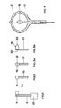
- FIG. 1 shows the construction of a high-pressure discharge lamp 1 with a power consumption of 150 W.
- the lamp 1 consists of a discharge vessel 2 made of quartz glass, which is squeezed on one side and is enclosed by an outer bulb 3 made of quartz glass, which is also squeezed on one side.
- the outer diameter of the lamp is about 25 mm, the total length about 84 mm.
- the discharge vessel 2 has an ellipsoid-like discharge volume with three "axes". The length of the largest "axis”, which is aligned along the connecting line between the tips of the electrodes 4, 5, is approximately 10 mm. The two smaller "axes” that determine the height and width of the discharge volume are approximately the same size (each about 8 mm).
- the electrodes 4, 5 (in a schematic representation) are melted gas-tight into the discharge vessel 2 by means of foils 6, 7 and via the current leads 8, 9, the sealing foils 10, 11 of the outer bulb 3 and via further short current leads 12, 13 with the electrical connections of the ceramic base (not shown) connected.
- a getter material 14 applied to a metal plate is additionally melted potential-free via a piece of wire.
- the discharge vessel 2 As a filling (operating pressure approx. 35 bar), the discharge vessel 2 (with a volume of 0.65 cm3) contains not only mercury (approx. 15 mg) and a noble gas, but also metal iodides and bromides of sodium, tin, thallium, indium and lithium ( a total of 2.3 mg metal halides and an additional 0.2 mg tin).
- the lamp 1 has a luminous efficacy of 83 lm / W at a nominal current of 1.8 A.
- FIG. 2 shows the side view
- FIG. 3 shows the front view of an electrode 4, 5 according to the invention as it is installed in the high-pressure discharge lamp 1 according to FIG. 1.
- It has a straight shaft 15 of 10.2 mm in length made of undoped tungsten wire with a wire diameter of 0.6 mm.
- a cylindrical pin 16 is laterally attached to the discharge-side end of the shaft 15.
- the pin 16 is fastened to the shaft 15 by butt welding, so that the pin 16 and shaft 15 are at right angles to one another.
- the discharge runs transversely to the two shafts 15 arranged parallel to one another.
- the pins 16 are arranged approximately at half the height of the discharge volume, so that a possible influence of the burning position on the operating behavior is minimized.
- a tungsten wire enriched with 0.7% thorium dioxide is used as pin 16.
- An emitter paste is not required.
- the two pins 16 are arranged coaxially to one another and each have a length of 1.2 mm and a diameter of 1.2 mm, the electrode spacing being approximately 6-7 mm (type I version).
- the diameter of the pins 16 is only 0.9 mm with the same length (1.2 mm); the shaft diameter is also somewhat smaller (0.5 mm).
- a sintered body can also be used for the pin, which - pressed from doped tungsten powder - is welded to the end of the shaft.
- Type I When using electrodes with pins with a high heat capacity, the electrode corrosion is significantly reduced.
- the average lifespan of Type I was increased by about 20%, and Type II by about 10% compared to conventional lamps.
- the basic structure largely corresponds to the lamp version shown in FIG. 1 with a higher power level.
- the ellipsoid-like discharge volume has much smaller dimensions, with all three axes having different dimensions: longitudinal axis 5 mm; Transverse axis (width) 4 mm; vertical axis (height) 3.5 mm.
- the filling of the discharge vessel (the has a volume of 0.07 cm3) is similar to the first embodiment, but the bromine is replaced by iodine and an additional excess of tin is introduced.
- This lamp also has similarly improved operating properties as the lamp shown in the first exemplary embodiment.
- FIG. 4 A front view of the electrode used for this lamp is shown in FIG. 4.
- An adaptation to the ellipsoidal discharge vessel 2 ⁇ is achieved here by the elongated, round cross section of the pin.
- the "long side" of the cross-sectional area of the pin has a greater heat radiation than the "transverse side”, which is why the pin on the electrode shaft is oriented so that the "long side” of the pin to the - further away and therefore colder - inner wall in Area of the transverse axis of the discharge vessel 2 ⁇ emits.
- the straight shaft 17 is made of an undoped tungsten wire with a wire diameter of 0.3 mm; it has a length of 6.6 mm.
- the pin 18 (made of 0.7 wt .-% ThO2 enriched tungsten) has a length of 0.7 mm; it has a width of 0.6 mm and a flattened height of 0.55 mm.
- the dimensions shown in FIG. 4 are intended to illustrate the principle and are not to be understood to scale.
- the flattened cross-sectional shape of the pin 18 can be achieved using a wire either by subsequent rolling or already by the shape of the drawing die.
- the molded parts used in the pressing already have a corresponding shape; in general there is also a greater inhomogeneity of the Heat radiation achievable.
- a sintered body 19 is advantageously used in a cone-like shape (or in the form of a pyramid), the sintered body 19 having an ellipsoid-like base 20 (transverse axis d 1) which is welded to the side of the electrode shaft 21 (diameter d 2, where d 2 ⁇ d 1) ;
- the arc discharge begins at the rounded tip 22 of the sintered body 19.
- the area of the base 20 of the cone which projects transversely to the discharge on the shaft 21 then heats up the dead space.
- Fillings with other metals and halides can also be used to achieve different color temperatures and light colors.
- a filling with iodides of sodium and thallium as well as several rare earths (Dy, Ho, Tm) achieves a higher color temperature.
- the exact dimensions of the pin depend on the geometry of the discharge vessel and the power consumption of the lamp. A compromise must be found between the containment of electrode corrosion and good ignitability.
- the composition of the lamp fill is of great importance.
- the electrode dimensions are matched to the filling system used.
Landscapes
- Discharge Lamp (AREA)
- Vessels And Coating Films For Discharge Lamps (AREA)
- Discharge Lamps And Accessories Thereof (AREA)
Applications Claiming Priority (2)
| Application Number | Priority Date | Filing Date | Title |
|---|---|---|---|
| DE3640990 | 1986-12-01 | ||
| DE19863640990 DE3640990A1 (de) | 1986-12-01 | 1986-12-01 | Einseitig gequetschte hochdruckentladungslampe |
Publications (3)
| Publication Number | Publication Date |
|---|---|
| EP0269958A2 true EP0269958A2 (fr) | 1988-06-08 |
| EP0269958A3 EP0269958A3 (en) | 1989-10-11 |
| EP0269958B1 EP0269958B1 (fr) | 1993-02-10 |
Family
ID=6315196
Family Applications (1)
| Application Number | Title | Priority Date | Filing Date |
|---|---|---|---|
| EP87117107A Expired - Lifetime EP0269958B1 (fr) | 1986-12-01 | 1987-11-19 | Lampe à décharge à haute pression munie d'un pincement unique |
Country Status (4)
| Country | Link |
|---|---|
| US (1) | US4937495A (fr) |
| EP (1) | EP0269958B1 (fr) |
| JP (1) | JPS63148530A (fr) |
| DE (2) | DE3640990A1 (fr) |
Cited By (1)
| Publication number | Priority date | Publication date | Assignee | Title |
|---|---|---|---|---|
| EP0381035A2 (fr) * | 1989-01-31 | 1990-08-08 | Toshiba Lighting & Technology Corporation | Lampe à décharge à vapeur métallique à scellement unique |
Families Citing this family (8)
| Publication number | Priority date | Publication date | Assignee | Title |
|---|---|---|---|---|
| US4998036A (en) * | 1987-12-17 | 1991-03-05 | Kabushiki Kaisha Toshiba | Metal vapor discharge lamp containing an arc tube with particular bulb structure |
| JP2668434B2 (ja) * | 1989-01-31 | 1997-10-27 | 東芝ライテック株式会社 | メタルハライドランプ |
| NL9500350A (nl) * | 1994-02-25 | 1995-10-02 | Ushio Electric Inc | Metaalhalogenidelamp met een eendelige opstelling van een frontafdekking en een reflector. |
| JP3211654B2 (ja) * | 1996-03-14 | 2001-09-25 | 松下電器産業株式会社 | 高圧放電ランプ |
| JP3596453B2 (ja) * | 2000-09-28 | 2004-12-02 | ウシオ電機株式会社 | ショートアーク放電ランプ |
| DE10318051A1 (de) * | 2003-04-17 | 2004-11-04 | Patent-Treuhand-Gesellschaft für elektrische Glühlampen mbH | Halogenglühlampe |
| DE102007061514A1 (de) * | 2007-12-20 | 2009-06-25 | Osram Gesellschaft mit beschränkter Haftung | Elektrode für eine Hochdruckentladungslampe und Verfahren zu ihrer Fertigung |
| KR101500092B1 (ko) | 2013-06-26 | 2015-03-06 | 현대자동차주식회사 | 운전자의 수동적 과업 관련 피로 방지 장치 및 그 방법 |
Citations (2)
| Publication number | Priority date | Publication date | Assignee | Title |
|---|---|---|---|---|
| GB2072412A (en) * | 1980-03-24 | 1981-09-30 | Gte Prod Corp | Electrode geometry to improve arc stability |
| GB2126415A (en) * | 1982-08-30 | 1984-03-21 | Patent Treuhand Ges Fuer Elektrische Gluehlampen Mbh | Discharge lamp |
Family Cites Families (11)
| Publication number | Priority date | Publication date | Assignee | Title |
|---|---|---|---|---|
| US1655488A (en) * | 1925-03-18 | 1928-01-10 | Gen Electric | Electric incandescent lamp |
| GB476833A (en) * | 1936-09-25 | 1937-12-16 | Patent Treuhand Ges Fuer Elektrische Gluehlampen Mbh | Improvements in or relating to high-pressure metal-vapour electric discharge lamps |
| US2459579A (en) * | 1947-08-06 | 1949-01-18 | Gen Electric | Electrode structure |
| US2662196A (en) * | 1948-11-04 | 1953-12-08 | Western Union Telegraph Co | Concentrated arc lamp |
| US2697183A (en) * | 1950-10-16 | 1954-12-14 | Patent Treuhand Ges Fuer Elektrische Gluehlampen Mbh | High-pressure electric discharge lamp |
| FR1126531A (fr) * | 1955-05-13 | 1956-11-26 | Cie Ind De Tubes Et Lampes Ele | Perfectionnements aux appareils dits parafoudres à gaz, ou parasurtensions, ou limiteurs de tension |
| US3625068A (en) * | 1970-08-31 | 1971-12-07 | Gen Motors Corp | Omnidirectional sensor |
| NL7300381A (fr) * | 1973-01-11 | 1974-07-15 | ||
| JPS5211677A (en) * | 1975-07-17 | 1977-01-28 | Iwasaki Electric Co Ltd | Discharge lamp with sintered electrode |
| US4633136A (en) * | 1982-04-20 | 1986-12-30 | Patent-Treuhand-Gesellschaft Fur Elektrische Gluhlampen Mbh | High-pressure discharge lamp with low power input |
| DD242736A3 (de) * | 1983-03-25 | 1987-02-11 | Narva Rosa Luxemburg Bgw K Veb | Elektroden fuer elektrische entladungslampen, vorzugsweise hochdruckentladungslampen kleiner leistung |
-
1986
- 1986-12-01 DE DE19863640990 patent/DE3640990A1/de not_active Withdrawn
-
1987
- 1987-11-19 DE DE8787117107T patent/DE3784144D1/de not_active Expired - Fee Related
- 1987-11-19 EP EP87117107A patent/EP0269958B1/fr not_active Expired - Lifetime
- 1987-11-30 JP JP62300331A patent/JPS63148530A/ja active Granted
-
1989
- 1989-01-13 US US07/298,271 patent/US4937495A/en not_active Expired - Fee Related
Patent Citations (2)
| Publication number | Priority date | Publication date | Assignee | Title |
|---|---|---|---|---|
| GB2072412A (en) * | 1980-03-24 | 1981-09-30 | Gte Prod Corp | Electrode geometry to improve arc stability |
| GB2126415A (en) * | 1982-08-30 | 1984-03-21 | Patent Treuhand Ges Fuer Elektrische Gluehlampen Mbh | Discharge lamp |
Cited By (2)
| Publication number | Priority date | Publication date | Assignee | Title |
|---|---|---|---|---|
| EP0381035A2 (fr) * | 1989-01-31 | 1990-08-08 | Toshiba Lighting & Technology Corporation | Lampe à décharge à vapeur métallique à scellement unique |
| EP0381035A3 (fr) * | 1989-01-31 | 1991-06-05 | Toshiba Lighting & Technology Corporation | Lampe à décharge à vapeur métallique à scellement unique |
Also Published As
| Publication number | Publication date |
|---|---|
| EP0269958A3 (en) | 1989-10-11 |
| JPH0584630B2 (fr) | 1993-12-02 |
| DE3640990A1 (de) | 1988-06-16 |
| JPS63148530A (ja) | 1988-06-21 |
| DE3784144D1 (de) | 1993-03-25 |
| EP0269958B1 (fr) | 1993-02-10 |
| US4937495A (en) | 1990-06-26 |
Similar Documents
| Publication | Publication Date | Title |
|---|---|---|
| EP0834905B1 (fr) | Lampe haute pression au sodium de faible puissance | |
| DE3716485C1 (de) | Xenon-Kurzbogen-Entladungslampe | |
| EP0453893B1 (fr) | Lampe à décharge à haute pression | |
| DE69825700T2 (de) | Metallhalogenidlampe | |
| DE2718642C2 (de) | Elektrode für eine Hochdruck-Metallhalogenidlampe | |
| EP0092221B1 (fr) | Lampe à décharge à haute pression de bas pouvoir | |
| EP0602529A2 (fr) | Lampe de décharge à haute pression ayant un récipient céramique de décharge | |
| EP0269958B1 (fr) | Lampe à décharge à haute pression munie d'un pincement unique | |
| DE69926445T2 (de) | Hochdruck-Entladungslampe | |
| DE3038993C2 (de) | Metalldampfentladungslampe | |
| EP0269957B1 (fr) | Lampe à décharge à haute pression munie d'un pincement unique | |
| WO2008074361A1 (fr) | Électrode pour une lampe à décharge | |
| DE2627380C3 (de) | Metalldampf-Hochdruckentladungslampe für horizontalen Betrieb | |
| EP0456907B1 (fr) | Lampe à décharge à haute pression | |
| DE2131887C3 (de) | Blitzentladungslampe | |
| DE2422576B2 (de) | Quecksilberdampflampe | |
| DE3044121C2 (de) | Natriumhochdrucklampe | |
| DE2753898A1 (de) | Hochintensive entladungslampe | |
| DE976223C (de) | Elektrische Hochdruck-Gasentladungslampe fuer Gleichstrombetrieb mit festen Gluehelektroden | |
| DE1489406B2 (de) | Hochdruck-quecksilberdampfentladungslampe | |
| EP1709668B1 (fr) | Lampe a decharge basse pression | |
| EP1255279B1 (fr) | Lampe incandescente à halogène | |
| DE3242840C2 (fr) | ||
| DE4203976A1 (de) | Hochdruckentladungslampe | |
| DE2535031C3 (de) | Zündelektrode für Hochdruck-Entladungslampen |
Legal Events
| Date | Code | Title | Description |
|---|---|---|---|
| PUAI | Public reference made under article 153(3) epc to a published international application that has entered the european phase |
Free format text: ORIGINAL CODE: 0009012 |
|
| AK | Designated contracting states |
Kind code of ref document: A2 Designated state(s): DE FR GB IT |
|
| RAP3 | Party data changed (applicant data changed or rights of an application transferred) |
Owner name: PATENT-TREUHAND-GESELLSCHAFT FUER ELEKTRISCHE GLUE |
|
| PUAL | Search report despatched |
Free format text: ORIGINAL CODE: 0009013 |
|
| AK | Designated contracting states |
Kind code of ref document: A3 Designated state(s): DE FR GB IT |
|
| 17P | Request for examination filed |
Effective date: 19891026 |
|
| 17Q | First examination report despatched |
Effective date: 19910829 |
|
| GRAA | (expected) grant |
Free format text: ORIGINAL CODE: 0009210 |
|
| AK | Designated contracting states |
Kind code of ref document: B1 Designated state(s): DE FR GB IT |
|
| REF | Corresponds to: |
Ref document number: 3784144 Country of ref document: DE Date of ref document: 19930325 |
|
| ET | Fr: translation filed | ||
| ITF | It: translation for a ep patent filed |
Owner name: STUDIO JAUMANN |
|
| GBT | Gb: translation of ep patent filed (gb section 77(6)(a)/1977) |
Effective date: 19930416 |
|
| PLBE | No opposition filed within time limit |
Free format text: ORIGINAL CODE: 0009261 |
|
| STAA | Information on the status of an ep patent application or granted ep patent |
Free format text: STATUS: NO OPPOSITION FILED WITHIN TIME LIMIT |
|
| PGFP | Annual fee paid to national office [announced via postgrant information from national office to epo] |
Ref country code: DE Payment date: 19940119 Year of fee payment: 7 |
|
| 26N | No opposition filed | ||
| PGFP | Annual fee paid to national office [announced via postgrant information from national office to epo] |
Ref country code: GB Payment date: 19941018 Year of fee payment: 8 |
|
| PGFP | Annual fee paid to national office [announced via postgrant information from national office to epo] |
Ref country code: FR Payment date: 19941117 Year of fee payment: 8 |
|
| PG25 | Lapsed in a contracting state [announced via postgrant information from national office to epo] |
Ref country code: DE Effective date: 19950801 |
|
| PG25 | Lapsed in a contracting state [announced via postgrant information from national office to epo] |
Ref country code: GB Effective date: 19951119 |
|
| GBPC | Gb: european patent ceased through non-payment of renewal fee |
Effective date: 19951119 |
|
| PG25 | Lapsed in a contracting state [announced via postgrant information from national office to epo] |
Ref country code: FR Effective date: 19960731 |
|
| REG | Reference to a national code |
Ref country code: FR Ref legal event code: ST |
|
| PG25 | Lapsed in a contracting state [announced via postgrant information from national office to epo] |
Ref country code: IT Free format text: LAPSE BECAUSE OF NON-PAYMENT OF DUE FEES;WARNING: LAPSES OF ITALIAN PATENTS WITH EFFECTIVE DATE BEFORE 2007 MAY HAVE OCCURRED AT ANY TIME BEFORE 2007. THE CORRECT EFFECTIVE DATE MAY BE DIFFERENT FROM THE ONE RECORDED. Effective date: 20051119 |