EP0268761B1 - Filtre pour liquides, en particulier pour combustibles - Google Patents
Filtre pour liquides, en particulier pour combustibles Download PDFInfo
- Publication number
- EP0268761B1 EP0268761B1 EP87112922A EP87112922A EP0268761B1 EP 0268761 B1 EP0268761 B1 EP 0268761B1 EP 87112922 A EP87112922 A EP 87112922A EP 87112922 A EP87112922 A EP 87112922A EP 0268761 B1 EP0268761 B1 EP 0268761B1
- Authority
- EP
- European Patent Office
- Prior art keywords
- filter
- distance rings
- rings
- distance
- casing
- Prior art date
- Legal status (The legal status is an assumption and is not a legal conclusion. Google has not performed a legal analysis and makes no representation as to the accuracy of the status listed.)
- Expired - Lifetime
Links
Images

Classifications
-
- B—PERFORMING OPERATIONS; TRANSPORTING
- B01—PHYSICAL OR CHEMICAL PROCESSES OR APPARATUS IN GENERAL
- B01D—SEPARATION
- B01D25/00—Filters formed by clamping together several filtering elements or parts of such elements
- B01D25/22—Cell-type filters
- B01D25/26—Cell-type stack filters
Definitions
- the invention relates to a liquid filter according to the preamble of the main claim.
- a liquid filter is already known from DE-A-17 61 498, in which a filter insert is arranged in a housing and consists of circular filter disks, outer and inner spacer disks and support disks.
- the outer spacers are designed here as profiled rings, which fork at their outer end and are specially shaped for support in a profile seal, openings being provided for the flow of liquid in the bent-up edges.
- the inner spacer is constructed more as a solid ring, so that the spacers have components of different types.
- a relatively complex U-shaped rubber profile seal is provided, which engages around the outer edges of two support disks.
- the axial contact pressure for the stacked disks is generated by an expensive screw connection, for which an additional inner support tube is required.
- this filter insert there is advantageously no expensive and time-consuming gluing process necessary, but this filter insert has the disadvantage that it is extremely complex and therefore expensive. The large number of components also complicates the manufacture of the filter.
- a liquid filter is known from DE-A-748 206, in which the filter insert is constructed in the manner of a cell filter.
- a flat, flat filter paper disk is arranged between two adjacent guide disks, which each consist of two rings running concentrically to one another and connected to one another by webs.
- One adjacent guide disk in the outer ring and the other adjacent guide disk in the inner ring each have openings so that the filter paper disk can be flowed through axially.
- this filter insert has the disadvantage that the flat filter paper disc at the points where it spans the openings of the adjacent guide discs can be deformed as a result of sources in operation or by deformation so that leak connections from the dirt to the clean side arise.
- Another disadvantage is that valuable filter area is lost due to the webs. Since the number of breakthroughs in the guide disks is to be limited by the risk of leakage, the flow resistance of the filter insert is relatively high. The perforated guide discs also require increased caution when installing them.
- GB-A-717 656 uses additional screw connections for clamping the filter disks, with spacing rings that mutually centering on the one hand and centering on the other hand.
- the liquid filter according to the invention with the characterizing features of the main claim has the advantage that it allows a design without the use of adhesive, allows an optimal filter surface and is inexpensive to manufacture.
- the filter insert can be manufactured using environmentally friendly manufacturing processes, whereby special soft seals are not required.
- the filter insert Due to the design of the filter insert, no additional inner or outer support tubes are required; the necessary axial contact pressure can be achieved by simple spring elements.
- the filter is particularly suitable for cost-reducing mass production.
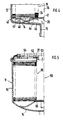
- FIG. 1 shows a longitudinal section through half of a first liquid filter
- FIG. 2 shows a plan view of part of an outer spacer ring on an enlarged scale
- FIG. 3 shows a section according to III-III in FIG. 2
- FIG. 4 shows a partial longitudinal section through a second liquid filter
- FIG 5 shows a longitudinal section through half of a third liquid filter in a box design.
- FIG. 1 shows a liquid filter 10, the housing 11 of which consists of aluminum and consists of a cup-shaped housing pot 12 and a housing cover 13.
- a central inlet opening 15 for an inlet and support ribs 16 projecting into the housing interior are arranged on a bottom 14 of the housing pot 12.
- the housing 11 accommodates in its interior a filter insert 19 which is constructed in the manner of a cell filter.
- the filter insert consists of a filter disk package 21, which consists in particular of a plurality of ring-shaped, flat filter disks 22, of outer spacer rings 23 and of inner spacer rings 24, which are stacked one above the other and arranged between a rigid lower end plate 25 and a rigid upper end plate 26 are.
- the spacer ring 23 has two flat and smooth contact surfaces 27, 28 lying on opposite sides. Between these contact surfaces 27, 28 run hole-like passages 29 which pass through the pressure medium flow and which are rectangular in cross section and which run essentially radially. In this way, the contact surfaces 27 and 28 are formed along the entire circumference of the spacer ring 23 without interruption and continuously with a smooth surface.
- the cross section of the outer spacer ring 23 has a rectangular shape, the width of which is approximately twice as large as its thickness.
- the free cross section of the hole-like passages 29 is suitably chosen so large that in the filter insert 19 occurring axial pressure, the flat contact surfaces 27, 28 do not significantly deform and thus a perfect seal between the dirt side and the clean side remains.
- radially outwardly projecting lugs 31 are formed, which center the filter disk package 21 in the housing pot 12 and at the same time pressure medium channels form, via which the fuel to be cleaned can flow to the passages 29, which are open to a lateral surface 32 of the filter insert 19.
- the inner spacer rings 24 are constructed in the same way as the outer spacer rings 23, only have a smaller diameter and do not require lugs 31 for spacing.
- the filter disks 22 are annular, consist of a suitable filter paper and are stacked with the spacer rings 23, 24 so that the edges on the inner and outer periphery of two adjacent filter disks either lie directly against one another or accommodate a spacer ring between them.
- cells 33 which are assigned to the dirt side 15, are formed in the filter insert 19 via the outer spacer rings 23 toward the lateral surface 32.
- intermediate cells 34 are thereby formed, which are connected via the inner spacer rings 24 to a centrally located drain channel 35 and further to the connecting piece 18 for the drain.
- the filter disks 22 with the spacer rings 23, 24 between the rigid end plates 25 and 26 are compressed so strongly after the stacking that there is a tight and sufficiently firm connection between the individual filter disks 22 and spacer rings 23, 24, so that the filter disk package 21 forms a self-supporting component without any addition of adhesive. Due to the stable against pressure Spacer rings 23, 24 with their continuously smooth contact surfaces 27, 28 make such a connection possible without this causing disturbing deformations which could lead to leak connections between the dirty and clean side.
- the filter insert 19 can therefore be produced in a very environmentally friendly manner.
- the spacer rings 23, 24 can consist of paper, plastic or another suitable material. Another suitable, thin-walled filter material can also be used for the filter discs instead of the filter paper.
- the filter insert 19 is clamped in the housing 11 with sufficient axial contact pressure. It rests with its lower, rigid end plate 25 on the supporting ribs 16, while the upper rigid end plate 26 is supported in the housing 11 by means of a molded pipe socket 36 and an associated sealing ring 37.
- the mode of operation of the liquid filter 10 is similar to that of conventional cell filters.
- the fuel to be cleaned flowing in via the connecting piece 15 flows between the support ribs 16 into the annular space existing between the inner wall of the housing pot 12 and the outer surface 32 of the filter insert 19.
- the fuel Via the radial passages 29 in the outer spacer rings 23, the fuel reaches the cells 33 assigned to the dirt side. It then flows axially through the filter disks 22 into the cells 34 and reaches the discharge channel 35 and through the passages 29 in the inner spacer rings 24 continue to the connector 18 for the drain.
- Numerous passages 29 in the outer and inner spacer rings 23, 24 keep the flow resistance relatively low. Due to the filter paper disks 22 extending freely between the outer and inner spacer rings 23, 24 the size of the effective filter area can be optimally designed and at the same time the overall flow resistance can be kept low.
- FIG. 4 shows a partial longitudinal section through a second liquid filter 40, which differs from the first liquid filter 10 according to FIG. 1 as follows, the same reference numerals being used for the same components.
- the rigid lower end plate 25 is divided into two and consists of a centrally arranged plate 41 and an outer ring 42 arranged in the same radial plane.
- the plate 41 lies against the inner spacer rings 24 and at the same time blocks the drainage channel 35 from the dirt side in the Inlet opening 15 for the inlet.
- the bottom 14 in the housing pot 12 has no support ribs, so that a first ring spring 43 resting against it with its arms 44 axially loads the plate 41 in the area of the inner spacer rings 24.
- a second ring spring 45 resting on the bottom 14 presses the outer ring 42 with its spring arms 46 in the axial direction against the outer spacer rings 23.
- the two ring springs 43, 45 thus ensure a sufficient axial contact pressure of the filter insert 19 in the housing 11 and also enable a sufficient flow cross-section for the inflowing fuel flow.
- FIG. 5 shows a longitudinal section through half of a third liquid filter 50, which differs from the first liquid filter 10 in line filter type primarily in its design as a filter box. Otherwise, the same components as in Figure 1 are given the same reference numerals.
- the housing 11 consists of a closed, cup-shaped housing pot 51 and an associated housing cover 52, in which, in addition to the centrally located connecting piece 53, a plurality of openings 54 for the drain in a manner known per se are arranged for the supply of fuel.
- the identical filter insert 19 is pressed axially against the sealing ring 37 by a spring washer supported on the base 14.
- the mode of operation of the liquid filter 50 with regard to the filter insert 19 designed as a cell filter corresponds to that of the first liquid filter 10.
- the filter insert 19 shown in FIGS. 1 and 5 represents a particularly advantageous combination of construction features, since it enables a filter insert that is simple and inexpensive to manufacture and handle, in which the risk of leak connections between the dirty and clean side due to the swelling adhesive connection is particularly strong with aggressive fuels is reduced.
- the advantageous design of the filter insert as a self-supporting structure without the use of adhesive is also possible if, instead of the circular shape, the circumferential shape of a polygon is chosen, the number of corners in particular being four to eight.
- the design of the filter insert 19 according to the invention can also be used in various housing designs. Instead of the aluminum housing used, a plastic housing could be used, the edges of which, e.g. be welded by ultrasound.
- a one-part ring spring can also be used, which e.g. has a total of eight resilient arms, four of which are bent up with their inner end and the other four arms with their outer end so that they resiliently support the filter insert.
Landscapes
- Chemical & Material Sciences (AREA)
- Chemical Kinetics & Catalysis (AREA)
- Filtration Of Liquid (AREA)
- Lubrication Details And Ventilation Of Internal Combustion Engines (AREA)
Claims (7)
- Filtre pour liquides, notamment pour combustibles, avec une partie opérationnelle de filtre (19) disposée dans un carter (11), dans laquelle des disques de filtration individuels (22) sont assemblés à la façon d'un filtre cellulaire par empilage en interposant alternativement un anneau externe d'écartement (23) ou un anneau interne d'écartement (24), et dans laquelle des plaques terminales rigides (25, 26) sont placées aux deux extrémités du paquet de disques de filtration, tandis que sur la surface enveloppe externe (32) du paquet de disques de filtration se trouvent plusieurs passages (29) communiquant avec une ouverture d'arrivée (15), qui à travers les disques de filtration (22) et les anneaux internes d'écartement (24) communiquent avec un canal central d'évacuation (35) débouchant dans une ouverture d'évacuation (18), et avec un dispositif maintenant ensemble en direction axiale les disques de filtration (22) et les disques d'écartement (23, 24), tandis que dans ces anneaux d'écartement (23, 24) les côtés opposés l'un à l'autre comportent deux surfaces d'appui (27, 28) s'étendant en continu avec des surfaces lisses et que les passages (29) sont en forme de trous, et les anneaux externes d'écartement (23) et les anneaux internes d'écartement (24) ont la même épaisseur et les disques de filtration (22) en matériau de filtration à paroi mince sont serrés par leurs bords externe et interne sans être soutenus entre les anneaux d'écartement externes et internes (23, 24), filtre pour liquides caractérisé en ce que les anneaux d'écartement internes et externes (23, 24) comportent respectivement une section transversale rectangulaire dont les côtés les plus longs sont associés aux surfaces d'appui (27, 28), en ce que les anneaux d'écartement (23, 24) sont constitués par un matériau non métallique, et en ce que le paquet de disques de filtration est réalisé sous la forme d'un élément de construction auto-porteur, ne comportant pas de tubes de support externe ou interne, et dont la cohésion est maintenue par la pression d'assemblage des disques de filtration (22) et des anneaux d'écartement (23, 24).
- Filtre pour liquides selon la revendication 1, caractérisé en ce que des taquets (31) faisant saillie radialement vers l'extérieur sont disposés latéralement à côté des passages (29) sur les anneaux externes d'écartement (23), et maintiennent la surface enveloppe (32) à une certaine distance de la paroi interne du carter (11).
- Filtre pour liquides selon la revendication 1 ou la revendication 2, caractérisé en ce que la largeur des anneaux d'écartement (23, 24) en direction radiale, est d'environ le double de l'épaisseur de ces anneaux d'écartement (23, 24) en direction axiale.
- Filtre pour liquides selon une ou plusieurs des revendications 1 à 3, caractérisé en ce que les disques de filtration (22) et les anneaux d'écartement (23, 24) sont de forme circulaire et sont notamment en papier.
- Filtre pour liquides selon une ou plusieurs des revendications 1 à 4, caractérisé en ce que les disques de filtration et les anneaux externes d'écartement, ont à leurs périphéries la forme d'un polygone régulier dont le nombre de côtés se situe notamment entre quatre et huit.
- Filtre pour liquides selon une ou plusieurs des revendications 1 à 5, avec un carter (11) constitué par un pot de carter (12) et un couvercle de carter (13), caractérisé en ce qu'un élément élastique (43, 44; 55) s'appliquant sur le fond (14) du pot (12, 51) du carter, presse de façon étanche la partie opérationnelle du filtre (19) avec sa plaque terminale supérieure rigide (26) contre le couvercle (13; 52) du carter.
- Filtre pour liquides selon une des revendications 1 à 6, caractérisé en ce que les anneaux d'écartement internes (24), empilés les uns sur les autres, constituent un tube médian perforé formant le canal d'évacuation (35).
Applications Claiming Priority (2)
| Application Number | Priority Date | Filing Date | Title |
|---|---|---|---|
| DE19863635728 DE3635728A1 (de) | 1986-10-21 | 1986-10-21 | Fluessigkeitsfilter, insbesondere fuer kraftstoffe |
| DE3635728 | 1986-10-21 |
Publications (3)
| Publication Number | Publication Date |
|---|---|
| EP0268761A2 EP0268761A2 (fr) | 1988-06-01 |
| EP0268761A3 EP0268761A3 (en) | 1988-11-09 |
| EP0268761B1 true EP0268761B1 (fr) | 1992-06-03 |
Family
ID=6312123
Family Applications (1)
| Application Number | Title | Priority Date | Filing Date |
|---|---|---|---|
| EP87112922A Expired - Lifetime EP0268761B1 (fr) | 1986-10-21 | 1987-09-04 | Filtre pour liquides, en particulier pour combustibles |
Country Status (3)
| Country | Link |
|---|---|
| EP (1) | EP0268761B1 (fr) |
| JP (1) | JPS63104623A (fr) |
| DE (2) | DE3635728A1 (fr) |
Families Citing this family (4)
| Publication number | Priority date | Publication date | Assignee | Title |
|---|---|---|---|---|
| US5271838A (en) * | 1991-09-13 | 1993-12-21 | Pall Corporation | Filter assembly with filter elements separated by spacers |
| DE4417298A1 (de) * | 1994-05-18 | 1995-11-23 | Knecht Filterwerke Gmbh | Rohrförmiger Stützkörper für einen ringförmigen Filtereinsatz |
| US6595371B1 (en) * | 2002-02-28 | 2003-07-22 | Arvin Technologies, Inc. | Fluid filter assembly |
| DE10262133B4 (de) * | 2002-08-02 | 2007-11-29 | Mahle Filtersysteme Gmbh | Randdichtung eines Filterelementes mit im wesentlichen plattenförmig angeordnetem Filtermaterial |
Family Cites Families (6)
| Publication number | Priority date | Publication date | Assignee | Title |
|---|---|---|---|---|
| US2143270A (en) * | 1936-08-13 | 1939-01-10 | Tuthill Pump Co | Strainer |
| DE715197C (de) * | 1938-07-24 | 1941-12-16 | Fritz Faudi | Stuetzringe zum Festlegen der Filtermittel und zur Fuehrung der Fluessigkeit in Filtervorrichtungen mit stockwerkartig uebereinander angeordneten Filterkammern |
| FR1017959A (fr) * | 1950-05-16 | 1952-12-24 | Cartouche filtrante à anneaux élastiques | |
| BE505358A (fr) * | 1950-09-09 | 1900-01-01 | ||
| DE166151C (fr) * | 1952-02-23 | 1900-01-01 | ||
| JPS5820288B2 (ja) * | 1978-04-20 | 1983-04-22 | 日本建鐵株式会社 | 加圧「ろ」過機 |
-
1986
- 1986-10-21 DE DE19863635728 patent/DE3635728A1/de not_active Withdrawn
-
1987
- 1987-09-04 DE DE8787112922T patent/DE3779572D1/de not_active Expired - Lifetime
- 1987-09-04 EP EP87112922A patent/EP0268761B1/fr not_active Expired - Lifetime
- 1987-10-16 JP JP62259861A patent/JPS63104623A/ja active Pending
Also Published As
| Publication number | Publication date |
|---|---|
| EP0268761A3 (en) | 1988-11-09 |
| EP0268761A2 (fr) | 1988-06-01 |
| DE3779572D1 (de) | 1992-07-09 |
| DE3635728A1 (de) | 1988-04-28 |
| JPS63104623A (ja) | 1988-05-10 |
Similar Documents
| Publication | Publication Date | Title |
|---|---|---|
| DE60133449T2 (de) | Fluidfilter und ein Fluidfilter-Filterkopf-Gerät | |
| EP0155458B1 (fr) | Plaque de membrane filtrante | |
| WO1990006799A1 (fr) | Filtre a huile pour moteurs a combustion interne | |
| EP1104331A1 (fr) | Module filtrant | |
| DE102010047491A1 (de) | Filtereinsatz und Filtervorrichtung | |
| DE19520156A1 (de) | Filter, insbesondere Luftfilter für die Ansaugluft einer Brennkraftmaschine | |
| EP1736227A1 (fr) | Système d'étanchéité d'un filtre | |
| EP1024874A1 (fr) | Support annulaire dote d'une pince destinee aux extremites d'un papier en accordeon | |
| DE102016002246A1 (de) | Filterelement, insbesondere zur Gasfiltration | |
| DE2856434A1 (de) | Wegwerf-filter, insbesondere oelfiltereinsatz | |
| DE3341361C2 (de) | Radiator, insbesondere für Klimaanlagen von Kraftfahrzeugen | |
| DE102008062952A1 (de) | Filterelement in einem Kraftstofffilter | |
| DE102014007373A1 (de) | Faltenförmiges Filterelement | |
| EP0268761B1 (fr) | Filtre pour liquides, en particulier pour combustibles | |
| EP0492130B1 (fr) | Echangeur de chaleur | |
| DE905970C (de) | Filterkartusche | |
| DE3329525C2 (fr) | ||
| EP0528179B1 (fr) | Filtre à liquides | |
| DE19848978B4 (de) | Filterelement | |
| EP0191160B1 (fr) | Arrangement d'étanchéité | |
| DE19829233A1 (de) | Hydraulisch dämpfendes Motorlager | |
| DE3239687A1 (de) | Filtrationsvorrichtung | |
| DE3200443A1 (de) | Filtrationsgeraet fuer flachfilterzuschnitte | |
| EP0775513A2 (fr) | Filtre de liquide avec un échangeur de chaleur d'un empilage de disques | |
| DE2020057C3 (de) | Kreiszylinderförmiges Filter, insbesondere ölfilter für Hydraulikanlagen |
Legal Events
| Date | Code | Title | Description |
|---|---|---|---|
| PUAI | Public reference made under article 153(3) epc to a published international application that has entered the european phase |
Free format text: ORIGINAL CODE: 0009012 |
|
| AK | Designated contracting states |
Kind code of ref document: A2 Designated state(s): DE FR GB IT |
|
| PUAL | Search report despatched |
Free format text: ORIGINAL CODE: 0009013 |
|
| AK | Designated contracting states |
Kind code of ref document: A3 Designated state(s): DE FR GB IT |
|
| 17P | Request for examination filed |
Effective date: 19890505 |
|
| 17Q | First examination report despatched |
Effective date: 19901211 |
|
| RAP3 | Party data changed (applicant data changed or rights of an application transferred) |
Owner name: ROBERT BOSCH GMBH |
|
| GRAA | (expected) grant |
Free format text: ORIGINAL CODE: 0009210 |
|
| AK | Designated contracting states |
Kind code of ref document: B1 Designated state(s): DE FR GB IT |
|
| GBT | Gb: translation of ep patent filed (gb section 77(6)(a)/1977) | ||
| REF | Corresponds to: |
Ref document number: 3779572 Country of ref document: DE Date of ref document: 19920709 |
|
| ET | Fr: translation filed | ||
| ITF | It: translation for a ep patent filed |
Owner name: STUDIO JAUMANN |
|
| PLBE | No opposition filed within time limit |
Free format text: ORIGINAL CODE: 0009261 |
|
| STAA | Information on the status of an ep patent application or granted ep patent |
Free format text: STATUS: NO OPPOSITION FILED WITHIN TIME LIMIT |
|
| 26N | No opposition filed | ||
| PGFP | Annual fee paid to national office [announced via postgrant information from national office to epo] |
Ref country code: GB Payment date: 19940825 Year of fee payment: 8 |
|
| PGFP | Annual fee paid to national office [announced via postgrant information from national office to epo] |
Ref country code: FR Payment date: 19940930 Year of fee payment: 8 |
|
| PG25 | Lapsed in a contracting state [announced via postgrant information from national office to epo] |
Ref country code: GB Effective date: 19950904 |
|
| GBPC | Gb: european patent ceased through non-payment of renewal fee |
Effective date: 19950904 |
|
| PG25 | Lapsed in a contracting state [announced via postgrant information from national office to epo] |
Ref country code: FR Effective date: 19960531 |
|
| REG | Reference to a national code |
Ref country code: FR Ref legal event code: ST |
|
| PGFP | Annual fee paid to national office [announced via postgrant information from national office to epo] |
Ref country code: DE Payment date: 19981130 Year of fee payment: 12 |
|
| PG25 | Lapsed in a contracting state [announced via postgrant information from national office to epo] |
Ref country code: DE Free format text: LAPSE BECAUSE OF NON-PAYMENT OF DUE FEES Effective date: 20000701 |
|
| PG25 | Lapsed in a contracting state [announced via postgrant information from national office to epo] |
Ref country code: IT Free format text: LAPSE BECAUSE OF NON-PAYMENT OF DUE FEES;WARNING: LAPSES OF ITALIAN PATENTS WITH EFFECTIVE DATE BEFORE 2007 MAY HAVE OCCURRED AT ANY TIME BEFORE 2007. THE CORRECT EFFECTIVE DATE MAY BE DIFFERENT FROM THE ONE RECORDED. Effective date: 20050904 |