EP0268761B1 - Liquid filter, especially for motor fuels - Google Patents
Liquid filter, especially for motor fuels Download PDFInfo
- Publication number
- EP0268761B1 EP0268761B1 EP87112922A EP87112922A EP0268761B1 EP 0268761 B1 EP0268761 B1 EP 0268761B1 EP 87112922 A EP87112922 A EP 87112922A EP 87112922 A EP87112922 A EP 87112922A EP 0268761 B1 EP0268761 B1 EP 0268761B1
- Authority
- EP
- European Patent Office
- Prior art keywords
- filter
- distance rings
- rings
- distance
- casing
- Prior art date
- Legal status (The legal status is an assumption and is not a legal conclusion. Google has not performed a legal analysis and makes no representation as to the accuracy of the status listed.)
- Expired - Lifetime
Links
Images

Classifications
-
- B—PERFORMING OPERATIONS; TRANSPORTING
- B01—PHYSICAL OR CHEMICAL PROCESSES OR APPARATUS IN GENERAL
- B01D—SEPARATION
- B01D25/00—Filters formed by clamping together several filtering elements or parts of such elements
- B01D25/22—Cell-type filters
- B01D25/26—Cell-type stack filters
Definitions
- the invention relates to a liquid filter according to the preamble of the main claim.
- a liquid filter is already known from DE-A-17 61 498, in which a filter insert is arranged in a housing and consists of circular filter disks, outer and inner spacer disks and support disks.
- the outer spacers are designed here as profiled rings, which fork at their outer end and are specially shaped for support in a profile seal, openings being provided for the flow of liquid in the bent-up edges.
- the inner spacer is constructed more as a solid ring, so that the spacers have components of different types.
- a relatively complex U-shaped rubber profile seal is provided, which engages around the outer edges of two support disks.
- the axial contact pressure for the stacked disks is generated by an expensive screw connection, for which an additional inner support tube is required.
- this filter insert there is advantageously no expensive and time-consuming gluing process necessary, but this filter insert has the disadvantage that it is extremely complex and therefore expensive. The large number of components also complicates the manufacture of the filter.
- a liquid filter is known from DE-A-748 206, in which the filter insert is constructed in the manner of a cell filter.
- a flat, flat filter paper disk is arranged between two adjacent guide disks, which each consist of two rings running concentrically to one another and connected to one another by webs.
- One adjacent guide disk in the outer ring and the other adjacent guide disk in the inner ring each have openings so that the filter paper disk can be flowed through axially.
- this filter insert has the disadvantage that the flat filter paper disc at the points where it spans the openings of the adjacent guide discs can be deformed as a result of sources in operation or by deformation so that leak connections from the dirt to the clean side arise.
- Another disadvantage is that valuable filter area is lost due to the webs. Since the number of breakthroughs in the guide disks is to be limited by the risk of leakage, the flow resistance of the filter insert is relatively high. The perforated guide discs also require increased caution when installing them.
- GB-A-717 656 uses additional screw connections for clamping the filter disks, with spacing rings that mutually centering on the one hand and centering on the other hand.
- the liquid filter according to the invention with the characterizing features of the main claim has the advantage that it allows a design without the use of adhesive, allows an optimal filter surface and is inexpensive to manufacture.
- the filter insert can be manufactured using environmentally friendly manufacturing processes, whereby special soft seals are not required.
- the filter insert Due to the design of the filter insert, no additional inner or outer support tubes are required; the necessary axial contact pressure can be achieved by simple spring elements.
- the filter is particularly suitable for cost-reducing mass production.
- FIG. 1 shows a longitudinal section through half of a first liquid filter
- FIG. 2 shows a plan view of part of an outer spacer ring on an enlarged scale
- FIG. 3 shows a section according to III-III in FIG. 2
- FIG. 4 shows a partial longitudinal section through a second liquid filter
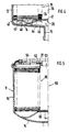
- FIG 5 shows a longitudinal section through half of a third liquid filter in a box design.
- FIG. 1 shows a liquid filter 10, the housing 11 of which consists of aluminum and consists of a cup-shaped housing pot 12 and a housing cover 13.
- a central inlet opening 15 for an inlet and support ribs 16 projecting into the housing interior are arranged on a bottom 14 of the housing pot 12.
- the housing 11 accommodates in its interior a filter insert 19 which is constructed in the manner of a cell filter.
- the filter insert consists of a filter disk package 21, which consists in particular of a plurality of ring-shaped, flat filter disks 22, of outer spacer rings 23 and of inner spacer rings 24, which are stacked one above the other and arranged between a rigid lower end plate 25 and a rigid upper end plate 26 are.
- the spacer ring 23 has two flat and smooth contact surfaces 27, 28 lying on opposite sides. Between these contact surfaces 27, 28 run hole-like passages 29 which pass through the pressure medium flow and which are rectangular in cross section and which run essentially radially. In this way, the contact surfaces 27 and 28 are formed along the entire circumference of the spacer ring 23 without interruption and continuously with a smooth surface.
- the cross section of the outer spacer ring 23 has a rectangular shape, the width of which is approximately twice as large as its thickness.
- the free cross section of the hole-like passages 29 is suitably chosen so large that in the filter insert 19 occurring axial pressure, the flat contact surfaces 27, 28 do not significantly deform and thus a perfect seal between the dirt side and the clean side remains.
- radially outwardly projecting lugs 31 are formed, which center the filter disk package 21 in the housing pot 12 and at the same time pressure medium channels form, via which the fuel to be cleaned can flow to the passages 29, which are open to a lateral surface 32 of the filter insert 19.
- the inner spacer rings 24 are constructed in the same way as the outer spacer rings 23, only have a smaller diameter and do not require lugs 31 for spacing.
- the filter disks 22 are annular, consist of a suitable filter paper and are stacked with the spacer rings 23, 24 so that the edges on the inner and outer periphery of two adjacent filter disks either lie directly against one another or accommodate a spacer ring between them.
- cells 33 which are assigned to the dirt side 15, are formed in the filter insert 19 via the outer spacer rings 23 toward the lateral surface 32.
- intermediate cells 34 are thereby formed, which are connected via the inner spacer rings 24 to a centrally located drain channel 35 and further to the connecting piece 18 for the drain.
- the filter disks 22 with the spacer rings 23, 24 between the rigid end plates 25 and 26 are compressed so strongly after the stacking that there is a tight and sufficiently firm connection between the individual filter disks 22 and spacer rings 23, 24, so that the filter disk package 21 forms a self-supporting component without any addition of adhesive. Due to the stable against pressure Spacer rings 23, 24 with their continuously smooth contact surfaces 27, 28 make such a connection possible without this causing disturbing deformations which could lead to leak connections between the dirty and clean side.
- the filter insert 19 can therefore be produced in a very environmentally friendly manner.
- the spacer rings 23, 24 can consist of paper, plastic or another suitable material. Another suitable, thin-walled filter material can also be used for the filter discs instead of the filter paper.
- the filter insert 19 is clamped in the housing 11 with sufficient axial contact pressure. It rests with its lower, rigid end plate 25 on the supporting ribs 16, while the upper rigid end plate 26 is supported in the housing 11 by means of a molded pipe socket 36 and an associated sealing ring 37.
- the mode of operation of the liquid filter 10 is similar to that of conventional cell filters.
- the fuel to be cleaned flowing in via the connecting piece 15 flows between the support ribs 16 into the annular space existing between the inner wall of the housing pot 12 and the outer surface 32 of the filter insert 19.
- the fuel Via the radial passages 29 in the outer spacer rings 23, the fuel reaches the cells 33 assigned to the dirt side. It then flows axially through the filter disks 22 into the cells 34 and reaches the discharge channel 35 and through the passages 29 in the inner spacer rings 24 continue to the connector 18 for the drain.
- Numerous passages 29 in the outer and inner spacer rings 23, 24 keep the flow resistance relatively low. Due to the filter paper disks 22 extending freely between the outer and inner spacer rings 23, 24 the size of the effective filter area can be optimally designed and at the same time the overall flow resistance can be kept low.
- FIG. 4 shows a partial longitudinal section through a second liquid filter 40, which differs from the first liquid filter 10 according to FIG. 1 as follows, the same reference numerals being used for the same components.
- the rigid lower end plate 25 is divided into two and consists of a centrally arranged plate 41 and an outer ring 42 arranged in the same radial plane.
- the plate 41 lies against the inner spacer rings 24 and at the same time blocks the drainage channel 35 from the dirt side in the Inlet opening 15 for the inlet.
- the bottom 14 in the housing pot 12 has no support ribs, so that a first ring spring 43 resting against it with its arms 44 axially loads the plate 41 in the area of the inner spacer rings 24.
- a second ring spring 45 resting on the bottom 14 presses the outer ring 42 with its spring arms 46 in the axial direction against the outer spacer rings 23.
- the two ring springs 43, 45 thus ensure a sufficient axial contact pressure of the filter insert 19 in the housing 11 and also enable a sufficient flow cross-section for the inflowing fuel flow.
- FIG. 5 shows a longitudinal section through half of a third liquid filter 50, which differs from the first liquid filter 10 in line filter type primarily in its design as a filter box. Otherwise, the same components as in Figure 1 are given the same reference numerals.
- the housing 11 consists of a closed, cup-shaped housing pot 51 and an associated housing cover 52, in which, in addition to the centrally located connecting piece 53, a plurality of openings 54 for the drain in a manner known per se are arranged for the supply of fuel.
- the identical filter insert 19 is pressed axially against the sealing ring 37 by a spring washer supported on the base 14.
- the mode of operation of the liquid filter 50 with regard to the filter insert 19 designed as a cell filter corresponds to that of the first liquid filter 10.
- the filter insert 19 shown in FIGS. 1 and 5 represents a particularly advantageous combination of construction features, since it enables a filter insert that is simple and inexpensive to manufacture and handle, in which the risk of leak connections between the dirty and clean side due to the swelling adhesive connection is particularly strong with aggressive fuels is reduced.
- the advantageous design of the filter insert as a self-supporting structure without the use of adhesive is also possible if, instead of the circular shape, the circumferential shape of a polygon is chosen, the number of corners in particular being four to eight.
- the design of the filter insert 19 according to the invention can also be used in various housing designs. Instead of the aluminum housing used, a plastic housing could be used, the edges of which, e.g. be welded by ultrasound.
- a one-part ring spring can also be used, which e.g. has a total of eight resilient arms, four of which are bent up with their inner end and the other four arms with their outer end so that they resiliently support the filter insert.
Description
Die Erfindung geht aus von einem Flüssigkeitsfilter nach der Gattung des Hauptanspruchs. Es ist schon ein solches Flüssigkeitsfilter aus der DE-A-17 61 498 bekannt, bei dem in einem Gehäuse ein Filtereinsatz angeordnet ist, der aus kreisringförmigen Filterscheiben, äußeren und inneren Distanzscheiben und aus Stützscheiben besteht. Die äußeren Distanzscheiben sind hier als profilierte Ringe ausgebildet, die sich an ihrem äußeren Ende gabeln und zur Abstützung in einer Profildichtung besonders geformt sind, wobei in den aufgebogenen Rändern Durchbrüche für die Flüssigkeitsströmung vorgesehen sind. Während die äußere Abstandsscheibe mehr als elastisches Blechteil ausgebildet ist, ist die innere Abstandsscheibe eher als massiver Ring aufgebaut, so daß die Distanzscheiben Bauelemente mit verschiedenen Bauarten aufweisen. Ferner ist eine relativ aufwendige U-förmige Profildichtung aus Gummi vorgesehen, welche die äußeren Ränder zweier Stützscheiben umgreift. Der axiale Anpreßdruck für die aufeinander gestapelten Scheiben wird durch eine kostspielige Schraubverbindung erzeugt, wozu ein zusätzliches inneres Stützrohr erforderlich ist. Bei der Herstellung dieses Filtereinsatzes ist zwar in vorteilhafter Weise kein kostspieliger und zeitraubender Klebevorgang notwendig, doch hat dieser Filtereinsatz den Nachteil, daß er äußerst aufwendig und damit teuer baut. Die Vielzahl der Bauelemente erschwert auch die Herstellung des Filters.The invention relates to a liquid filter according to the preamble of the main claim. Such a liquid filter is already known from DE-A-17 61 498, in which a filter insert is arranged in a housing and consists of circular filter disks, outer and inner spacer disks and support disks. The outer spacers are designed here as profiled rings, which fork at their outer end and are specially shaped for support in a profile seal, openings being provided for the flow of liquid in the bent-up edges. While the outer spacer is designed more as an elastic sheet metal part, the inner spacer is constructed more as a solid ring, so that the spacers have components of different types. Furthermore, a relatively complex U-shaped rubber profile seal is provided, which engages around the outer edges of two support disks. The axial contact pressure for the stacked disks is generated by an expensive screw connection, for which an additional inner support tube is required. In the production of this filter insert there is advantageously no expensive and time-consuming gluing process necessary, but this filter insert has the disadvantage that it is extremely complex and therefore expensive. The large number of components also complicates the manufacture of the filter.
Ferner ist aus der DE-A-748 206 ein Flüssigkeitsfilter bekannt, bei dem der Filtereinsatz nach Art eines Zellenfilters aufgebaut ist. Bei diesem Filtereinsatz ist jeweils eine flache, ebene Filterpapierscheibe zwischen zwei angrenzenden Leitscheiben angeordnet, die jeweils aus zwei konzentrisch zueinander verlaufenden, durch Stege miteinander verbundenen Ringen bestehen. Dabei weist die eine angrenzende Leitscheibe im äußeren Ring und die andere angrenzende Leitscheibe im inneren Ring jeweils Durchbrüche auf, so daß die Filterpapierscheibe axial durchströmt werden kann. Trotz seiner einfachen und kompakten Bauweise hat dieser Filtereinsatz den Nachteil, daß die ebene Filterpapierscheibe an den Stellen, wo sie die Durchbrüche der benachbarten Leitscheiben überspannt, infolge von Quellen im Betrieb oder durch Deformation so verformt werden kann, daß Leckverbindungen von der Schmutz auf die Reinseite entstehen. Weiterhin ist von Nachteil, daß durch die Stege wertvolle Filterfläche verloren geht. Da durch die Gefahr der Leckstellenbildung die Anzahl der Durchbrüche in den Leitscheiben begrenzt werden soll, ist der Durchflußwiderstand des Filtereinsatzes relativ hoch. Auch erfordern die durchbrochenen Leitscheiben erhöhte Vorsicht bei ihrer Montage.Furthermore, a liquid filter is known from DE-A-748 206, in which the filter insert is constructed in the manner of a cell filter. In this filter insert, a flat, flat filter paper disk is arranged between two adjacent guide disks, which each consist of two rings running concentrically to one another and connected to one another by webs. One adjacent guide disk in the outer ring and the other adjacent guide disk in the inner ring each have openings so that the filter paper disk can be flowed through axially. Despite its simple and compact design, this filter insert has the disadvantage that the flat filter paper disc at the points where it spans the openings of the adjacent guide discs can be deformed as a result of sources in operation or by deformation so that leak connections from the dirt to the clean side arise. Another disadvantage is that valuable filter area is lost due to the webs. Since the number of breakthroughs in the guide disks is to be limited by the risk of leakage, the flow resistance of the filter insert is relatively high. The perforated guide discs also require increased caution when installing them.
Die Entgegenhaltung CH-A-301 790, Müller, lehrt ein Flüssigkeitsfilter, bei dem die einzelnen Filterscheiben und die zugehörigen Abstandsringe kein selbsttragendes Bauelement bilden. Vielmehr werden diese Bauelemente durch ein gelochtes, inneres Stützrohr und ein äußeres Stützrohr zentriert und sind damit lose aufeinander stapelbar. Dabei werden beide Stützrohre noch durch Endscheiben relativ zueinander gehalten. Die Abstandsringe sind hierbei in ganz besonderer Weise ausgebildet, indem sie jeweils einen U-förmigen Querschnitt aufweisen und elastisch sind, wozu als geeignetes Material für diese Abstandringe nach Müller Stahl oder Messing verwendbar ist. Diese Abstandsringe mit U-förmigem Querschnitt und lochförmigen Durchgängen haben zudem an ihren beiden außenliegenden Enden umgebogene Ränder, so daß die profilierte Form der Abstandsringe aus metallischem Werkstoff schwer und teuer herstellbar ist. Beim Zusammenbau werden diese federnden Schenkel des U-förmigen Querschnitts zusammengedrückt, wobei dieser Druck von umgebogenen Rändern der beiden Stützrohre aufgefangen werden muß. Der so vorbereitete Filtereinsatz aus Filterscheiben, Abstandsringen, Endscheiben und Stützrohre wird zusätzlich über zwei O-Ringe im Gehäuse abgedichtet. Demnach lehrt Müller eine relativ aufwendige und teuere Bauart, die sich zudem wegen der Vielzahl von verschiedenen Bauelementen weniger für eine Massenfabrikation eignet. Insbesondere lehrt Müller keine vergleichbar einfachen Abstandsringe aus nicht metallischem Material, die durch einfaches Zusammendrücken mit den Filterpapierscheiben zu einem selbsttragenden Bauelement führen.Document CH-A-301 790, Müller, teaches a liquid filter in which the individual filter disks and the associated spacer rings do not form a self-supporting component. Rather, these components are centered by a perforated, inner support tube and an outer support tube and are thus loosely stackable. Both support tubes are still held relative to each other by end plates. The spacer rings are designed in a very special way in that they each have a U-shaped cross section and are elastic, for which purpose steel or brass can be used as a suitable material for these spacer rings. These spacer rings with a U-shaped cross section and hole-shaped passages also have bent edges at their two outer ends, so that the profiled shape of the spacer rings is difficult and expensive to manufacture from metallic material. During assembly, these resilient legs of the U-shaped cross section are pressed together, this pressure having to be absorbed by bent edges of the two support tubes. The filter insert prepared in this way, consisting of filter disks, spacer rings, end disks and support tubes, is additionally sealed by two O-rings in the housing. Accordingly, Müller teaches a relatively complex and expensive design, which is also less suitable for mass production due to the large number of different components. In particular, Müller does not teach comparably simple spacer rings made of non-metallic material that, by simply pressing together with the filter paper disks, lead to a self-supporting component.
Die GB-A-717 656 verwendet zusätzliche Verschraubungen zum Zusammenspannen der Filterscheiben, wobei einerseits sich gegenseitig zentrierende Abstandsringe bzw. andererseits ein Mittelrohr die Zentrierung übernimmt.GB-A-717 656 uses additional screw connections for clamping the filter disks, with spacing rings that mutually centering on the one hand and centering on the other hand.
Das erfindungsgemäße Flüssigkeitsfilter mit den kennzeichnenden Merkmalen des Hauptanspruchs hat demgegenüber den Vorteil, daß es eine Bauart ohne Verwendung von Klebstoff ermöglicht, eine optimale Filterfläche erlaubt und kostengünstig herstellbar ist. Der Filtereinsatz läßt sich mit umweltfreundlichen Fertigungsverfahren herstellen, wobei spezielle Weichdichtungen nicht benötigt werden.The liquid filter according to the invention with the characterizing features of the main claim has the advantage that it allows a design without the use of adhesive, allows an optimal filter surface and is inexpensive to manufacture. The filter insert can be manufactured using environmentally friendly manufacturing processes, whereby special soft seals are not required.
Durch die Bauweise des Filtereinsatzes sind keine zusätzlichen inneren oder äußeren Stützrohre erforderlich; der notwendige axiale Anpreßdruck läßt sich durch einfache Federelemente erreichen. Das Filter eignet sich besonders für eine kostensenkende Massenfabrikation.Due to the design of the filter insert, no additional inner or outer support tubes are required; the necessary axial contact pressure can be achieved by simple spring elements. The filter is particularly suitable for cost-reducing mass production.
Durch die in den Unteransprüchen aufgeführten Maßnahmen sind vorteilhafte Weiterbildungen und Verbesserungen des im Hauptanspruch angegebenen Flüssigkeitsfilters möglich.The measures listed in the subclaims allow advantageous developments and improvements of the liquid filter specified in the main claim.
Drei Ausführungsbeispiele der Erfindung sind in der Zeichnung dargestellt und in der nachfolgenden Beschreibung näher erläutert. Es zeigen Figur 1 einen Längsschnitt durch eine Hälfte eines ersten Flüssigkeitsfilters, Figur 2 eine Draufsicht auf einen Teil eines äußeren Abstandsringes in vergrößertem Maßstab, Figur 3 einen Schnitt nach III-III in Figur 2, Figur 4 einen teilweisen Längsschnitt durch ein zweites Flüssigkeitsfilter und Figur 5 einen Längsschnitt durch eine Hälfte eines dritten Flüssigkeitsfilters in Boxausführung.Three embodiments of the invention are shown in the drawing and explained in more detail in the following description. 1 shows a longitudinal section through half of a first liquid filter, FIG. 2 shows a plan view of part of an outer spacer ring on an enlarged scale, FIG. 3 shows a section according to III-III in FIG. 2, FIG. 4 shows a partial longitudinal section through a second liquid filter and FIG 5 shows a longitudinal section through half of a third liquid filter in a box design.
Die Figur 1 zeigt einen Flüssigkeitfilter 10, dessen Gehäuse 11 aus Aluminium aus einem becherförmigen Gehäusetopf 12 und einem Gehäusedeckel 13 besteht. An einem Boden 14 des Gehäusetopfes 12 sind eine zentrische Zulauföffnung 15 für einen Zulauf sowie in das Gehäuseinnere ragende Stützrippen 16 angeordnet. Der mit dem Gehäusetopf 12 durch eine Schweißnaht 17 fest und dicht verbundene Gehäusedeckel 13 weist eine zentrisch angeordnete, der Reinseite zugeordneten Ablauföffnung 18 für den Ablauf auf.FIG. 1 shows a
Das Gehäuse 11 nimmt in seinem Innern einen Filtereinsatz 19 auf, der nach Art eines Zellenfilters aufgebaut ist. Der Filtereinsatz besteht aus einem Filterscheibenpaket 21, das im einzelnen aus einer Vielzahl von ringförmigen, flachen Filterscheiben 22, aus äußeren Abstandsringen 23 und aus inneren Abstandsringen 24 besteht, welche übereinander gestapelt sind und zwischen einer starren unteren Endplatte 25 und einer starren oberen Endplatte 26 angeordnet sind.The
Wie die Figur 2 in Verbindung mit Figur 3 näher zeigen, welche einen Teil eines äußeren Abstandsringes 23 in Draufsicht bzw. im Schnitt darstellen, weist der Abstandsring 23 zwei auf entgegengesetzten Seiten liegende, ebene und glatte Anlageflächen 27, 28 auf. Zwischen diesen Anlageflächen 27, 28 verlaufen den Druckmittelstrom durchlassende, lochartige, im Querschnitt rechteckige Durchgänge 29, die im wesentlichen radial verlaufen. Auf diese Weise sind die Anlageflächen 27 und 28 längs des gesamten Umfanges des Abstandsringes 23 ohne Unterbrechung und durchgehend mit glatter Oberfläche ausgebildet. Wie Figur 3 näher zeigt, weist der Querschnitt des äußeren Abstandsringes 23 eine rechteckige Form auf, dessen Breite etwa doppelt so groß wie dessen Dicke. Der freie Querschnitt der lochartigen Durchgänge 29 ist dazu passend so groß gewählt, daß bei dem im Filtereinsatz 19 auftretenden axialen Druck die ebenen Anlageflächen 27, 28 sich nicht nennenswert verformen und somit eine einwandfreie Abdichtung zwischen Schmutzseite und Reinseite bestehen bleibt An den äußeren Abstandsringen 23 sind radial nach außen ragende Nasen 31 angeformt, welche das Filterscheibenpaket 21 im Gehäusetopf 12 zentrieren und zugleich Druckmittelkanäle bilden, über welche der zu reinigende Kraftstoff zu den Durchgängen 29 strömen kann, die zu einer Mantelfläche 32 des Filtereinsatzes 19 hin offen sind.As shown in FIG. 2 in connection with FIG. 3, which show part of an
Die inneren Abstandsringe 24 sind in gleicher Weise aufgebaut wie die äußeren Abstandsringe 23, haben lediglich einen kleineren Durchmesser und benötigen keine Nasen 31 zur Abstandshalterung.The
Die Filterscheiben 22 sind kreisringförmig ausgebildet, bestehen aus einem geeigneten Filterpapier und sind mit den Abstandsringen 23, 24 so aufeinandergestapelt, daß die Ränder am inneren und äußeren Umfang von zwei aneinander grenzenden Filterscheiben entweder unmittelbar aneinander liegen oder zwischen sich einen Abstandsring aufnehmen. Auf diese Weise werden im Filtereinsatz 19 über die äußeren Abstandsringe 23 zur Mantelfläche 32 hin geöffnete Zellen 33 gebildet, welche der Schmutzseite 15 zugeordnet sind. Gleichzeitig werden dadurch dazwischenliegende Zellen 34 gebildet, welche über die inneren Abstandsringe 24 mit einem zentral liegenden Ablaufkanal 35 und weiter mit dem Anschlußstutzen 18 für den Ablauf verbunden sind.The
Bei der Herstellung des Filtereinsatzes 19 werden die Filterscheiben 22 mit den Abstandsringen 23, 24 zwischen den starren Endplatten 25 und 26 nach dem Übereinanderschichten so stark zusammengedrückt, daß zwischen den einzelnen Filterscheiben 22 und Abstandsringen 23, 24 eine dichte und ausreichend feste Verbindung besteht, so daß das Filterscheibenpaket 21 ohne jeglichen Zusatz von Klebstoff ein selbsttragendes Bauelement bildet. Durch die gegenüber Druck stabilen Abstandringe 23, 24 mit ihren durchgehend glatten Anlageflächen 27, 28 ist eine solche Verbindung möglich, ohne daß hierbei störende Deformationen auftreten, welche zu Leckverbindungen zwischen Schmutz- und Reinseite führen könnten. Der Filtereinsatz 19 läßt sich deswegen in sehr umweltfreundlicher Weise herstellen. Da er zudem keine äußeren oder inneren Stützrohre erfordert, ermöglicht er eine kostengünstige Massenfertigung. Die Abstandringe 23, 24 können dabei aus Papier, Kunststoff oder einem anderen geeigneten Material bestehen. Auch für die Filterscheiben kann anstelle des Filterpapiers ein anderes, geeignetes, dünnwandiges Filtermaterial verwendet werden.In the manufacture of the filter insert 19, the
Der Filtereinsatz 19 ist im Gehäuse 11 mit ausreichendem axialen Anpreßdruck eingespannt. Er liegt dabei mit seiner unteren, starren Endplatte 25 auf den Stützrippen 16 auf, während sich die obere starre Endplatte 26 über einen angeformten Rohrstutzen 36 und einen zugehörigen Dichtring 37 im Gehäuse 11 abstützt.The
Die Wirkungsweise des Flüssigkeitsfilters 10 gleicht derjenigen von üblichen Zellenfiltern. Der über den Anschlußstutzen 15 zufließende, zu reinigende Kraftstoff fließt zwischen den Stützrippen 16 hindurch in den zwischen Innenwand des Gehäusetopfes 12 und Mantelfläche 32 des Filtereinsatzes 19 bestehenden Ringraum. Über die radialen Durchgänge 29 in den äußeren Abstandringen 23 gelangt der Kraftstoff in die der Schmutzseite zugeordneten Zellen 33. Anschließend durchströmt er axial durch die Filterscheiben 22 in die Zellen 34 und gelangt gereinigt über die Durchgänge 29 in den inneren Abstandsringen 24 in den Ablaufkanal 35 und weiter zum Anschlußstutzen 18 für den Ablauf. Zahlreiche Durchgänge 29 in den äußeren und inneren Abstandsringen 23, 24 halten dabei den Durchflußwiderstand relativ niedrig. Durch die zwischen den äußeren und inneren Abstandsringen 23, 24 sich freitragend erstreckenden Filterpapierscheiben 22 kann die Größe der wirksamen Filterfläche optimal ausgelegt und zugleich der Durchflußwiderstand insgesamt niedrig gehalten werden.The mode of operation of the
Die Figur 4 zeigt einen teilweisen Längsschnitt durch ein zweites Flüssigkeitsfilter 40, das sich vom ersten Flüssigkeitsfilter 10 nach Figur 1 wie folgt unterscheidet, wobei für gleiche Bauelemente gleiche Bezugszeichen verwendet werden.FIG. 4 shows a partial longitudinal section through a second liquid filter 40, which differs from the first
Beim zweiten Flüssigkeitsfilter ist die starre untere Endplatte 25 zweigeteilt und besteht aus einem zentral angeordneten Teller 41 und einem in der gleichen radialen Ebene angeordneten Außenring 42. Der Teller 41 liegt an den inneren Abstandsringen 24 an und sperrt zugleich den Ablaufkanal 35 gegenüber der Schmutzseite in der Zulauföffnung 15 für den Zulauf ab. Der Boden 14 im Gehäusetopf 12 weist keine Stutzrippen auf, so daß eine an ihm anliegende erste Ringfeder 43 mit ihren Armen 44 das Teller 41 im Bereich der inneren Abstandsringe 24 axial belastet. Eine am Boden 14 anliegende zweite Ringfeder 45 drückt mit ihren Federarmen 46 den Außenring 42 in axialer Richtung gegen die äußeren Abstandsringe 23. Die beiden Ringfedern 43, 45 sorgen somit für einen ausreichenden axialen Anpreßdruck des Filtereinsatzes 19 im Gehäuse 11 und ermöglichen zudem einen ausreichenden Durchflußquerschnitt für den zufließenden Kraftstoffstrom.In the second liquid filter, the rigid
Die Figur 5 zeigt einen Längsschnitt durch eine Hälfte eines dritten Flüssigkeitsfilters 50, das sich von dem ersten Flüssigkeitsfilter 10 in Leitungsfilterbauart vor allem durch seine Ausführung als Filterbox unterscheidet. Im übrigen werden gleiche Bauelemente wie in Figur 1 mit gleichen Bezugszeichen versehen.FIG. 5 shows a longitudinal section through half of a third
Beim dritten Flüssigkeitsfilter 50 besteht das Gehäuse 11 aus einem geschlossenen becherförmigen Gehäusetopf 51 und einem zugehörigen Gehäusedeckel 52, in dem neben dem zentral liegenden Anschlußstutzen 53 für den Ablauf in an sich bekannter Weise mehrere Öffnungen 54 für den Zulauf des Kraftstoffs angeordnet sind. Der baugleiche Filtereinsatz 19 wird von einer am Boden 14 sich abstützenden Federscheibe axial gegen den Dichtring 37 gedrückt.In the case of the third
Die Wirkungsweise des Flüssigkeitsfilters 50 im Hinblick auf den als Zellenfilter ausgebildeten Filtereinsatz 19 entspricht derjenigen des ersten Flüssigkeitsfilters 10.The mode of operation of the
Selbstverständlich sind Änderungen an den gezeigten Ausführungsformen möglich, ohne vom Gedanken der Erfindung abzuweichen. Der in Figur 1 bzw. 5 dargestellte Filtereinsatz 19 stellt eine besonders vorteilhafte Kombination von Baumerkmalen dar, da er einen einfach und kostengünstig herstellbaren und handhabbaren Filtereinsatz ermöglicht, bei dem die Gefahr von Leckverbindungen zwischen Schmutz-und Reinseite infolge quellender Klebeverbindung insbesondere bei aggressiven Kraftstoffen stark verringert ist. Auch ist die vorteilhafte Ausbildung des Filtereinsatzes als selbsttragendes Gebilde ohne Verwendung von Klebstoff auch dann möglich, wenn anstelle der kreisrunden Form die Umfangsform eines Vielecks gewählt wird, wobei die Zahl der Ecken insbesondere vier bis acht betragen kann. Auch ist die erfindungsgemäße Bauart des Filtereinsatzes 19 bei verschiedenen Gehäusebauformen anwendbar. Anstelle des verwendeten Gehäuses aus Aluminium könnte auch ein solches aus Kunststoff treten, dessen Ränder z.B. durch Ultraschall verschweißt werden.Of course, changes to the embodiments shown are possible without departing from the spirit of the invention. The
Bei dem Filter 40 nach Figur 4 läßt sich anstelle der zweiteiligen Endplatte auch eine einteilige Ringfeder verwenden, die z.B. insgesamt acht federnde Arme aufweist, von denen vier mit ihrem innenliegenden Ende und die anderen vier Arme mit ihrem außenliegenden Ende so aufgebogen sind, daß sie den Filtereinsatz federnd abstützen.In the case of the filter 40 according to FIG. 4, instead of the two-part end plate, a one-part ring spring can also be used, which e.g. has a total of eight resilient arms, four of which are bent up with their inner end and the other four arms with their outer end so that they resiliently support the filter insert.
Claims (7)
- Fluid filter, particularly for fuels, having a filter insert (19) located in a casing (11), in which individual filter discs (22) are joined together in stack form in the manner of a cell filter by alternate interleaving of an outer distance ring (23) and an inner distance ring (24) and in which are located rigid end panels (25, 26) arranged at both ends of the filter disc pack, a plurality of passages (29), communicating with a supply opening (15), being located on the outer surface (32) of the filter disc pack, which passages (29) are connected by the filter discs (22) and the inner distance rings (24) to a central outlet duct (35) entering an outlet opening (18), and having a device holding the filter discs (22) and the distance rings (23, 24) together in the axial direction, and in the case of which distance rings (23, 24) the two contact surfaces (27, 28) located on opposite sides to one another are designed without interruption continuously with a smooth surface and the passages (29) are designed to be of perforation type, and in which the outer distance rings (23) and the inner distance rings (24) are equally thick and the filter discs (22) of thin-walled filter material are clamped, so as to be self-supporting, by means of their outer and inner edges between the outer and the inner distance rings (23, 24), characterised in that the inner and outer distance rings (23, 24) each have a rectangular cross-section whose longer sides are associated with the contact surfaces (27, 28), in that the distance rings (23, 24) consist of a non-metallic material and in that the filter disc pack is designed as a self-supporting constructional element, without outer or inner support tube, held together by pressing together the filter discs (22) and the distance rings (23, 24).
- Fluid filter according to Claim 1, characterised in that lugs (31) protruding radially outwards are located at the side next to the passages (29) on the outer distance rings (23), which lugs hold the outer surface (32) at a distance from the inner wall of the casing (11).
- Fluid filter according to Claim 1 or 2, characterised in that the width of the distance rings (23, 24) in the radial direction is approximately double the thickness of the distance rings (23, 24) in the axial direction.
- Fluid filter according to one or more of Claims 1 to 3, characterised in that the filter discs (22) and the distance rings (23, 24) are designed to be circular and consist, in particular, of paper.
- Fluid filter according to one or more of Claims 1 to 4, characterised in that the periphery of the filter discs and the outer distance rings has the shape of a regular polygon, the number of corners being, in particular, between four and eight.
- Fluid filter according to one or more of Claims 1 to 5 having a casing (11) consisting of casing body (12) and casing cover (13), characterised in that a spring element (43, 44; 55) in contact with the bottom (14) of the casing body (12, 51) presses the upper rigid end panel (26) of the filter insert (19) in a sealing manner against the casing cover (13; 52).
- Fluid filter according to one of Claims 1 to 6, characterised in that the inner distance rings (24) stacked one above the other form a perforated central tube making up the outlet duct (35).
Applications Claiming Priority (2)
| Application Number | Priority Date | Filing Date | Title |
|---|---|---|---|
| DE19863635728 DE3635728A1 (en) | 1986-10-21 | 1986-10-21 | LIQUID FILTER, ESPECIALLY FOR FUELS |
| DE3635728 | 1986-10-21 |
Publications (3)
| Publication Number | Publication Date |
|---|---|
| EP0268761A2 EP0268761A2 (en) | 1988-06-01 |
| EP0268761A3 EP0268761A3 (en) | 1988-11-09 |
| EP0268761B1 true EP0268761B1 (en) | 1992-06-03 |
Family
ID=6312123
Family Applications (1)
| Application Number | Title | Priority Date | Filing Date |
|---|---|---|---|
| EP87112922A Expired - Lifetime EP0268761B1 (en) | 1986-10-21 | 1987-09-04 | Liquid filter, especially for motor fuels |
Country Status (3)
| Country | Link |
|---|---|
| EP (1) | EP0268761B1 (en) |
| JP (1) | JPS63104623A (en) |
| DE (2) | DE3635728A1 (en) |
Families Citing this family (4)
| Publication number | Priority date | Publication date | Assignee | Title |
|---|---|---|---|---|
| US5271838A (en) * | 1991-09-13 | 1993-12-21 | Pall Corporation | Filter assembly with filter elements separated by spacers |
| DE4417298A1 (en) * | 1994-05-18 | 1995-11-23 | Knecht Filterwerke Gmbh | Support for folded paper elements of filter cartridges |
| US6595371B1 (en) * | 2002-02-28 | 2003-07-22 | Arvin Technologies, Inc. | Fluid filter assembly |
| DE10235407B4 (en) * | 2002-08-02 | 2007-03-15 | Mahle Filtersysteme Gmbh | Filter with a plate-shaped filter element |
Family Cites Families (6)
| Publication number | Priority date | Publication date | Assignee | Title |
|---|---|---|---|---|
| US2143270A (en) * | 1936-08-13 | 1939-01-10 | Tuthill Pump Co | Strainer |
| DE715197C (en) * | 1938-07-24 | 1941-12-16 | Fritz Faudi | Support rings for fixing the filter medium and for guiding the fluid in filter devices with filter chambers arranged one above the other like a storey |
| FR1017959A (en) * | 1950-05-16 | 1952-12-24 | Resilient ring filter cartridge | |
| BE505358A (en) * | 1950-09-09 | 1900-01-01 | ||
| NL84513C (en) * | 1952-02-23 | |||
| JPS5820288B2 (en) * | 1978-04-20 | 1983-04-22 | 日本建鐵株式会社 | Pressurized “filtration” machine |
-
1986
- 1986-10-21 DE DE19863635728 patent/DE3635728A1/en not_active Withdrawn
-
1987
- 1987-09-04 DE DE8787112922T patent/DE3779572D1/en not_active Expired - Lifetime
- 1987-09-04 EP EP87112922A patent/EP0268761B1/en not_active Expired - Lifetime
- 1987-10-16 JP JP62259861A patent/JPS63104623A/en active Pending
Also Published As
| Publication number | Publication date |
|---|---|
| DE3779572D1 (en) | 1992-07-09 |
| EP0268761A3 (en) | 1988-11-09 |
| JPS63104623A (en) | 1988-05-10 |
| DE3635728A1 (en) | 1988-04-28 |
| EP0268761A2 (en) | 1988-06-01 |
Similar Documents
| Publication | Publication Date | Title |
|---|---|---|
| DE60133449T2 (en) | Fluid filter and a fluid filter filter head device | |
| EP0155458B1 (en) | Membrane filter plate | |
| WO1990006799A1 (en) | Oil filter for internal combustion engines | |
| WO2000010684A1 (en) | Filter module | |
| CH682720A5 (en) | Support tube as a component of the filter modules. | |
| DE19520156A1 (en) | Filters, in particular air filters for the intake air of an internal combustion engine | |
| EP1736227A1 (en) | Filter sealing system | |
| EP1024874A1 (en) | Ring encasement with clamps for zigzag fold paper | |
| DE102016002246A1 (en) | Filter element, in particular for gas filtration | |
| DE2856434A1 (en) | DISPOSABLE FILTERS, IN PARTICULAR OIL FILTER INSERT | |
| DE3341361C2 (en) | Radiator, in particular for air conditioning systems for motor vehicles | |
| DE102008062952A1 (en) | Filter element in a fuel filter | |
| DE102014007373A1 (en) | Folded filter element | |
| EP0268761B1 (en) | Liquid filter, especially for motor fuels | |
| EP0492130B1 (en) | Heat-exchanger | |
| DE905970C (en) | Filter cartridge | |
| DE3329525C2 (en) | ||
| EP0528179B1 (en) | Liquid filter | |
| DE19848978B4 (en) | filter element | |
| EP0191160B1 (en) | Sealing arrangement | |
| DE19829233A1 (en) | Hydraulically damped engine bearing assembly | |
| DE3239687A1 (en) | Filtration device | |
| DE3200443A1 (en) | Filtration apparatus for flat filter plates | |
| EP0775513A2 (en) | Liquid filter with disk stack heat exchanger | |
| DE2020057C3 (en) | Circular cylindrical filter, in particular oil filter for hydraulic systems |
Legal Events
| Date | Code | Title | Description |
|---|---|---|---|
| PUAI | Public reference made under article 153(3) epc to a published international application that has entered the european phase |
Free format text: ORIGINAL CODE: 0009012 |
|
| AK | Designated contracting states |
Kind code of ref document: A2 Designated state(s): DE FR GB IT |
|
| PUAL | Search report despatched |
Free format text: ORIGINAL CODE: 0009013 |
|
| AK | Designated contracting states |
Kind code of ref document: A3 Designated state(s): DE FR GB IT |
|
| 17P | Request for examination filed |
Effective date: 19890505 |
|
| 17Q | First examination report despatched |
Effective date: 19901211 |
|
| RAP3 | Party data changed (applicant data changed or rights of an application transferred) |
Owner name: ROBERT BOSCH GMBH |
|
| GRAA | (expected) grant |
Free format text: ORIGINAL CODE: 0009210 |
|
| AK | Designated contracting states |
Kind code of ref document: B1 Designated state(s): DE FR GB IT |
|
| GBT | Gb: translation of ep patent filed (gb section 77(6)(a)/1977) | ||
| REF | Corresponds to: |
Ref document number: 3779572 Country of ref document: DE Date of ref document: 19920709 |
|
| ET | Fr: translation filed | ||
| ITF | It: translation for a ep patent filed |
Owner name: STUDIO JAUMANN |
|
| PLBE | No opposition filed within time limit |
Free format text: ORIGINAL CODE: 0009261 |
|
| STAA | Information on the status of an ep patent application or granted ep patent |
Free format text: STATUS: NO OPPOSITION FILED WITHIN TIME LIMIT |
|
| 26N | No opposition filed | ||
| PGFP | Annual fee paid to national office [announced via postgrant information from national office to epo] |
Ref country code: GB Payment date: 19940825 Year of fee payment: 8 |
|
| PGFP | Annual fee paid to national office [announced via postgrant information from national office to epo] |
Ref country code: FR Payment date: 19940930 Year of fee payment: 8 |
|
| PG25 | Lapsed in a contracting state [announced via postgrant information from national office to epo] |
Ref country code: GB Effective date: 19950904 |
|
| GBPC | Gb: european patent ceased through non-payment of renewal fee |
Effective date: 19950904 |
|
| PG25 | Lapsed in a contracting state [announced via postgrant information from national office to epo] |
Ref country code: FR Effective date: 19960531 |
|
| REG | Reference to a national code |
Ref country code: FR Ref legal event code: ST |
|
| PGFP | Annual fee paid to national office [announced via postgrant information from national office to epo] |
Ref country code: DE Payment date: 19981130 Year of fee payment: 12 |
|
| PG25 | Lapsed in a contracting state [announced via postgrant information from national office to epo] |
Ref country code: DE Free format text: LAPSE BECAUSE OF NON-PAYMENT OF DUE FEES Effective date: 20000701 |
|
| PG25 | Lapsed in a contracting state [announced via postgrant information from national office to epo] |
Ref country code: IT Free format text: LAPSE BECAUSE OF NON-PAYMENT OF DUE FEES;WARNING: LAPSES OF ITALIAN PATENTS WITH EFFECTIVE DATE BEFORE 2007 MAY HAVE OCCURRED AT ANY TIME BEFORE 2007. THE CORRECT EFFECTIVE DATE MAY BE DIFFERENT FROM THE ONE RECORDED. Effective date: 20050904 |