EP0265759A1 - Device for draping curtains - Google Patents
Device for draping curtains Download PDFInfo
- Publication number
- EP0265759A1 EP0265759A1 EP87114878A EP87114878A EP0265759A1 EP 0265759 A1 EP0265759 A1 EP 0265759A1 EP 87114878 A EP87114878 A EP 87114878A EP 87114878 A EP87114878 A EP 87114878A EP 0265759 A1 EP0265759 A1 EP 0265759A1
- Authority
- EP
- European Patent Office
- Prior art keywords
- holder
- leg
- wall
- shaped
- legs
- Prior art date
- Legal status (The legal status is an assumption and is not a legal conclusion. Google has not performed a legal analysis and makes no representation as to the accuracy of the status listed.)
- Granted
Links
Images

Classifications
-
- A—HUMAN NECESSITIES
- A47—FURNITURE; DOMESTIC ARTICLES OR APPLIANCES; COFFEE MILLS; SPICE MILLS; SUCTION CLEANERS IN GENERAL
- A47H—FURNISHINGS FOR WINDOWS OR DOORS
- A47H19/00—Rosettes for holding curtains; Festoon holders
Definitions
- the invention relates to a device for draping curtains or the like.
- the curtain fabric When draping a window or door curtain, the curtain fabric is folded into a beam-like bundle (zigzag fold or meander fold) and placed over two holding bars arranged horizontally above the window or door. The lower part of the curtain fabric is then pulled down to form a segment of a circle between the two holding rods to produce a draping bow, whereby it is extremely difficult and accordingly requires a great deal of skill to keep the uppermost or upper folds between the two holding rods taut.
- zigzag fold or meander fold zigzag fold or meander fold
- the present invention has for its object to modify the above-mentioned holding rods that the uppermost folds are always kept taut when a draping sheet is formed, without requiring special skill.
- the holder designed according to the invention it is extremely simple even for an inexperienced person to form a draping bow between two holders arranged at a horizontal distance from one another. There is no danger that the uppermost folds will be pulled downward when the draping sheet is being formed, so that the curtain between the two holders literally "sags". For this purpose, two or more people are not required, as is usually necessary when draping a curtain or the like according to the conventional method, especially when it comes to larger draping sheets or larger distances between the curtain holders acts.
- the holder designed according to the invention preferably consists of a U-shaped flat strip profile, in particular flat iron, the upper leg, in the assembled state, being shorter than the lower leg, with which the holder can be fastened to an upright wall or the like.
- this embodiment is a particularly simple construction, which is accordingly inexpensive to manufacture.
- two or more intermediate holders are provided in the manner of a hook, which can be attached to the wall at a distance from an upright wall or the like.
- a drapery holder according to claims 9 ff., which allows the formation of fabric rosettes at the support or holding points of the curtain or curtain fabric.
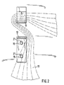
- the device designed according to the invention for draping curtains or the like is characterized by at least one, in particular two, U-shaped holders 10, which are arranged at a horizontal spacing from one another, over the upper legs 11 of which, in the assembled state, a curtain fabric 13 draped into a beam-like bundle is placed is then to be passed from the outside inwards between the upper and lower legs of the holders mentioned in such a way that the curtain material is held onto the holders 10 while maintaining the predetermined draping.
- the lower leg of the holder 10 designed according to the invention is identified in FIGS. 1 and 2 by the reference number 12.
- the U-shaped holder 10 is bent from a flat strip profile, namely painted flat iron, the upper leg 11, in the assembled state, being somewhat shorter than the lower leg 12, with which the holder 10 can be fastened to an upright wall 14 (fastening screws 15 ).
- the upper leg 11 in the assembled state is at its free, ie. H. the end facing the wall 14, first bent upward and then forward downward to form a downwardly open C-shaped or U-shaped end 16 which literally clamps the curtain fabric placed over the upper leg 11 (see FIG. 1).
- the end or inside end 16 of the upper leg 11 thus serves both as a lateral and an upper stop with a clamping effect compared to the curtain fabric placed over the upper leg 11, provided, of course, that it becomes a balkenar term bundle of draped curtain fabric has a greater height than the distance between the lower end of the end 16 and the top of the upper leg 11. To ensure this, this distance is preferably about 5 to 10 mm, in particular about 6 to 7 mm.
- the free end of the lower leg 12 of the U-shaped holder 10 is bent downward to form a tab-like connecting part 20, by means of which the holder 10 can be fastened to the wall 14, by means of the fastening screws 15 arranged one above the other at a distance
- Purpose are provided in the connecting part 20 through holes 21 (see Fig. 2).
- the holes 21 are formed according to FIG. 2 as elongated holes, so that the holder 10 can be moved slightly in height during assembly for height compensation with a holder of the same type arranged at a horizontal distance.
- a further intermediate leg which is not shown in the present exemplary embodiment, can be provided between the upper leg 11 and the lower leg 12. This extends approximately in parallel to the upper and lower legs, so that the curtain fabric 13 draped into a beam-like bundle can be passed between the upper leg 11 and the intermediate leg on the one hand and the intermediate leg and lower leg 12 a on the other.
- the draped curtain fabric 13 is literally “threaded” through this gap into the area between the upper and lower legs of the holder 10. This "threading” is additionally promoted by the described design of the wall-side end closure 16 of the upper leg 11. There is no danger of the curtain fabric 13 "being threaded” getting caught.
- the upper leg 11 is shorter by a length than that under leg 12, which preferably corresponds approximately to the clear distance between the upper and lower leg.
- the upper leg is slightly inclined towards the lower leg 12 in the direction of its free end, the angle of inclination relative to the lower leg 12 being approximately 5 to 10 °. This results in an increased clamping effect between draped curtain fabric 13 on the one hand and holder 10 on the other hand.
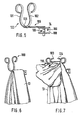
- one or more intermediate holders in the manner of a hook 22 are provided (see FIGS. 3 and 4), which can be fastened to this at a distance from an upright wall or the like.
- the intermediate hook 22 is also bent from a flat strip profile, preferably painted flat iron.
- the free end of the hook is covered by a rosette 23 on the front corresponding to the rosette 18 of the hook 10.
- the wall-side leg 24 of the hook 22 is angled twice through 90 ° to form a wall-parallel connecting part 25, in which at least two holes 26 arranged one above the other are provided for the passage of fastening screws or the like.
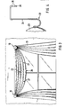
- FIG 3 shows a possible position of the intermediate hook 22 relative to the two edge-side holders 10 with the formation of two draping sheets 27 in dashed lines. If the intermediate hook 22 is omitted, only a single draping sheet 28 can form between the two edge holders 10.
- the intermediate hook 22 can also be designed as a loose U-bracket, which is open at the top in the assembled state, the front leg in turn being covered by a screen in the form of a rosette 23.
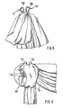
- FIGS. 9-10 show a further embodiment of a draping holder 100 and its use with the formation of fabric rosettes 107 in the region of the holder under cover thereof (see FIGS. 9 and 10).
- the holder 100 literally represents a kind of decorative holder.
- the holder 100 consists of an approximately C-shaped flat ribbon made of metal or the like. It is attached to the wall 14 via an L-shaped support bracket 105 at a distance from it (mounting plate 108 and mounting screws 109 in FIG. 5) such that the plane defined by its two prongs 101, 102 is approximately parallel to the wall 14 or whose surface extends.
- the curtain fabric 13 is first folded over the L-shaped support bracket 105 according to FIG. 6 in a meandering manner. Then, according to FIG. 7, an upper layer of curtain fabric is pulled forward between the two prongs 101 and 102 (see arrow 110 in FIG.
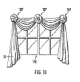
- FIG. 10 shows a curtain 13 that has been draped over a window 116, wherein the draping is carried out using three drapery holders 100 arranged horizontally above the window 116 in accordance with FIG. 5.
Landscapes
- Curtains And Furnishings For Windows Or Doors (AREA)
- Harvester Elements (AREA)
- Forklifts And Lifting Vehicles (AREA)
- Eye Examination Apparatus (AREA)
- Magnetic Resonance Imaging Apparatus (AREA)
- Spinning Or Twisting Of Yarns (AREA)
- Folding Of Thin Sheet-Like Materials, Special Discharging Devices, And Others (AREA)
Abstract
Vorrichtung zum Drapieren von Vorhängen (13) oder dgl. mit mindestens einem, insbesondere zwei im horizontalen Abstand voneinander angeordneten, jeweils etwa U-förmig gebogenen Halter(n) (10), über dessen bzw. deren im montierten Zustand obere(n) Schenkel (11) und zwischen dessen bzw. deren oberen (11) und unteren (12) Schenkel ein zu einem balken- oder brettartigen Bündel gefalteter Vorhangstoff (13) oder dgl. Material leg- bzw. hindurchführbar ist derart, daß er unter Aufrechterhaltung einer vorgegebenen Drapierung festgehalten ist. Eine andere Ausführungsform ist durch einen etwa U- oder C-förmigen Halter gekennzeichnet, der im Abstand von einer Wand (14) oder dgl. befestigt ist,, derart, daß die durch die beiden Zinken bzw. Schenkel des Halters definierte Ebene sich etwa parallel zur Wand erstreckt.Device for draping curtains (13) or the like. With at least one, in particular two, horizontally spaced, approximately U-shaped holder (s) (10), above or in the assembled state of the upper leg (s) (11) and between its or its upper (11) and lower (12) legs a curtain fabric (13) or the like material folded into a beam-like or board-like bundle can be placed or passed through such that it while maintaining a predetermined Drapery is captured. Another embodiment is characterized by an approximately U-shaped or C-shaped holder which is fastened at a distance from a wall (14) or the like, such that the plane defined by the two prongs or legs of the holder is approximately parallel extends to the wall.
Description
Die Erfindung betrifft eine Vorrichtung zum Drapieren von Vorhängen oder dgl.The invention relates to a device for draping curtains or the like.
Beim Drapieren eines Fenster- oder Türvorhangs wird der Vorhangstoff zu einem balkenartigen Bündel zusammengefaltet (Zick-Zack-Faltung bzw. Mäander-Faltung) und über zwei im horizontalen Abstand oberhalb des Fensters oder der Tür angeordnete Haltestäbe gelegt. Anschließend wird zur Herstellung eines Drapierbogens zwischen den beiden Haltestäben der untere Teil des Vorhangstoffs unter Ausbildung von kreissegmentförmigen Falten nach unten gezogen, wobei es äußerst schwierig ist und dementsprechend viel Geschicklichkeit verlangt, die oberste bzw. oberen Falten zwischen den beiden Haltestäben straff zu halten.When draping a window or door curtain, the curtain fabric is folded into a beam-like bundle (zigzag fold or meander fold) and placed over two holding bars arranged horizontally above the window or door. The lower part of the curtain fabric is then pulled down to form a segment of a circle between the two holding rods to produce a draping bow, whereby it is extremely difficult and accordingly requires a great deal of skill to keep the uppermost or upper folds between the two holding rods taut.
Der vorliegenden Erfindung liegt die Aufgabe zugrunde, die erwähnten Haltestäbe zu abzuwandeln, daß bei der Ausbildung eines Drapierbogens die obersten Falten stets straff gehalten werden, ohne daß eine besondere Geschicklichkeit dafür verlangt wird.The present invention has for its object to modify the above-mentioned holding rods that the uppermost folds are always kept taut when a draping sheet is formed, without requiring special skill.
Diese Aufgabe wird in überraschend einfacher Weise durch die Maßnahmen nach Anspruch 1 gelöst, wobei hinsichtlich bevorzugter konstruktiver Details auf die Unteransprüche verwiesen wird.This object is achieved in a surprisingly simple manner by the measures according to claim 1, reference being made to the subclaims for preferred structural details.
Unter Verwendung der erfindungsgemäß ausgebildeten Halter ist es auch für eine ungeübte Person äußerst einfach, einen Drapierbogen zwischen zwei im horizontalen Abstand voneinander angeordneten Haltern auszubilden. Es besteht nicht die Gefahr, daß bei der Ausbildung des Drapierbogens die obersten Falten mit nach unten gezogen werden, so daß der Vorhang zwischen den beiden Haltern regelrecht "durchhängt". Zu diesem Zweck sind auch nicht zwei oder mehr Personen erforderlich, so wie dies beim Drapieren eines Vorhangs oder dgl. nach der herkömmlichen Methode in der Regel notwendig ist, vor allem wenn es sich um größere Drapierbögen bzw. um größere Abstände zwischen den Vorhang-Haltern handelt.Using the holder designed according to the invention, it is extremely simple even for an inexperienced person to form a draping bow between two holders arranged at a horizontal distance from one another. There is no danger that the uppermost folds will be pulled downward when the draping sheet is being formed, so that the curtain between the two holders literally "sags". For this purpose, two or more people are not required, as is usually necessary when draping a curtain or the like according to the conventional method, especially when it comes to larger draping sheets or larger distances between the curtain holders acts.
Vorzugsweise besteht der erfindungsgemäß ausgebildete Halter aus einem U-förmig gebogenen Flachbandprofil, insbesondere Flacheisen, wobei der im montierten Zustand obere Schenkel kürzer bemessen ist als der untere Schenkel, mit dem der Halter an einer aufrechten Wand oder dgl. befestigbar ist. Bei dieser Ausführungsform handelt es sich um eine besonders einfache Konstruktion, die dementsprechend kostengünstig herstellbar ist.The holder designed according to the invention preferably consists of a U-shaped flat strip profile, in particular flat iron, the upper leg, in the assembled state, being shorter than the lower leg, with which the holder can be fastened to an upright wall or the like. In this embodiment is a particularly simple construction, which is accordingly inexpensive to manufacture.
Besonders hervorzuheben wäre noch die konstruktive Ausführungsform nach Anspruch 8, durch die zusätzlich ein Straffhalten der oberen Falten des Vorhangstoffes zwischen zwei im horizontalen Abstand voneinander angeordneten Haltern der erfindungsgemäßen Art sichergestellt ist.Of particular note would be the structural embodiment according to claim 8, which additionally ensures that the upper folds of the curtain fabric are held tight between two holders of the type according to the invention arranged at a horizontal distance from one another.
Für die Ausbildung von zwei oder mehr Drapierbögen zwischen zwei äußeren Haltern der erfindungsgemäßen Art sind zwei oder mehr Zwischenhalter nach Art eines Hakens vorgesehen, der bzw. die jeweils im Abstand von einer aufrechten Wand oder dgl. an dieser befestigbar sind. Schließlich sei noch die Ausführungsform eines Drapier-Halters nach den Ansprüchen 9 ff., welcher die Ausbildung von Stoff-Rosetten an den Stütz- bzw. Haltepunkten des Vorhanges bzw. Vorhangstoffs erlaubt. Diese Halter stellen regelrechte Zierhalter dar.For the formation of two or more draping sheets between two outer holders of the type according to the invention, two or more intermediate holders are provided in the manner of a hook, which can be attached to the wall at a distance from an upright wall or the like. Finally, there is the embodiment of a drapery holder according to claims 9 ff., Which allows the formation of fabric rosettes at the support or holding points of the curtain or curtain fabric. These holders are real decorative holders.
Nachstehend wird eine bevorzugte Ausführungsform der erfindungsgemäßen Vorrichtung anhand der beigefügten Zeichnung näher erläutert. Es zeigen:
- Fig. 1 einen erfindungsgemäßen ausgebildeten Drapier-Halter in Seitenansicht;
- Fig. 2 den Drapierhaken nach Fig. 1 im Schnitt Längslinie II-II in Fig. 1;
- Fig. 3 die Anordnung der erfindungsgemäßen Drapier-Halter oberhalb eines Fensters unter Darstellung eines zwischen diesen beiden Haltern ausgebildeten Drapierbogens sowie unter Darstellung (gestrichelt) eines Zwischenhalters zur Ausbildung von zwei Drapierbögen zwischen den beiden äußeren Drapierhaken;
- Fig. 4 einen Zwischenhalter in Seitenansicht und verkleinerten Maßstab;
- Fig. 5 eine weitere Ausführungsform eines erfindungsgemäßen Drapier-Halters in perspektivischer Ansicht;
- Fig. 6-9 die Darstellung des Drapierens eines Vorhanges unter Verwendung eines Halters nach Fig. 5 jeweils in perspektivischer Ansicht; und
- Fig. 10 einen fertig drapierten Fenstervorhang unter Verwendung von drei im horizontalen Abstand über dem Fenster angeordneten Drapier-Haltern nach Fig. 5.
- 1 shows a draping holder designed according to the invention in a side view;
- FIG. 2 shows the draping hook according to FIG. 1 in a section along line II-II in FIG. 1;
- 3 shows the arrangement of the draping holder according to the invention above a window, showing a draping sheet formed between these two holders and showing (dashed) an intermediate holder for forming two draping sheets between the two outer draping hooks;
- 4 shows an intermediate holder in a side view and on a reduced scale;
- 5 shows a further embodiment of a draping holder according to the invention in a perspective view;
- Fig. 6-9 the representation of the draping of a curtain using a holder according to Fig 5 each in a perspective view. and
- 10 shows a completely draped window curtain using three drapery holders according to FIG. 5 arranged horizontally above the window.
Die erfindungsgemäß ausgebildete Vorrichtung zum Drapieren von Vorhängen oder dgl. ist gekennzeichnet durch mindestens einen, insbesondere zwei im horizontalen Abstand voneinander angeordnete, U-förmig gebogene Halter 10, über deren im montierten Zustand jeweils obere Schenkel 11 ein zu einem balkenartigen Bündel drapierter Vorhangstoff 13 gelegt wird, um dann von außen nach innen zwischen oberem und unterem Schenkel der genannten Halter hindurchgeführt zu werden derart, daß der Vorhangstoff unter Aufrechterhaltung der vorgegebenen Drapierung an den Haltern 10 festgehalten ist. Der untere Schenkel des erfindungsgemäß ausgebildeten Halters 10 ist in den Figuren 1 und 2 mit der Bezugsziffer 12 gekennzeichnet.The device designed according to the invention for draping curtains or the like is characterized by at least one, in particular two, U-shaped
Der U-förmige Halter 10 ist aus einem Flachbandprofil, nämlich lackiertem Flacheisen, gebogen, wobei der im montierten Zustand obere Schenkel 11 etwas kürzer bemessen ist als der untere Schenkel 12, mit dem der Halter 10 an einer aufrechten Wand 14 befestigbar ist (Befestigungsschrauben 15).The U-shaped
Der im montierten Zustand obere Schenkel 11 ist an seinem freien, d. h. der Wand 14 zugewandten Ende, zunächst nach oben und dann nach vorne unten gebogen unter Ausbildung eines nach unten offenen C- oder U-förmigen Abschlusses 16, der den über den oberen Schenkel 11 gelegten Vorhangstoff regelrecht festklemmt (siehe Fig. 1).The
Der end- bzw. innenseitige Abschluß 16 des oberen Schenkels 11 dient somit sowohl als seitlicher als auch oberer Anschlag mit Klemmwirkung gegenüber dem über den oberen Schenkel 11 gelegten Vorhangstoff, selbstverständlich unter der Voraussetzung, daß der zu einem balkenar tigen Bündel drapierte Vorhangstoff eine größere Höhe aufweist als der Abstand zwischen dem unteren Ende des Abschlusses 16 und der Oberseite des oberen Schenkels 11. Um dies sicherzustellen, beträgt dieser Abstand vorzugsweise etwa 5 bis 10 mm, insbesondere etwa 6 bis 7 mm.The end or inside
Im Bereich der U-förmigen Biegung 17 des Halters 10 ist ebenfalls eine über die Oberseite des oberen Schenkels 11 ragende äußere Begrenzung für den über den oberen Schenkel 11 gelegten Vorhangstoff 13 angeordnet, und zwar in Form einer die U-förmige Biegung (17) des Halters 10 sowohl oben als auch unten überdeckende Rosette 18. Die Rosette 18 wird im Bereich der U-förmigen Biegung 17 des Halters 10 mittels einer in Fig. 1 nur angedeuteten Schraube 19 befestigt. Stattdessen ist auch eine Niet-, Kleb- oder Lötverbindung denkbar.In the area of the U-shaped
Das freie Ende des unteren Schenkels 12 des U-förmig gebogenen Halters 10 ist nach unten gebogen unter Ausbildung eines laschenartigen Anschlußteils 20, über den der Halter 10 an der Wand 14 befestigbar ist, und zwar mittels der im Abstand übereinander angeordneten Befestigungsschrauben 15. Zu diesem Zweck sind im Anschlußteil 20 Durchgangslöcher 21 vorgesehen (siehe Fig. 2). Die Löcher 21 sind entsprechend Fig. 2 als Langlöcher ausgebildet, so daß bei der Montage die Halter 10 geringfügig in der Höhe verschoben werden können zum Höhenausgleich mit einem im horizontalen Abstand angeordneten Halter gleicher Art.The free end of the
Zwischen oberem Schenkel 11 und unterem Schenkel 12 kann noch ein weiterer Zwischenschenkel vorgesehen sein, der bei dem vorliegenden Ausführungsbeispiel nicht dargestellt ist. Dieser erstreckt sich etwa parallel zu dem oberen und unteren Schenkel, so daß der zu einem balkenartigen Bündel drapierte Vorhangstoff 13 zwischen oberem Schenkel 11 und Zwischenschenkel einerseits sowie Zwischenschenkel und unterem Schenkel 12 a ndererseits hindurchführbar ist.A further intermediate leg, which is not shown in the present exemplary embodiment, can be provided between the
Zu der kürzeren Ausbildung des oberen Schenkels 11 gegenüber dem unteren Schenkel 12 des Halters 10 sei noch gesagt, daß dadurch die Einführung des zu einem balken- bzw. brettartigen Bündel drapierten Vorhangstoffs in den Bereich zwischen oberem und unteren Schenkel erheblich erleichtert wird, und zwar durch den Spalt zwischen der aufrechten Wand 14 oder dgl. und dem freien inneren Ende des oberen Schenkels 14 hindurch. Der drapierte Vorhangstoff 13 wird durch diesen Spalt hindurch in den Bereich zwischen oberem und unterem Schenkel des Halters 10 regelrecht "eingefädelt". Dieses "Einfädeln" wird zusätzlich begünstigt durch die beschriebene Ausführung des wandseitigen Endabschlusses 16 des oberen Schenkels 11. Die Gefahr eines Verhakens des "einzufädelnden" Vorhangstoffs 13 besteht nicht. Der obere Schenkel 11 ist um eine Länge kürzer als der unter Schenkel 12, die vorzugsweise etwa dem lichten Abstand zwischen oberem und unterem Schenkel entspricht.Regarding the shorter design of the
Besonders vorteilhaft ist es, wenn der obere Schenkel in Richtung zu seinem freien Ende hin geringfügig zum unteren Schenkel 12 hin geneigt ist, wobei der Neigungswinkel gegenüber dem unteren Schenkel 12 etwa 5 bis 10° beträgt. Dadurch wird eine erhöhte Klemmwirkung zwischen drapiertem Vorhangstoff 13 einerseits und Halter 10 andererseits erhalten.It is particularly advantageous if the upper leg is slightly inclined towards the
Es sei noch darauf hingewiesen, daß in den Figuren 1 und 2 der drapierte Vorhangstoff 13 aus Gründen der verein fachten Darstellung gestrichelte gezeichnet ist.It should also be pointed out that in Figures 1 and 2 the draped
Zur Ausbildung von zwei oder mehr Drapierbögen zwischen zwei äußeren Haltern 10 der beschriebenen Art sind ein oder mehr Zwischenhalter nach Art eines Hakens 22 vorgesehen (siehe Fig. 3 und 4), der im Abstand von einer aufrechten Wand oder dgl. an dieser befestigbar ist.To form two or more draping sheets between two
Konkret ist der Zwischenhaken 22 ebenfalls aus einem Flachbandprofil, vorzugsweise lackiertem Flacheisen gebogen. Das freie Hakenende ist durch eine frontseitige Rosette 23 abgedeckt entsprechend der Rosette 18 des Hakens 10. Zur Befestigung des Hakens 22 im Abstand von einer aufrechten Wand oder dgl. ist der wandseitige Schenkel 24 des Hakens 22 zweimal um 90° abgewinkelt unter Ausbildung eines wandparallelen Anschlußteiles 25, in dem mindestens zwei übereinander angeordnete Löcher 26 für den Durchgang von Befestigungsschrauben oder dgl. vorgesehen sind.Specifically, the
In Fig. 3 ist eine mögliche Position des Zwischenhakens 22 relativ zu den beiden randseitigen Haltern 10 unter Ausbildung von zwei Drapierbögen 27 gestrichelt dargestellt. Wird der Zwischenhaken 22 weggelassen, kann sich zwischen den beiden Randhaltern 10 nur ein einziger Drapierbogen 28 ausbilden.3 shows a possible position of the
Der Zwischenhaken 22 kann auch als loser U-Bügel ausgebildet sein, der im montierten Zustand nach oben offen ist, wobei der vordere Schenkel wiederum durch eine Sichtblende in Form einer Rosette 23 abgedeckt sein kann.The
Unter Verwendung der beschriebenen Halter ist es für jedermann denkbar einfach, Vorhänge zu drapieren, und zwar unter Ausbildung von horizontalen Drapierbögen und drapierten Schals, die von den erfindungsgemäßen ausgebildeten Haltern 10 sich jeweils nach unten erstrecken zur seitlichen Begrenzung eines Fensters oder einer Tür.Using the described holder, it is very easy for anyone to drape curtains, with the formation of horizontal drapes and draped scarves which each extend downward from the
Die Fig. 5-10 zeigen eine weitere Ausführungsform eines Drapier-Halters 100 und dessen Verwendung unter Ausbildung von Stoff-Rosetten 107 im Bereich des Halters unter Abdeckung desselben (siehe Fig. 9 und 10). Insofern stellt der Halter 100 regelrecht eine Art Zierhalter dar.5-10 show a further embodiment of a
Der Halter 100 besteht aus einem etwa C-förmig gebogenen Flachband aus Metall oder dergleichen. Er ist über einen L-förmigen Tragbügel 105 im Abstand von einer Wand 14 an dieser befestigt (Befestigungsplatte 108 und Befestigungsschrauben 109 in Fig. 5) derart, daß die durch seine beiden Zinken 101, 102 definierte Ebene sich etwa parallel zur Wand 14 bzw. dessen Oberfläche erstreckt. Zur Ausbildung der erwähnten Rosetten 107 wird zunächst entsprechend Fig. 6 der Vorhangstoff 13 mäanderförmig übereinandergefaltet über den L-förmigen Tragbügel 105 gelegt. Dann wird entsprechend Fig. 7 eine obere Lage von Vorhangstoff nach vorne zwischen den beiden Zinken 101 und 102 hindurch gezogen (siehe Pfeil 110 in Fig. 7), wobei die beiden Zinken 101, 102 sich dabei federelastisch auseinanderbiegen (siehe Pfeile 103, 104 in Fig. 7). Der Vorhangstoff wird etwa soweit zwischen den beiden Zinken 101, 102 hindurch nach vorne gezogen, wie in Fig. 8 dargestellt. Ist dieser Vorgang beendet, kehren die beiden Zinken 101, 102 entsprechend den Pfeilen 111, 112 wieder in ihre Ausgangslage zurück. Anschließend wird der nach vorne gezogene Teil des Vorhangstoffes 13 zurück über die Zinken 101, 102 und zwischen diesen hindurch entsprechend Fig. 9 gestülpt (siehe Pfeile 113, 114, 115 in Fig. 9), wodurch die gewünschte Rosette 107 entsteht.The
In Fig. 10 ist ein über einem Fenster 116 fertig drapierter Vorhang 13 dargestellt, wobei die Drapierung unter Verwendung von drei im horizontalen Abstand über dem Fenster 116 angeordneten Drapier-Haltern 100 entsprechend Fig. 5 durchgeführt ist.FIG. 10 shows a
Sämtliche in den Unterlagen offenbarten Merkmale werden als erfindungswesentlich beansprucht, soweit sie einzeln oder in Kombination gegenüber dem Stand der Technik neu sind. All features disclosed in the documents are claimed as essential to the invention, insofar as they are new compared to the prior art, individually or in combination.
Claims (11)
gekennzeichnet durch
mindestens einen, insbesondere zwei im horizontalen Abstand voneinander angeordneten, jeweils etwa U-förmig gebogenen Halter(n) (10) , über dessen bzw. deren im montierten Zustand obere(n) Schenkel (11) und zwischen dessen bzw. deren oberen (11) und unteren (12) Schenkel ein zu einem balken- bzw. brettartigen Bündel gefalteter Vorhangstoff (13) leg- bzw. hindurchführbar ist derart, daß er unter Aufrechterhaltung einer vorgegebenen Drapierung festgehalten ist.1. Device for draping curtains or the like,
marked by
at least one, in particular two, horizontally spaced from each other, each approximately U-shaped curved holder (s) (10), over the or their upper (n) legs (11) in the assembled state and between its or their upper (11 ) and lower (12) legs a curtain fabric (13) folded into a beam or board-like bundle can be laid or passed through such that it is held in place while maintaining a predetermined draping.
dadurch gekennzeichnet, , daß der U-förmige Halter (10) aus einem Flachbandprofil, insbesondere Flacheisen oder dgl., gebogen ist, wobei der im montierten Zustand obere Schenkel (11) kürzer bemessen ist als der untere Schenkel (12), mit dem der Halter (10) an einer aufrechten Wand (14) oder dgl. befestigbar ist.2. Device according to claim 1,
characterized in that the U-shaped holder (10) is bent from a flat strip profile, in particular flat iron or the like. The upper leg (11) in the assembled state is shorter than the lower leg (12) with which the Holder (10) can be attached to an upright wall (14) or the like.
dadurch gekennzeichnet,, daß der im montierten Zustand obere Schenkel (11) an seinem wandseitigen freien Ende nach oben gebogen ist unter Ausbildung einer wandseitigen Begrenzung für den über den oberen Schenkel (11) gelegten Vorhangstoff (13), und daß ferner im Bereich der U-förmigen Biegung (17) des Halters (10) ebenfalls eine über die Oberseite des oberen Schenkels (11) ragende äußere Begrenzung für den über den oberen Schenkel (11) gelegten Vorhangstoff (13) angeordnet ist, vorzugsweise in Form einer den U-förmigen Biegeabschnitt (17) des Halters (10) abdeckende Scheibe, Rosette (18) oder dgl. Sichtblende.3. Device according to claim 1 or 2,
characterized in that the upper leg (11) in the assembled state is bent upward at its wall-side free end to form a wall-side boundary for the curtain fabric (13) placed over the upper leg (11), and that in the area of the U -shaped bend (17) of the holder (10) is also an outer limit projecting over the top of the upper leg (11) for the curtain fabric (13) placed over the upper leg (11), preferably in the form of a U-shaped Bending section (17) of the holder (10) covering disc, rosette (18) or the like.
dadurch gekennzeichnet,
, daß das freie Ende des unteren Schenkels (12) des U-förmig gebogenen Halters (10) nach unten bzw. vom oberen Schenkel (12) etwa im rechten Winkel nach unten gebogen ist unter Ausbildung eines Anschlußteils (20), über den der Halter (10) an einer aufrechten Wand (14) oder dgl. befestigbar ist.4. Device according to one of claims 1 to 3,
characterized,
that the free end of the lower leg (12) of the U-shaped holder (10) is bent downwards or from the upper leg (12) at approximately a right angle to form a connecting part (20) via which the holder (10) can be attached to an upright wall (14) or the like.
gekennzeichnet durch
mindestens einen, insbesondere zwei im horizontalen Abstand voneinander angeordneten, jeweils etwa U- oder C-förmig gebogenen Halter(n) (100), der bzw. die so im Abstand von einer Wand (14) oder dergleichen an dieser angeordnet ist bzw. sind, daß sich die durch die beiden Schenkel bzw. Zinken (101, 102) des Halters (100) definierte Ebene etwa parallel zur Wandfläche erstreckt.9. The device, in particular according to one or more of claims 1-8,
marked by
at least one, in particular two, horizontally spaced, approximately U- or C-shaped holder (s) (100), which is or are so spaced from a wall (14) or the like on it that the plane defined by the two legs or prongs (101, 102) of the holder (100) extends approximately parallel to the wall surface.
dadurch gekennzeichnet,,
daß die beiden Zinken (101, 102) federelastisch auseinander biegbar sind (Pfeile 103, 104).10. The device according to claim 9,
characterized ,
that the two tines (101, 102) are resiliently bendable (arrows 103, 104).
dadurch gekennzeichnet,,
daß der Halter (100) über ein L-förmiges Tragelement (105) an der Wand (14) oder dergleichen befestigbar ist, wobei das Tragelement (105) im Bereich des die beiden Zinken (101, 102) des Halters (100) miteinander verbindenden Steges (106) am Halter (100) angeschlossen und sich etwa senkrecht zu der durch die beiden Zinken (101, 102) des Halters (100) definierten Ebene erstreckt.11. The device according to claim 9 or 10,
characterized ,
that the holder (100) can be fastened to the wall (14) or the like via an L-shaped support element (105), the support element (105) connecting the two prongs (101, 102) of the holder (100) to one another Web (106) connected to the holder (100) and extends approximately perpendicular to the plane defined by the two prongs (101, 102) of the holder (100).
Priority Applications (1)
| Application Number | Priority Date | Filing Date | Title |
|---|---|---|---|
| AT87114878T ATE55878T1 (en) | 1986-10-29 | 1987-10-12 | DEVICE FOR DRAPING CURTAINS. |
Applications Claiming Priority (2)
| Application Number | Priority Date | Filing Date | Title |
|---|---|---|---|
| DE19863636845 DE3636845A1 (en) | 1986-10-29 | 1986-10-29 | DEVICE FOR DRAPING CURTAINS OR THE LIKE |
| DE3636845 | 1986-10-29 |
Publications (3)
| Publication Number | Publication Date |
|---|---|
| EP0265759A1 true EP0265759A1 (en) | 1988-05-04 |
| EP0265759B1 EP0265759B1 (en) | 1990-08-29 |
| EP0265759B2 EP0265759B2 (en) | 1997-05-14 |
Family
ID=6312755
Family Applications (1)
| Application Number | Title | Priority Date | Filing Date |
|---|---|---|---|
| EP87114878A Expired - Lifetime EP0265759B2 (en) | 1986-10-29 | 1987-10-12 | Device for draping curtains |
Country Status (6)
| Country | Link |
|---|---|
| US (3) | US4958646A (en) |
| EP (1) | EP0265759B2 (en) |
| AT (1) | ATE55878T1 (en) |
| DE (2) | DE3636845A1 (en) |
| ES (1) | ES2016958B3 (en) |
| GR (1) | GR3001117T3 (en) |
Cited By (2)
| Publication number | Priority date | Publication date | Assignee | Title |
|---|---|---|---|---|
| EP0413058A1 (en) * | 1989-08-16 | 1991-02-20 | AB A. Svensson & Co. | Holder for draping curtains, arrangement of holders and procedure for curtain draping |
| WO1992011792A1 (en) * | 1991-01-07 | 1992-07-23 | Ab A. Svensson & Co. Textil & Snörmakerifabrik | Device and method for hanging curtains |
Families Citing this family (15)
| Publication number | Priority date | Publication date | Assignee | Title |
|---|---|---|---|---|
| DE3636845A1 (en) * | 1986-10-29 | 1988-05-11 | Svensson A & Co Ab | DEVICE FOR DRAPING CURTAINS OR THE LIKE |
| DE8911270U1 (en) * | 1989-08-16 | 1989-11-23 | Aktiebolaget A. Svensson & Co., Malmoe, Se | |
| US5144997A (en) * | 1991-08-09 | 1992-09-08 | Graber Industries, Inc. | Drapery fixture |
| US5141045A (en) * | 1991-04-05 | 1992-08-25 | Williams Johnie E | Drapery bracket assembly and method of forming window treatment |
| US5146972A (en) * | 1992-01-24 | 1992-09-15 | Cooper Industries, Inc. | Method for draping curtains |
| US5238044A (en) * | 1992-10-20 | 1993-08-24 | Gilley Paul D | Window treatment support device |
| US5282505A (en) * | 1992-10-20 | 1994-02-01 | Gilley Paul D | Window treatment support device |
| USD357624S (en) * | 1992-11-13 | 1995-04-25 | Morris Ferdman | Curtain hanger |
| US5305814A (en) * | 1992-12-09 | 1994-04-26 | Cooper Industries, Inc. | Method for forming a bishop tail and bishop sleeve |
| US5307860A (en) * | 1993-04-30 | 1994-05-03 | Wilkinson Gladys J | Drapery support system |
| US5544692A (en) * | 1993-08-03 | 1996-08-13 | Kenney Manufacturing Company | Curtain draping hardware and method for draping curtains |
| CA2472632C (en) * | 2004-06-10 | 2012-08-14 | Zenon Koziak | Curtain holder |
| US8365927B2 (en) * | 2004-06-10 | 2013-02-05 | Zenon Koziak | Curtain holder |
| US20080302936A1 (en) * | 2007-06-06 | 2008-12-11 | Sue Forbes | Ribbon rod assembly |
| US20090044888A1 (en) * | 2007-08-14 | 2009-02-19 | Ganey Thomas J | Methods and systems for protecting fabric articles |
Citations (4)
| Publication number | Priority date | Publication date | Assignee | Title |
|---|---|---|---|---|
| DE449312C (en) * | 1925-05-07 | 1927-09-14 | Hans Ussmueller | Holder for gathered curtains |
| US2244129A (en) * | 1939-07-07 | 1941-06-03 | Kirsch Co | Drapery hardware |
| US2431934A (en) * | 1945-12-12 | 1947-12-02 | Harry F Higgins | Festoon ring bracket |
| US2588246A (en) * | 1950-02-09 | 1952-03-04 | Kenney Mfg Co | Festoon holder |
Family Cites Families (43)
| Publication number | Priority date | Publication date | Assignee | Title |
|---|---|---|---|---|
| CA464275A (en) * | 1950-04-11 | Royer Marcel | Drapery hanger for venetian blind brackets | |
| US247860A (en) * | 1881-10-04 | Lantern-holder | ||
| US464499A (en) * | 1891-12-08 | Window-curtain holder | ||
| CA236021A (en) * | 1923-11-27 | S. Wait Thaddeus | Curtain fixture | |
| US361007A (en) * | 1887-04-12 | Curtain-holder | ||
| US744691A (en) * | 1903-01-27 | 1903-11-17 | Elsie A Porter | Curtain-pole support. |
| US827000A (en) * | 1905-09-06 | 1906-07-24 | Mary E Dinsmore | Curtain-fixture. |
| GB190520736A (en) * | 1905-10-13 | 1906-06-07 | James Arthur Richards | Improvements in Brackets for Draping Curtains and Hanging Draperies |
| US851678A (en) * | 1906-07-09 | 1907-04-30 | Charles Levy | Drapery-supporting device. |
| US1037074A (en) * | 1910-05-28 | 1912-08-27 | Splitdorf Electrical Co | Make-and-break device. |
| US1134533A (en) * | 1914-11-11 | 1915-04-06 | Waterbury Mfg Co | Shade or globe holder. |
| CA187246A (en) * | 1916-11-13 | 1918-10-29 | Sidney C. Hills | Curtain rod |
| US1530180A (en) * | 1924-01-07 | 1925-03-17 | Arthur F Biser | Brush holder |
| US1637704A (en) * | 1924-03-13 | 1927-08-02 | Allen A Moats | Curtain-draping device |
| US1644105A (en) * | 1926-04-16 | 1927-10-04 | Boye James H Mfg Co | Bracket and rod coupling for curtain fixtures |
| US1730979A (en) * | 1927-06-06 | 1929-10-08 | Bessie Goldberg | Drapery-holding device |
| US1741182A (en) * | 1928-08-03 | 1929-12-31 | Boye James H Mfg Co | Tie back for curtains and drapes |
| US1874813A (en) * | 1929-09-28 | 1932-08-30 | Benjamin P Saunders | Combination holder |
| US1876026A (en) * | 1930-08-25 | 1932-09-06 | Clarence E Schinkal | Detachable tie-back for drapes and curtains |
| US1817962A (en) * | 1930-10-17 | 1931-08-11 | Breuer Fred | Adjustable curtain holder |
| US1836018A (en) * | 1931-01-13 | 1931-12-15 | Dovercraft Company Inc | Curtain holding means |
| US1980918A (en) * | 1934-04-02 | 1934-11-13 | George T Hudspeth | Curtain and drapery holder |
| GB473669A (en) * | 1936-04-23 | 1937-10-18 | Algernon Eric Vellere | Brackets for supporting window furnishings such as curtains, blinds, valances, and the like |
| US2459503A (en) * | 1945-06-11 | 1949-01-18 | Henry Hildebrandt | Bracket |
| US2480360A (en) * | 1947-10-27 | 1949-08-30 | Chester C Doty | Window shade and curtain fixture |
| US2606733A (en) * | 1948-03-25 | 1952-08-12 | Julia B Krajewski | Drapery fitting |
| US2607412A (en) * | 1949-05-11 | 1952-08-19 | Vance John Selby | Drapery hanging assembly |
| US2637384A (en) * | 1951-11-20 | 1953-05-05 | Mccabe Harold | Drapery holder and looper |
| GB785300A (en) * | 1954-05-28 | 1957-10-23 | Neil Archibald Primrose Lord P | Improvements in or relating to spring clip devices |
| US2909354A (en) * | 1957-10-07 | 1959-10-20 | Thompson Ramo Wooldridge Inc | Retaining device |
| FR1215456A (en) * | 1958-02-03 | 1960-04-19 | United Carr Fastener Corp | Elastic clamp for fixing transistors and similar devices on a support |
| FR1214456A (en) * | 1958-12-06 | 1960-04-08 | Boehler & Co Ag Geb | Switching device, in particular for compressed air devices |
| US3104086A (en) * | 1961-07-14 | 1963-09-17 | Graber Mfg Company Inc | Adjustable support bracket for curtain rods and the like |
| US3203469A (en) * | 1963-04-10 | 1965-08-31 | Douglass R Falkenberg | Drapery support and mounting |
| US3317167A (en) * | 1965-11-02 | 1967-05-02 | United Carr Inc | Fastener combination for securing tubular structures |
| US3417807A (en) * | 1966-03-23 | 1968-12-24 | Douglass R. Falkenberg | Adapter for drapery support |
| US3545523A (en) * | 1968-08-26 | 1970-12-08 | Douglas Mfg Co | Drapery holder |
| GB1278118A (en) * | 1969-11-28 | 1972-06-14 | H W Dowling & Sons | Devices for hanging articles from doors |
| US3901303A (en) * | 1974-04-25 | 1975-08-26 | Douglas Manufacturing Co Inc | Drapery holder |
| US4284258A (en) * | 1979-04-25 | 1981-08-18 | Stanley Kleiman | Festoon support device |
| DE8337252U1 (en) * | 1983-12-24 | 1984-04-12 | Vogtländische Gardinenweberei Renz & Sohn GmbH, 7525 Bad Schönborn | DECORATION CARRIER |
| DE3636845A1 (en) * | 1986-10-29 | 1988-05-11 | Svensson A & Co Ab | DEVICE FOR DRAPING CURTAINS OR THE LIKE |
| US4912829A (en) * | 1987-12-16 | 1990-04-03 | Hickey Donna M | Drapery tie |
-
1986
- 1986-10-29 DE DE19863636845 patent/DE3636845A1/en not_active Withdrawn
-
1987
- 1987-10-12 DE DE8787114878T patent/DE3764605D1/en not_active Expired - Fee Related
- 1987-10-12 AT AT87114878T patent/ATE55878T1/en active
- 1987-10-12 ES ES87114878T patent/ES2016958B3/en not_active Expired - Lifetime
- 1987-10-12 EP EP87114878A patent/EP0265759B2/en not_active Expired - Lifetime
-
1989
- 1989-06-22 US US07/370,340 patent/US4958646A/en not_active Expired - Fee Related
- 1989-12-15 US US07/451,097 patent/US5018567A/en not_active Expired - Fee Related
-
1990
- 1990-11-28 GR GR90400980T patent/GR3001117T3/en unknown
-
1991
- 1991-01-14 US US07/640,936 patent/US5078199A/en not_active Expired - Fee Related
Patent Citations (4)
| Publication number | Priority date | Publication date | Assignee | Title |
|---|---|---|---|---|
| DE449312C (en) * | 1925-05-07 | 1927-09-14 | Hans Ussmueller | Holder for gathered curtains |
| US2244129A (en) * | 1939-07-07 | 1941-06-03 | Kirsch Co | Drapery hardware |
| US2431934A (en) * | 1945-12-12 | 1947-12-02 | Harry F Higgins | Festoon ring bracket |
| US2588246A (en) * | 1950-02-09 | 1952-03-04 | Kenney Mfg Co | Festoon holder |
Cited By (4)
| Publication number | Priority date | Publication date | Assignee | Title |
|---|---|---|---|---|
| EP0413058A1 (en) * | 1989-08-16 | 1991-02-20 | AB A. Svensson & Co. | Holder for draping curtains, arrangement of holders and procedure for curtain draping |
| WO1992011792A1 (en) * | 1991-01-07 | 1992-07-23 | Ab A. Svensson & Co. Textil & Snörmakerifabrik | Device and method for hanging curtains |
| US5343925A (en) * | 1991-01-07 | 1994-09-06 | Ab A. Svensson & Co. | Device for draping curtains |
| US6213190B1 (en) | 1991-01-07 | 2001-04-10 | Ab A. Svensson & Co. | Device for and method of draping curtains |
Also Published As
| Publication number | Publication date |
|---|---|
| US4958646A (en) | 1990-09-25 |
| GR3001117T3 (en) | 1992-05-12 |
| US5078199A (en) | 1992-01-07 |
| EP0265759B2 (en) | 1997-05-14 |
| DE3764605D1 (en) | 1990-10-04 |
| DE3636845A1 (en) | 1988-05-11 |
| EP0265759B1 (en) | 1990-08-29 |
| ATE55878T1 (en) | 1990-09-15 |
| ES2016958B3 (en) | 1990-12-16 |
| US5018567A (en) | 1991-05-28 |
Similar Documents
| Publication | Publication Date | Title |
|---|---|---|
| EP0265759B2 (en) | Device for draping curtains | |
| DE4111067A1 (en) | DEVICE AND METHOD FOR DRAPING CURTAINS | |
| DE2106990A1 (en) | Fixing device for facing brick | |
| DE2003366A1 (en) | Curtain hanging device and rail and combined sliding hooks | |
| DE1638974U (en) | CLAMP FOR FASTENING SEAT COVERS. | |
| DE7530601U (en) | BRACKET FOR A WALL CABINET | |
| DE834894C (en) | Bracket for fastening seat covers | |
| DE818111C (en) | Head bar arrangement for board curtains | |
| DE2825173C2 (en) | Cassette-shaped ceiling or wall cladding element | |
| DE805918C (en) | Device for carrying various types of window hangings | |
| DE3332622A1 (en) | Rain protection for window boxes | |
| DE7630018U1 (en) | HANGING DEVICE FOR CURTAINS OR DGL. | |
| DE2252530C3 (en) | Holding device for the head rail of a slatted external venetian blind | |
| CH391985A (en) | Adjustable support element for curtains | |
| DE2156757C3 (en) | Suspension device for wall cladding panels | |
| EP0413058B1 (en) | Holder for draping curtains, arrangement of holders and procedure for curtain draping | |
| DE1509982A1 (en) | Cladding and fastening of external blinds | |
| DE3390047T1 (en) | Push-in curtain hooks | |
| CH695909A5 (en) | Clip. | |
| AT393855B (en) | Roof structure | |
| DE8001798U1 (en) | Substructure for small-format cladding panels | |
| DE7002968U (en) | SHELVING UNIT. | |
| CH657032A5 (en) | CURTAIN, ESPECIALLY STRIP CURTAIN TO COVER TRANSIT AND CONTINUITY. | |
| DE2823036A1 (en) | Panelled girder framed wall or ceiling - has universal elastic spreader clamps with bent arms on strip supports | |
| DE1792384U (en) | FASTENING DEVICE FOR WINDOW BLINDS. |
Legal Events
| Date | Code | Title | Description |
|---|---|---|---|
| PUAI | Public reference made under article 153(3) epc to a published international application that has entered the european phase |
Free format text: ORIGINAL CODE: 0009012 |
|
| AK | Designated contracting states |
Kind code of ref document: A1 Designated state(s): AT BE CH DE ES FR GB GR IT LI NL SE |
|
| 17P | Request for examination filed |
Effective date: 19880429 |
|
| 17Q | First examination report despatched |
Effective date: 19890823 |
|
| ITF | It: translation for a ep patent filed |
Owner name: ST. ASSOC. MARIETTI & PIPPARELLI |
|
| GRAA | (expected) grant |
Free format text: ORIGINAL CODE: 0009210 |
|
| AK | Designated contracting states |
Kind code of ref document: B1 Designated state(s): AT BE CH DE ES FR GB GR IT LI NL SE |
|
| REF | Corresponds to: |
Ref document number: 55878 Country of ref document: AT Date of ref document: 19900915 Kind code of ref document: T |
|
| ET | Fr: translation filed | ||
| REF | Corresponds to: |
Ref document number: 3764605 Country of ref document: DE Date of ref document: 19901004 |
|
| GBT | Gb: translation of ep patent filed (gb section 77(6)(a)/1977) | ||
| PLBI | Opposition filed |
Free format text: ORIGINAL CODE: 0009260 |
|
| PLBI | Opposition filed |
Free format text: ORIGINAL CODE: 0009260 |
|
| 26 | Opposition filed |
Opponent name: S.A.ATELIERS GUILLAUME VANROY WERKHUIZEN N.Y. Effective date: 19910410 |
|
| 26 | Opposition filed |
Opponent name: S.A.ATELIERS GUILLAUME VANROY WERKHUIZEN N.Y. Effective date: 19910410 Opponent name: COOPER INDUSTRIES INC. Effective date: 19910524 |
|
| REG | Reference to a national code |
Ref country code: GR Ref legal event code: FG4A Free format text: 3001117 |
|
| NLR1 | Nl: opposition has been filed with the epo |
Opponent name: S.A. ATELIERS GUILLAUME VANROY WERKHUIZEN N.Y. |
|
| NLR1 | Nl: opposition has been filed with the epo |
Opponent name: COOPER INDUSTRIES INC . |
|
| PGFP | Annual fee paid to national office [announced via postgrant information from national office to epo] |
Ref country code: GR Payment date: 19911023 Year of fee payment: 5 |
|
| ITTA | It: last paid annual fee | ||
| PG25 | Lapsed in a contracting state [announced via postgrant information from national office to epo] |
Ref country code: GR Free format text: THE PATENT HAS BEEN ANNULLED BY A DECISION OF A NATIONAL AUTHORITY Effective date: 19930430 |
|
| PGFP | Annual fee paid to national office [announced via postgrant information from national office to epo] |
Ref country code: AT Payment date: 19941012 Year of fee payment: 8 |
|
| PGFP | Annual fee paid to national office [announced via postgrant information from national office to epo] |
Ref country code: CH Payment date: 19941014 Year of fee payment: 8 |
|
| PGFP | Annual fee paid to national office [announced via postgrant information from national office to epo] |
Ref country code: ES Payment date: 19941031 Year of fee payment: 8 |
|
| PGFP | Annual fee paid to national office [announced via postgrant information from national office to epo] |
Ref country code: BE Payment date: 19941208 Year of fee payment: 8 |
|
| REG | Reference to a national code |
Ref country code: GR Ref legal event code: MM2A Free format text: 3001117 |
|
| EAL | Se: european patent in force in sweden |
Ref document number: 87114878.9 |
|
| PG25 | Lapsed in a contracting state [announced via postgrant information from national office to epo] |
Ref country code: AT Effective date: 19951012 |
|
| PG25 | Lapsed in a contracting state [announced via postgrant information from national office to epo] |
Ref country code: BE Effective date: 19951031 Ref country code: CH Effective date: 19951031 Ref country code: LI Effective date: 19951031 |
|
| BERE | Be: lapsed |
Owner name: A.B. A. SVENSSON & CO. Effective date: 19951031 Owner name: SUNWECO A.B. Effective date: 19951031 |
|
| REG | Reference to a national code |
Ref country code: CH Ref legal event code: PL |
|
| PGFP | Annual fee paid to national office [announced via postgrant information from national office to epo] |
Ref country code: FR Payment date: 19961016 Year of fee payment: 10 |
|
| PGFP | Annual fee paid to national office [announced via postgrant information from national office to epo] |
Ref country code: GB Payment date: 19961024 Year of fee payment: 10 |
|
| PGFP | Annual fee paid to national office [announced via postgrant information from national office to epo] |
Ref country code: NL Payment date: 19961029 Year of fee payment: 10 |
|
| PLAW | Interlocutory decision in opposition |
Free format text: ORIGINAL CODE: EPIDOS IDOP |
|
| PGFP | Annual fee paid to national office [announced via postgrant information from national office to epo] |
Ref country code: DE Payment date: 19961126 Year of fee payment: 10 |
|
| APAC | Appeal dossier modified |
Free format text: ORIGINAL CODE: EPIDOS NOAPO |
|
| APAC | Appeal dossier modified |
Free format text: ORIGINAL CODE: EPIDOS NOAPO |
|
| PUAH | Patent maintained in amended form |
Free format text: ORIGINAL CODE: 0009272 |
|
| STAA | Information on the status of an ep patent application or granted ep patent |
Free format text: STATUS: PATENT MAINTAINED AS AMENDED |
|
| 27A | Patent maintained in amended form |
Effective date: 19970514 |
|
| AK | Designated contracting states |
Kind code of ref document: B2 Designated state(s): AT BE CH DE ES FR GB GR IT LI NL SE |
|
| GBTA | Gb: translation of amended ep patent filed (gb section 77(6)(b)/1977) | ||
| REG | Reference to a national code |
Ref country code: CH Ref legal event code: AEN Free format text: AUFRECHTERHALTUNG DES PATENTES IN GEAENDERTER FORM |
|
| NLR2 | Nl: decision of opposition | ||
| ET3 | Fr: translation filed ** decision concerning opposition | ||
| PG25 | Lapsed in a contracting state [announced via postgrant information from national office to epo] |
Ref country code: ES Free format text: LAPSE BECAUSE OF FAILURE TO SUBMIT A TRANSLATION OF THE DESCRIPTION OR TO PAY THE FEE WITHIN THE PRESCRIBED TIME-LIMIT Effective date: 19970825 |
|
| NLR3 | Nl: receipt of modified translations in the netherlands language after an opposition procedure | ||
| PG25 | Lapsed in a contracting state [announced via postgrant information from national office to epo] |
Ref country code: GB Free format text: LAPSE BECAUSE OF NON-PAYMENT OF DUE FEES Effective date: 19971012 |
|
| PG25 | Lapsed in a contracting state [announced via postgrant information from national office to epo] |
Ref country code: FR Free format text: THE PATENT HAS BEEN ANNULLED BY A DECISION OF A NATIONAL AUTHORITY Effective date: 19971031 |
|
| PG25 | Lapsed in a contracting state [announced via postgrant information from national office to epo] |
Ref country code: NL Free format text: LAPSE BECAUSE OF NON-PAYMENT OF DUE FEES Effective date: 19980501 |
|
| GBPC | Gb: european patent ceased through non-payment of renewal fee |
Effective date: 19971012 |
|
| NLV4 | Nl: lapsed or anulled due to non-payment of the annual fee |
Effective date: 19980501 |
|
| PG25 | Lapsed in a contracting state [announced via postgrant information from national office to epo] |
Ref country code: DE Free format text: LAPSE BECAUSE OF NON-PAYMENT OF DUE FEES Effective date: 19980701 |
|
| REG | Reference to a national code |
Ref country code: FR Ref legal event code: ST |
|
| PGFP | Annual fee paid to national office [announced via postgrant information from national office to epo] |
Ref country code: SE Payment date: 20000502 Year of fee payment: 13 |
|
| PG25 | Lapsed in a contracting state [announced via postgrant information from national office to epo] |
Ref country code: SE Free format text: THE PATENT HAS BEEN ANNULLED BY A DECISION OF A NATIONAL AUTHORITY Effective date: 20001030 |
|
| EUG | Se: european patent has lapsed |
Ref document number: 87114878.9 |
|
| APAH | Appeal reference modified |
Free format text: ORIGINAL CODE: EPIDOSCREFNO |
|
| PG25 | Lapsed in a contracting state [announced via postgrant information from national office to epo] |
Ref country code: IT Free format text: LAPSE BECAUSE OF NON-PAYMENT OF DUE FEES Effective date: 20051012 |
|
| PG25 | Lapsed in a contracting state [announced via postgrant information from national office to epo] |
Ref country code: ES Free format text: LAPSE BECAUSE OF FAILURE TO SUBMIT A TRANSLATION OF THE DESCRIPTION OR TO PAY THE FEE WITHIN THE PRESCRIBED TIME-LIMIT Effective date: 19951031 |