EP0265721A2 - Moyen pour fabriquer des montages bras/tête magnétique de lecture-écriture en film mince - Google Patents
Moyen pour fabriquer des montages bras/tête magnétique de lecture-écriture en film mince Download PDFInfo
- Publication number
- EP0265721A2 EP0265721A2 EP87114574A EP87114574A EP0265721A2 EP 0265721 A2 EP0265721 A2 EP 0265721A2 EP 87114574 A EP87114574 A EP 87114574A EP 87114574 A EP87114574 A EP 87114574A EP 0265721 A2 EP0265721 A2 EP 0265721A2
- Authority
- EP
- European Patent Office
- Prior art keywords
- slider
- head
- suspension arm
- cable
- thin film
- Prior art date
- Legal status (The legal status is an assumption and is not a legal conclusion. Google has not performed a legal analysis and makes no representation as to the accuracy of the status listed.)
- Granted
Links
Images


Classifications
-
- G—PHYSICS
- G11—INFORMATION STORAGE
- G11B—INFORMATION STORAGE BASED ON RELATIVE MOVEMENT BETWEEN RECORD CARRIER AND TRANSDUCER
- G11B5/00—Recording by magnetisation or demagnetisation of a record carrier; Reproducing by magnetic means; Record carriers therefor
- G11B5/48—Disposition or mounting of heads or head supports relative to record carriers ; arrangements of heads, e.g. for scanning the record carrier to increase the relative speed
- G11B5/4806—Disposition or mounting of heads or head supports relative to record carriers ; arrangements of heads, e.g. for scanning the record carrier to increase the relative speed specially adapted for disk drive assemblies, e.g. assembly prior to operation, hard or flexible disk drives
- G11B5/4853—Constructional details of the electrical connection between head and arm
-
- G—PHYSICS
- G11—INFORMATION STORAGE
- G11B—INFORMATION STORAGE BASED ON RELATIVE MOVEMENT BETWEEN RECORD CARRIER AND TRANSDUCER
- G11B5/00—Recording by magnetisation or demagnetisation of a record carrier; Reproducing by magnetic means; Record carriers therefor
- G11B5/127—Structure or manufacture of heads, e.g. inductive
- G11B5/31—Structure or manufacture of heads, e.g. inductive using thin films
- G11B5/3103—Structure or manufacture of integrated heads or heads mechanically assembled and electrically connected to a support or housing
-
- G—PHYSICS
- G11—INFORMATION STORAGE
- G11B—INFORMATION STORAGE BASED ON RELATIVE MOVEMENT BETWEEN RECORD CARRIER AND TRANSDUCER
- G11B5/00—Recording by magnetisation or demagnetisation of a record carrier; Reproducing by magnetic means; Record carriers therefor
- G11B5/127—Structure or manufacture of heads, e.g. inductive
- G11B5/31—Structure or manufacture of heads, e.g. inductive using thin films
- G11B5/3163—Fabrication methods or processes specially adapted for a particular head structure, e.g. using base layers for electroplating, using functional layers for masking, using energy or particle beams for shaping the structure or modifying the properties of the basic layers
Definitions
- This invention relates to an improved method of assembling a thin film magnetic head to a suspension arm assembly. More particularly, this invention relates to a method of assembling a thin film magnetic head/slider to a suspension arm by contact soldering of said magnetic head/slider to said suspension arm for the purpose of simultaneously affixing the said head/slider to the said suspension arm while also establishing electrical contact to the head/slider.
- FIG. 1 shows a typical head/suspension arm assembly as known in the prior art. From the FIGURE it can be readily seen that the head assembly 9 is mechanically attached to a flexure support 7 of the suspension 5. Electrical connection 15 is made to the head assembly 9 by wire bonding of the twisted pair wiring 13. Mechanical and electrical connection are thus two separate assembly operations requiring separate, and numerous process steps.
- a basic limiting factor of the presently known head/suspension assembly has been the skill in the art for manufacturing the thin film magnetic read/write head and slider assemblies.
- thin film conductors are deposited as a spiral on the face of a ceramic substrate and have replaced the coil of wound wires as part of an inductive circuit for the magnetic read/write transducer.
- the spiral is arranged such that it is positioned in one of the rails of the slider with the electromagnetic head positioned on the trailing edge of the slider structure.
- wire bonding has replaced soldering for connecting the electromagnetic head to the controller circuitry, the wires must still be assembled and laced across the suspension arm. The assembly operations are still time consuming and largely manual.
- a thin film magnetic read/write head/slider is joined to a suspension arm assembly by a solder assembly of said read/write head/slider to a thin cable interface on the suspension arm which provides both mechanical support and electrical interconnection of said read/write head/slider to said suspension arm and to external circuitry.
- the thin film head/slider is of a special design such that the heretofore known wiring bonding interfaces located on the trailing edge of said slider are now positioned on the opposite to disk side of the slider (top side of the slider).
- the head/slider to suspension arm connection now provides a contact interface for other semiconductor devices to be positioned directly on said head/slider.
- Associated semiconductor devices can be either joined to the thin cable interface prior to the solder joining of said suspension arm to the head/slider, or can be joined at the same time.
- the devices can also be joined to the slider directly or to a multilayer ceramic or silicon or any other material carrier or interposer which withstands soldering temperature interposer placed between the slider and device.
- a suspension arm assembly 1 is shown.
- the assembly is divided into three parts: a mounting plate 3, a load beam 5 with flexure support 7 and a head/slider assembly 9.
- the mounting plate 3 serves to mount the suspension assembly 1 onto arm platforms (not shown). It will be appreciated by those skilled in the art that the platforms can be either fixed or movable and control the locating of the head/slider combination over selected disk tracks.
- load beam 5 Assembled to the mounting plate 3 is load beam 5 with flexure support 7.
- the load beam 5 serves to counter-balance and position the head/slider a predetermined distance above the disk.
- the load beam 5 includes crimp tab 5A and front support fork 5B which act as a guide for running the twisted pair wiring 13 from the computer circuitry (not shown) to the head/slider 11.
- flexure support 7 Opposite the mounting plate 3 and located on load beam 5 is flexure support 7.
- the flexure support 7 acts to counterbalance the aerodynamic forces set up by the slider 11 and provides support for said slider 11 which is epoxy bonded thereto. Further, the flexure support 7 also provides support and dresses the twisted pair wiring to the head/slider 11.
- head/slider 11 can be any currently practiced thin film magnetic read/write head/slider.
- the slider itself can include a variety of rail designs to provide the specific aerodynamic equilibrium desired.
- the electromagnet for the head is comprised of a thin, pancake like, spiral film 20 electrical conductor deposited on the slider substrate.
- the magnetic yoke 22 of the head is typically permalloy: an alloy of nickel and iron and is designed to include a predetermined read/write gap (glass) 24 and data track width 26 to be compatible with the disk format.
- the read/write transducer is located at the trailing edge of the slider and has contact pads 28 located on said same trailing edge for electrical interconnection to the computer circuitry.
- assembly of the above suspension arm with the head/slider attached thereto as practiced today is a very labor intensive and costly process requiring successive fixturing, aligning, and baking and bonding operations.
- a cross-section of the embodiment of a head/slider attached to a suspension arm according to the subject invention is shown.
- the flexure arm 31 is in a close and laminate relationship with cable 33.
- the cables 33 are able to be affixed to the suspension arm by any number of means including but not limited to epoxying and/or mechanical retention and that any configuration of thin multiconductor cables can be substituted for the cables 33 as long as the laminate relationship with the flexure is maintained.
- the configuration of the suspension arm and cables can be replaced by an assembly using polyimide, such as the KAPTON brand of polyimide manufactured by DUPONT.
- polyimide such as the KAPTON brand of polyimide manufactured by DUPONT.
- the polyimide is used as the suspension arm and electrical conductors are then vapor deposited by conventional deposition process directly onto said polyimide material.
- an additional layer of polyimide can be bonded over the portion of exposed conductors between the head/slider and mounting plate connections.
- solder connections 37 can be any type of known solid contact soldering including but not limited to copper ball soldering and/or controlled collapse Sn or Sn Pb soldering or metal alloys substituted therefore.
- solder contact pads 39 have been created on the opposite to disk side of the head/slider (top side of the head/slider).
- These contact pads 39 have been specially processed to comprise a profile of first, a layer of chromium/copper for bonding to the aluminum oxide layer of the head/slider, with, next a layer copper deposited onto said first layer for solderability and wetting, and, then, a layer of solder is deposited in a pattern on the layer of copper to complete the pad.
- solder contact pads 39 have been specially processed to comprise a profile of first, a layer of chromium/copper for bonding to the aluminum oxide layer of the head/slider, with, next a layer copper deposited onto said first layer for solderability and wetting, and, then, a layer of solder is deposited in a pattern on the layer of copper to complete the pad.
- the slider as illustrated in Fig. 3 and as described above can be fabricated by using the following process.
- Figs. 4-15 identical numbering has been used to identify like components between the FIGURES.
- Fig. 4 an exploded cross-section side view of the trailing edge of a thin film slider is shown, said slider having been processed through contact stud plating by those skills already known in the art.
- an aluminum oxide (Al2O3) layer 3 Onto said layer of aluminum oxide 3 is deposited successive layers of permalloy 5, copper 7, and permalloy lead 9; permalloy lead being the lead alloy of permalloy.
- permalloy layer 9 are copper studs 11 and aluminum oxide layer 13.
- a relatively thin blanket layer (0.5-2.0 micron) 15 of aluminum oxide or other suitable dielectric material is sputtered or vacuum deposited thereon.
- the substrate (wafer) is then sliced into sliders and polished to yield the slider of Fig. 4.
- a second blanket layer 17 of aluminum oxide, or other dielectric material, is then vacuum deposited onto the polished backside of the slider as shown in Fig. 5.
- a layer of AZ resist 19 is spun onto the aluminum oxide layer 17 (Fig. 6) after suitable drying.
- the resist is subsequently exposed and developed to uncover the aluminum oxide layer 17 immediately over the copper or gold studs 11 as shown in Fig. 7.
- the resist is then reflowed at approximately 100-180°C to create a smooth resist contour (Fig. 8); the reflow step being unnecessary should chemical etching of the aluminum oxide, rather than sputter etching be used in the following step.
- the layer of aluminum oxide 17 is then sputter etched to expose the copper or gold studs 11.
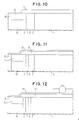
- the resist is then stripped from the slider leaving the aluminum oxide layer 17 in the contour as shown in Fig. 10.
- a thin Cr/Cu, Cr/Cu/Au, Ti/Cu, Ti/Cu/Au, or any other suitable appropriate solder limiting metallurgy layer 21 that would also serve in this application as a seed layer for subsequent plating operations is subsequently vacuum deposited on the Al2O3 layer 17 (Fig. 11).
- a photoresist 23 is then spun, dried, exposed, and developed to form a desired metallization pattern on the slider back plane.
- This metallization pattern 25 serves to provide electrical contact to the cabling and/or to semiconductor chips, or any other structural attachments to the suspension arm and head/slider assembly.
- the metallization pattern comprises a thick Cu (preferred), Ni, or Au layer 25 which is plated through a mask or deposited by other suitable selective means onto the (Al2O3) layer 21 to the pattern of the photoresist 23 (Fig. 13).
- the photoresist 23 can be removed with acetone, by blanket exposure and development or by any other suitable means.
- the seed layer is then sputter-etched in argon (or argon and freon in the case of Ti-containing seed layer), to remove the seed layer 21 from those regions not coated with thick Cu (or Ni or Au) (Fig. 14).
- a solder mask 27 (photoresist, riston, aluminum oxide, glass, or other suitable dielectric material) is then applied, and patterned to contact areas for solder deposition.
- Mask 27 coats and protects all other areas of the back side of the slider (Fig. 15).
- Solder, or braze, is then deposited onto the exposed areas of Fig. 15.
- Fig. 16 is the most basic configuration of the embodiment with the slider 35 directly contact soldered onto the flat cable 33 which is laminated to the flexure 31.
- Fig. 17 shows a different assembly of the suspension arm/slider/head assembly.
- the flexure 31 has now been split to accommodate the slider 35 mid-span. This relationship is necessitated by the particular method of accessing and recording data on the disks.
- the flat cable 33 laminated to the flexure 31 has been separated to also span the slider 35.
- a semiconductor chip 40 is soldered directly to and carried by slider 35.
- This joining of the slider to the semiconductor chip results in effective minimization of noise and eliminates the need for extension circuitry to accomplish the same.
- the slider 35 is then attached at each of its end by contact soldering or brazing 37 said slider to flat cable 33 to bring out the resultant signal from the transducer to the signal processor.
- epoxy 42 can be added to increase the support of the contact soldering 37, if necessary or additional dummy solder pad connections can be made.
- Fig. 18 shows another style of a suspension arm assembly incorporating the split flexure and cable design of Fig. 17.
Landscapes
- Engineering & Computer Science (AREA)
- Manufacturing & Machinery (AREA)
- Adjustment Of The Magnetic Head Position Track Following On Tapes (AREA)
- Supporting Of Heads In Record-Carrier Devices (AREA)
Applications Claiming Priority (2)
| Application Number | Priority Date | Filing Date | Title |
|---|---|---|---|
| US923942 | 1986-10-28 | ||
| US06/923,942 US4789914A (en) | 1986-10-28 | 1986-10-28 | Thin film magnetic read-write head/arm assemblies |
Publications (3)
| Publication Number | Publication Date |
|---|---|
| EP0265721A2 true EP0265721A2 (fr) | 1988-05-04 |
| EP0265721A3 EP0265721A3 (en) | 1989-03-08 |
| EP0265721B1 EP0265721B1 (fr) | 1992-03-04 |
Family
ID=25449499
Family Applications (1)
| Application Number | Title | Priority Date | Filing Date |
|---|---|---|---|
| EP87114574A Expired EP0265721B1 (fr) | 1986-10-28 | 1987-10-06 | Moyen pour fabriquer des montages bras/tête magnétique de lecture-écriture en film mince |
Country Status (4)
| Country | Link |
|---|---|
| US (1) | US4789914A (fr) |
| EP (1) | EP0265721B1 (fr) |
| JP (1) | JPS63113918A (fr) |
| DE (1) | DE3777072D1 (fr) |
Cited By (6)
| Publication number | Priority date | Publication date | Assignee | Title |
|---|---|---|---|---|
| EP0517198A2 (fr) * | 1991-06-07 | 1992-12-09 | Sharp Kabushiki Kaisha | Tête magnétique à films minces et procédé de fabrication |
| EP0568257A1 (fr) * | 1992-04-30 | 1993-11-03 | International Business Machines Corporation | Tête pour transférer les données |
| EP0576680A1 (fr) * | 1992-01-20 | 1994-01-05 | Fujitsu Limited | Ensemble tete magnetique, sa production et unite de disque magnetique |
| EP0676748A1 (fr) * | 1994-04-06 | 1995-10-11 | Silmag S.A. | Patin de vol à moyens de suspension flexibles intégrés |
| EP0726562A2 (fr) * | 1995-02-10 | 1996-08-14 | Masaaki Matsui | Procédé de liaison d'un élément de tête magnétique avec une poutre de support |
| SG90075A1 (en) * | 1998-11-11 | 2002-07-23 | Tdk Corp | Magnetic head device |
Families Citing this family (85)
| Publication number | Priority date | Publication date | Assignee | Title |
|---|---|---|---|---|
| US4975795A (en) * | 1987-12-04 | 1990-12-04 | Digital Equipment Corporation | Electrical connection for a self-loading head assembly for disk drives |
| JP2670341B2 (ja) * | 1989-03-30 | 1997-10-29 | ティーディーケイ株式会社 | 薄膜磁気ヘッド |
| US5001583A (en) * | 1989-04-19 | 1991-03-19 | Tdk Corporation | Flexible polymeric resinous magnetic head supporting device |
| US5006946A (en) * | 1989-04-19 | 1991-04-09 | Tdk Corporation | Flexible polymeric resinous magnetic head supporting device |
| JP2713762B2 (ja) * | 1989-05-03 | 1998-02-16 | ティーディーケイ株式会社 | ヘッド支持装置 |
| US5166846A (en) * | 1989-05-25 | 1992-11-24 | Sony Corporation | Magnetic head with shielded mounting |
| JP2637823B2 (ja) * | 1989-06-08 | 1997-08-06 | ティーディーケイ株式会社 | 磁気ヘッド |
| JP2815176B2 (ja) * | 1989-06-08 | 1998-10-27 | ティーディーケイ株式会社 | スライダ,ヘッド及び記録再生装置 |
| US5041932A (en) * | 1989-11-27 | 1991-08-20 | Censtor Corp. | Integrated magnetic read/write head/flexure/conductor structure |
| JP2693614B2 (ja) * | 1990-02-05 | 1997-12-24 | アルプス電気株式会社 | 薄膜磁気ヘッド及びその製造方法 |
| JPH03245312A (ja) * | 1990-02-22 | 1991-10-31 | Tdk Corp | 薄膜磁気ヘッド |
| US5157570A (en) * | 1990-06-29 | 1992-10-20 | Digital Equipment Corporation | Magnetic pole configuration for high density thin film recording head |
| JPH04106714A (ja) * | 1990-08-28 | 1992-04-08 | Mitsubishi Electric Corp | 磁気ヘッドの製造方法 |
| US5156710A (en) * | 1991-05-06 | 1992-10-20 | International Business Machines Corporation | Method of laminating polyimide to thin sheet metal |
| JP3494443B2 (ja) * | 1991-12-26 | 2004-02-09 | 住友スリーエム株式会社 | 磁気ヘッド用2層テープリード線 |
| US5327310A (en) * | 1992-06-25 | 1994-07-05 | Read-Rite Corporation | Thin film contact recording head |
| JPH06168556A (ja) * | 1992-08-25 | 1994-06-14 | Internatl Business Mach Corp <Ibm> | 変換器及び懸架部の組合せアセンブリ、及びその処理方法並びに該アセンブリを有するデータ処理装置 |
| US6341415B2 (en) | 1992-08-31 | 2002-01-29 | Fujitsu Limited | Method for assembling a magnetic head assembly and magnetic disk drive using bonding balls connecting magnetic head terminals to wiring terminals |
| US6188546B1 (en) * | 1993-03-31 | 2001-02-13 | Hitachi, Ltd. | Method of electrically connecting a magnetic head, a magnetic head body and a magnetic disc apparatus |
| US6008968A (en) * | 1993-10-29 | 1999-12-28 | Commissariat A L'energie Atomique | Slider having composite welding studs and production process |
| FR2711830B1 (fr) * | 1993-10-29 | 1995-11-24 | Commissariat Energie Atomique | Assemblage patin de vol/bras-ressort à plots de soudures composités et procédé de réalisation. |
| US5781379A (en) * | 1994-03-15 | 1998-07-14 | International Business Machines Corporation | Single beam flexure for a head gimbal assembly |
| US6351348B1 (en) | 1994-03-15 | 2002-02-26 | International Business Machines Corporation | Minimal stiffness conductors for a head gimbal assembly |
| US6282064B1 (en) | 1994-03-15 | 2001-08-28 | International Business Machines Corporation | Head gimbal assembly with integrated electrical conductors |
| US5598307A (en) * | 1994-04-15 | 1997-01-28 | Hutchinson Technology Inc. | Integrated gimbal suspension assembly |
| JP2955829B2 (ja) | 1994-04-15 | 1999-10-04 | ハッチンソン テクノロジー インコーポレイテッド | ヘッドサスペンション |
| US5839193A (en) * | 1994-04-15 | 1998-11-24 | Hutchinson Technology Incorporated | Method of making laminated structures for a disk drive suspension assembly |
| US5491597A (en) * | 1994-04-15 | 1996-02-13 | Hutchinson Technology Incorporated | Gimbal flexure and electrical interconnect assembly |
| US5610783A (en) * | 1994-04-22 | 1997-03-11 | Seagate Technology, Inc. | Insulator pattern for thin film head sliders |
| US6477014B1 (en) * | 1994-05-19 | 2002-11-05 | International Business Machines Corporation | Multilayered suspension with conductive lead structure extending beyond base layer |
| US5631786A (en) * | 1994-05-19 | 1997-05-20 | International Business Machines Corporation | Termination pad manipulator for a laminated suspension in a data storage system |
| US5661896A (en) * | 1995-05-19 | 1997-09-02 | International Business Machines Corporation | Method of manufacturing a termination pad manipulator for a laminated suspension in a data storage system |
| US6313972B1 (en) | 1995-05-22 | 2001-11-06 | Maxtor Corporation | Flex circuit flexure with integral high compliance gimbal |
| US5808834A (en) * | 1995-06-07 | 1998-09-15 | Hutchinson Technology Incorporated | Laminated adapter |
| US5835306A (en) * | 1995-06-07 | 1998-11-10 | Hutchinson Technology Incorporated | Integrated gimbal suspension assembly with assymetric bond pad |
| US6219202B1 (en) | 1995-10-26 | 2001-04-17 | International Business Machines Corporation | Slider suspension assembly and method for attaching a slider to a suspension in a data-recording disk file including a flexible integrated cable having an aperture therein for permitting electrical contact |
| US5883759A (en) * | 1996-02-22 | 1999-03-16 | Seagate Technology, Inc. | Flex circuit head interconnect for improved electrical performance and ease of assembly |
| WO1997031369A1 (fr) * | 1996-02-26 | 1997-08-28 | Quantum Corporation | Methode de connexion mecanique et electrique d'une tete de lecture-ecriture a un cable flexible |
| US5680275A (en) * | 1996-03-19 | 1997-10-21 | International Business Machines Corporation | Adjustable solder bump spacer for slider-suspension attachment |
| US5810094A (en) * | 1996-05-09 | 1998-09-22 | W. L. Gore & Associates, Inc. | Head/pre-amp ribbon interconnect for data storage devices |
| US5914834A (en) * | 1996-06-17 | 1999-06-22 | Hutchinson Technology, Inc. | Head suspension assembly with electrical interconnect by slider bond pads and gimbal bonding zones |
| US5796549A (en) * | 1996-07-03 | 1998-08-18 | Seagate Technology, Inc. | Universal bond pad configuration |
| US5821494A (en) * | 1996-09-27 | 1998-10-13 | International Business Machines Corporation | Method of electrical connection between head transducer and suspension by solder wire bumping at slider level and laser reflow |
| US5757585A (en) * | 1996-10-15 | 1998-05-26 | International Business Machines Corporation | Method for bonding leads to a slider in a disk drive integrated suspension assembly |
| JPH10247310A (ja) * | 1996-12-19 | 1998-09-14 | Hutchinson Technol Inc | 温湿補整用の順次配置され金属裏打ちされ懸架された絶縁体部分を備えた一体型リード懸架装置湾曲体 |
| US6381100B1 (en) | 1996-12-19 | 2002-04-30 | Hutchinson Technology Incorporated | Integrated lead suspension flexure with balanced parallel leads for insulator layer hygrothermal compensation |
| US6147839A (en) * | 1996-12-23 | 2000-11-14 | Hutchinson Technology, Inc. | Head suspension with outriggers extending across a spring region |
| US6349017B1 (en) * | 1997-02-21 | 2002-02-19 | Read-Rite Corporation | Magnetic head suspension assembly using bonding pads of a slider to an attachment surface of a flexure |
| US5896248A (en) * | 1997-09-05 | 1999-04-20 | Read-Rite Corporation | Bond pads for metal welding of flexure to air bearing slider and grounding configuration thereof |
| US6021022A (en) * | 1997-10-27 | 2000-02-01 | Seagate Technology, Inc. | Flexure displacement limiter-flex circuit interconnect |
| US6278583B1 (en) * | 1997-10-31 | 2001-08-21 | Questek Innovations, Inc. | Low impedance head/preamplifier chip position in a disk drive |
| US5956211A (en) * | 1997-10-31 | 1999-09-21 | Questek Innovations, Inc. | Chip attached to actuator arm having heat conducting fibers |
| US6612016B1 (en) | 1997-12-18 | 2003-09-02 | Hutchinson Technology Incorporated | Method of making integrated lead suspension flexure with balanced parallel leads for insulator layer hygrothermal compensation |
| JP3257500B2 (ja) * | 1998-02-27 | 2002-02-18 | ティーディーケイ株式会社 | 磁気ヘッド装置 |
| US6985332B1 (en) | 1998-12-07 | 2006-01-10 | Seagate Technology Llc | Head gimbal assembly with flex circuit arrangement between slider and head interconnect assembly |
| US7116523B2 (en) | 1998-12-21 | 2006-10-03 | Hitachi Global Storage Technologies Netherlands B.V. | Interconnect module for use in a suspension assembly |
| US6707152B1 (en) * | 1999-04-16 | 2004-03-16 | Micron Technology, Inc. | Semiconductor device, electrical conductor system, and method of making |
| US6351353B1 (en) * | 1999-06-11 | 2002-02-26 | Seagate Technology, Inc. | Interconnect designs for micromotor, magnetic recording head and suspension assemblies |
| JP2001023138A (ja) * | 1999-07-02 | 2001-01-26 | Fujitsu Ltd | ヘッドアセンブリ及びこれを備えたディスク装置 |
| JP2001067634A (ja) * | 1999-08-26 | 2001-03-16 | Mitsumi Electric Co Ltd | 磁気ヘッド装置 |
| US6757135B2 (en) | 2000-07-28 | 2004-06-29 | Seagate Technology Llc | Leading edge bond pads |
| US6523250B2 (en) | 2001-03-21 | 2003-02-25 | International Business Machines Corporation | Method of attaching a slider with head transducer to a suspension |
| US6865058B2 (en) | 2001-11-05 | 2005-03-08 | Seagate Technology Llc | Load beam attachment to actuator arm |
| US7307816B1 (en) | 2001-12-21 | 2007-12-11 | Western Digital (Fremont), Llc | Flexure design and assembly process for attachment of slider using solder and laser reflow |
| US6796018B1 (en) | 2001-12-21 | 2004-09-28 | Western Digital (Fremont), Inc. | Method of forming a slider/suspension assembly |
| US7151649B2 (en) * | 2002-06-12 | 2006-12-19 | Seagate Technology Llc | Arm-suspension-pivot bearing integral design |
| US7304824B2 (en) * | 2002-09-10 | 2007-12-04 | Intri-Plex Technologies, Inc. | Plated base plate for suspension assembly in disk drive |
| US7535676B2 (en) * | 2004-08-26 | 2009-05-19 | Hitachi Global Storage Technologies B.V. | Slider with bonding pads opposite the air bearing surface |
| US7593194B2 (en) * | 2004-11-30 | 2009-09-22 | International Business Machines Corporation | Tape recording head promoting lateral motion |
| US7929248B2 (en) * | 2006-05-23 | 2011-04-19 | Seagate Technology Llc | Top bond pad for transducing head interconnect |
| JP5032949B2 (ja) * | 2007-11-14 | 2012-09-26 | エイチジーエスティーネザーランドビーブイ | マイクロアクチュエータ、ヘッド・ジンバル・アセンブリ及びディスク・ドライブ装置 |
| US20090168247A1 (en) * | 2007-12-28 | 2009-07-02 | Christian Rene Bonhote | Magnetic head with embedded solder connection and method for manufacture thereof |
| JP2009230821A (ja) * | 2008-03-24 | 2009-10-08 | Fujitsu Ltd | 磁気ヘッド組立体及び記憶装置 |
| WO2009147732A1 (fr) * | 2008-06-03 | 2009-12-10 | 富士通株式会社 | Coulisseau de tête, suspension, et procédé d'assemblage d'ensemble cardan de tête |
| US8054584B2 (en) * | 2008-11-26 | 2011-11-08 | Seagate Technology Llc | Top bond pad bias and variation control |
| US8218268B1 (en) | 2009-05-27 | 2012-07-10 | Western Digital Technologies, Inc. | Head gimbal assembly having a load beam aperature over conductive heating pads that are offset from head bonding pads |
| US8400736B2 (en) * | 2009-07-27 | 2013-03-19 | Seagate Technology, Llc | Slider top bond design with shorted pad configuration |
| US8164858B1 (en) | 2009-11-04 | 2012-04-24 | Western Digital (Fremont), Llc | Read head having conductive filler in insulated hole through substrate |
| US9013963B2 (en) | 2012-04-25 | 2015-04-21 | Seagate Technology Llc | Flex circuit with dual sided interconnect structure |
| US8934200B2 (en) | 2012-04-25 | 2015-01-13 | Seagate Technology Llc | Flex circuit having a multiple layered structure and interconnect |
| US8995091B2 (en) | 2012-12-21 | 2015-03-31 | HGST Netherlands B.V. | Magnetic head for thermally assisted magnetic recording |
| US8902547B1 (en) * | 2013-07-08 | 2014-12-02 | Seagate Technology Llc | Multiple layered head interconnect structure |
| US9337131B2 (en) * | 2014-09-29 | 2016-05-10 | Alpha And Omega Semiconductor (Cayman) Ltd. | Power semiconductor device and the preparation method |
| US9786308B1 (en) * | 2016-06-07 | 2017-10-10 | Seagate Technology Llc | Interconnect interposer attachable to a trailing edge of a slider |
| US11355144B1 (en) | 2021-05-11 | 2022-06-07 | Seagate Technology Llc | Mounting supports that create a bond pad gap for a hard disk slider |
Citations (1)
| Publication number | Priority date | Publication date | Assignee | Title |
|---|---|---|---|---|
| FR2384315A1 (fr) * | 1977-03-18 | 1978-10-13 | Cii Honeywell Bull | Plate-forme comportant au moins un transducteur integre et procede de fabrication de ladite plate-forme |
Family Cites Families (8)
| Publication number | Priority date | Publication date | Assignee | Title |
|---|---|---|---|---|
| US3564522A (en) * | 1966-12-16 | 1971-02-16 | Data Disc Inc | Transducer with thin film coil and semiconductor switching |
| JPS6019045B2 (ja) * | 1975-07-11 | 1985-05-14 | 株式会社日立製作所 | 多素子形磁気ヘツド |
| JPS5931128B2 (ja) * | 1975-07-14 | 1984-07-31 | 株式会社日立製作所 | 浮動形磁気ヘツド |
| JPS5330310A (en) * | 1976-09-01 | 1978-03-22 | Fujitsu Ltd | Magnetic head assembly of floating type |
| JPS5369623A (en) * | 1976-12-03 | 1978-06-21 | Fujitsu Ltd | Magnetic head |
| JPS5374414A (en) * | 1976-12-15 | 1978-07-01 | Matsushita Electric Ind Co Ltd | Thin film flying head |
| US4219853A (en) * | 1978-12-21 | 1980-08-26 | International Business Machines Corporation | Read/write thin film head |
| JPS5877016A (ja) * | 1981-10-28 | 1983-05-10 | Sharp Corp | 薄膜磁気ヘツドの製造方法 |
-
1986
- 1986-10-28 US US06/923,942 patent/US4789914A/en not_active Expired - Lifetime
-
1987
- 1987-07-20 JP JP62179275A patent/JPS63113918A/ja active Pending
- 1987-10-06 DE DE8787114574T patent/DE3777072D1/de not_active Expired - Fee Related
- 1987-10-06 EP EP87114574A patent/EP0265721B1/fr not_active Expired
Patent Citations (1)
| Publication number | Priority date | Publication date | Assignee | Title |
|---|---|---|---|---|
| FR2384315A1 (fr) * | 1977-03-18 | 1978-10-13 | Cii Honeywell Bull | Plate-forme comportant au moins un transducteur integre et procede de fabrication de ladite plate-forme |
Non-Patent Citations (5)
| Title |
|---|
| IBM TECHNICAL DISCLOSURE BULLETIN, vol. 22, no. 4, September 1979, pages 1602-1603, New York, US; J.R. REIDENBACH: "Combination suspension-lead cable for a multi-gap read/write head" * |
| IBM TECHNICAL DISCLOSURE BULLETIN, vol. 23, no. 12, May 1981, pages 5556-5557, New York, US; W.L. WRIGHT: "Magnetic head arm assembly" * |
| IBM TECHNICAL DISCLOSURE BULLETIN, vol. 23, no. 8, January 1981, pages 3873-3874, New York, US; M.A. CHURCH et al.: "Method for wiring a magnetic head" * |
| IBM TECHNICAL DISCLOSURE BULLETIN, vol. 24, no. 10, March 1982, page 4915, New York, US; R.B. WATROUS: "Magnetic head suspension assembly" * |
| REVIEW OF THE ELECTRICAL COMMUNICATION LABORATORIES, vol. 23, no. 3-4, March-April 1975, pages 387-393, Tokyo, JP; S. HATTORI et al.: "Magnetic recording head with fixed coil" * |
Cited By (14)
| Publication number | Priority date | Publication date | Assignee | Title |
|---|---|---|---|---|
| EP0517198B1 (fr) * | 1991-06-07 | 1999-01-27 | Sharp Kabushiki Kaisha | Tête magnétique à films minces et procédés de fabrication |
| EP0517198A2 (fr) * | 1991-06-07 | 1992-12-09 | Sharp Kabushiki Kaisha | Tête magnétique à films minces et procédé de fabrication |
| EP0911809A2 (fr) * | 1992-01-20 | 1999-04-28 | Fujitsu Limited | Ensemble tête magnétique, sa production, et unité de disque magnétique |
| EP0576680A4 (fr) * | 1992-01-20 | 1994-02-16 | Fujitsu Limited | |
| EP0576680A1 (fr) * | 1992-01-20 | 1994-01-05 | Fujitsu Limited | Ensemble tete magnetique, sa production et unite de disque magnetique |
| US6002550A (en) * | 1992-01-20 | 1999-12-14 | Fujitsu, Ltd. | Magnetic head assembly with ball member for electrically connecting the slider member and the suspension member |
| US6141182A (en) * | 1992-01-20 | 2000-10-31 | Fujitsu Limited | Magnetic head assembly with contact-type head chip mounting and electrically connecting arrangements |
| EP0911809A3 (fr) * | 1992-01-20 | 2006-11-15 | Fujitsu Limited | Ensemble tête magnétique, sa production, et unité de disque magnétique |
| EP0568257A1 (fr) * | 1992-04-30 | 1993-11-03 | International Business Machines Corporation | Tête pour transférer les données |
| EP0676748A1 (fr) * | 1994-04-06 | 1995-10-11 | Silmag S.A. | Patin de vol à moyens de suspension flexibles intégrés |
| FR2718557A1 (fr) * | 1994-04-06 | 1995-10-13 | Silmag Sa | Patin de vol à moyens de suspension flexibles intégrés. |
| EP0726562A2 (fr) * | 1995-02-10 | 1996-08-14 | Masaaki Matsui | Procédé de liaison d'un élément de tête magnétique avec une poutre de support |
| EP0726562A3 (fr) * | 1995-02-10 | 1997-02-26 | Masaaki Matsui | Procédé de liaison d'un élément de tête magnétique avec une poutre de support |
| SG90075A1 (en) * | 1998-11-11 | 2002-07-23 | Tdk Corp | Magnetic head device |
Also Published As
| Publication number | Publication date |
|---|---|
| US4789914A (en) | 1988-12-06 |
| JPS63113918A (ja) | 1988-05-18 |
| DE3777072D1 (de) | 1992-04-09 |
| EP0265721A3 (en) | 1989-03-08 |
| EP0265721B1 (fr) | 1992-03-04 |
Similar Documents
| Publication | Publication Date | Title |
|---|---|---|
| US4789914A (en) | Thin film magnetic read-write head/arm assemblies | |
| US6351354B1 (en) | Head to flexure interconnection for disc drive microactuator | |
| US6134075A (en) | Magnetic head suspension with single layer preshaped trace interconnect | |
| US8045295B2 (en) | Method and apparatus for providing an additional ground pad and electrical connection for grounding a magnetic recording head | |
| US5796552A (en) | Suspension with biaxially shielded conductor trace array | |
| US6125014A (en) | Via-less connection using interconnect traces between bond pads and a transducer coil of a magnetic head slider | |
| EP1638087B1 (fr) | Mécanisme de support de tête magnétique | |
| US5528819A (en) | Combination transducer/slider/suspension and method for making | |
| US4616279A (en) | Electrical connections for thin film transducer heads | |
| JP2006503402A5 (fr) | ||
| KR19980703167A (ko) | 데이터 기록 디스크 드라이브용 일체형 헤드-전자 장치 상호접속 서스펜션 | |
| US5761013A (en) | Apparatus for simultaneous write head planarization and lead routing | |
| JPH103633A (ja) | スライダ/サスペンションのスペーサ装置及びスペース制御方法 | |
| US7158348B2 (en) | Integrated lead suspension for use in a disk drive using a tri-metal laminate and method for fabrication | |
| EP1750489B1 (fr) | Procédé de fabrication d'une carte à circuit flexible | |
| JP2005011503A (ja) | テール終端部で付加された自由度によってハード・ディスク・ドライブの一体型リード・サスペンションとアーム・エレクトロニクス・ケーブルを組み立て、そのインピーダンスを調整するシステム、装置および方法 | |
| US5808834A (en) | Laminated adapter | |
| US5956208A (en) | Magnetic head device having bent terminal lead wires for establishing an electrical connection with a magnetic head on a slider | |
| JP2592773B2 (ja) | 導電性相互接続体、導電性相互接続体を作成する方法、および相互接続方法 | |
| US20020057531A1 (en) | HGA ballbond assembly with wafer process assembly features | |
| US5771569A (en) | Manufacturing method for magnetic head suspension | |
| US20050117255A1 (en) | FPC design and HGA assembly process | |
| JP2894262B2 (ja) | サスペンション装置、スライダ−サスペンションアセンブリ及びアセンブリキャリッジ装置 | |
| JP2602021Y2 (ja) | 薄膜磁気ヘッドの支持装置 | |
| US20050039325A1 (en) | Localized heating element for a suspension assembly |
Legal Events
| Date | Code | Title | Description |
|---|---|---|---|
| PUAI | Public reference made under article 153(3) epc to a published international application that has entered the european phase |
Free format text: ORIGINAL CODE: 0009012 |
|
| AK | Designated contracting states |
Kind code of ref document: A2 Designated state(s): DE FR GB IT |
|
| 17P | Request for examination filed |
Effective date: 19880823 |
|
| PUAL | Search report despatched |
Free format text: ORIGINAL CODE: 0009013 |
|
| AK | Designated contracting states |
Kind code of ref document: A3 Designated state(s): DE FR GB IT |
|
| 17Q | First examination report despatched |
Effective date: 19900328 |
|
| GRAA | (expected) grant |
Free format text: ORIGINAL CODE: 0009210 |
|
| AK | Designated contracting states |
Kind code of ref document: B1 Designated state(s): DE FR GB IT |
|
| PG25 | Lapsed in a contracting state [announced via postgrant information from national office to epo] |
Ref country code: IT Free format text: LAPSE BECAUSE OF FAILURE TO SUBMIT A TRANSLATION OF THE DESCRIPTION OR TO PAY THE FEE WITHIN THE PRE;WARNING: LAPSES OF ITALIAN PATENTS WITH EFFECTIVE DATE BEFORE 2007 MAY HAVE OCCURRED AT ANY TIME BEFORE 2007. THE CORRECT EFFECTIVE DATE MAY BE DIFFERENT FROM THE ONE RECORDED.SCRIBED TIME-LIMIT Effective date: 19920304 |
|
| REF | Corresponds to: |
Ref document number: 3777072 Country of ref document: DE Date of ref document: 19920409 |
|
| ET | Fr: translation filed | ||
| PLBE | No opposition filed within time limit |
Free format text: ORIGINAL CODE: 0009261 |
|
| STAA | Information on the status of an ep patent application or granted ep patent |
Free format text: STATUS: NO OPPOSITION FILED WITHIN TIME LIMIT |
|
| 26N | No opposition filed | ||
| PGFP | Annual fee paid to national office [announced via postgrant information from national office to epo] |
Ref country code: GB Payment date: 19930922 Year of fee payment: 7 |
|
| PGFP | Annual fee paid to national office [announced via postgrant information from national office to epo] |
Ref country code: FR Payment date: 19931004 Year of fee payment: 7 |
|
| PGFP | Annual fee paid to national office [announced via postgrant information from national office to epo] |
Ref country code: DE Payment date: 19931023 Year of fee payment: 7 |
|
| PG25 | Lapsed in a contracting state [announced via postgrant information from national office to epo] |
Ref country code: GB Effective date: 19941006 |
|
| GBPC | Gb: european patent ceased through non-payment of renewal fee |
Effective date: 19941006 |
|
| PG25 | Lapsed in a contracting state [announced via postgrant information from national office to epo] |
Ref country code: FR Effective date: 19950630 |
|
| PG25 | Lapsed in a contracting state [announced via postgrant information from national office to epo] |
Ref country code: DE Effective date: 19950701 |
|
| REG | Reference to a national code |
Ref country code: FR Ref legal event code: ST |