EP0262425A2 - Machine automotrice pour le travail du sol menée par un conducteur marchant - Google Patents
Machine automotrice pour le travail du sol menée par un conducteur marchant Download PDFInfo
- Publication number
- EP0262425A2 EP0262425A2 EP87112704A EP87112704A EP0262425A2 EP 0262425 A2 EP0262425 A2 EP 0262425A2 EP 87112704 A EP87112704 A EP 87112704A EP 87112704 A EP87112704 A EP 87112704A EP 0262425 A2 EP0262425 A2 EP 0262425A2
- Authority
- EP
- European Patent Office
- Prior art keywords
- machine
- hinge
- connection
- machine frame
- arrangement
- Prior art date
- Legal status (The legal status is an assumption and is not a legal conclusion. Google has not performed a legal analysis and makes no representation as to the accuracy of the status listed.)
- Granted
Links
Images

Classifications
-
- B—PERFORMING OPERATIONS; TRANSPORTING
- B62—LAND VEHICLES FOR TRAVELLING OTHERWISE THAN ON RAILS
- B62D—MOTOR VEHICLES; TRAILERS
- B62D51/00—Motor vehicles characterised by the driver not being seated
- B62D51/001—Motor vehicles characterised by the driver not being seated characterised by the vehicle control device
-
- A—HUMAN NECESSITIES
- A01—AGRICULTURE; FORESTRY; ANIMAL HUSBANDRY; HUNTING; TRAPPING; FISHING
- A01D—HARVESTING; MOWING
- A01D34/00—Mowers; Mowing apparatus of harvesters
- A01D34/01—Mowers; Mowing apparatus of harvesters characterised by features relating to the type of cutting apparatus
- A01D34/02—Mowers; Mowing apparatus of harvesters characterised by features relating to the type of cutting apparatus having reciprocating cutters
- A01D34/08—Mowers; Mowing apparatus of harvesters characterised by features relating to the type of cutting apparatus having reciprocating cutters hand-guided by a walking operator
Definitions
- the invention relates to a hand-held, self-propelled machine for working the soil or its surface, in which a bar arrangement to be operated by an operator for guiding the machine is fastened to a machine frame via a connection which interacts with at least one damping means and which has a drive motor and at least one of carries the motor driven tool which works the floor area, the connection allowing a damped and limited rotary movement of the beam arrangement about the longitudinal axis of the machine.
- Such a machine is disclosed in DE 35 03 938 A1, in which the spar arrangement is connected to the rest of the machine by a connecting structure with a plurality of damping elements in the form of cylindrical, elastic rubber mounts, the omnidirectional rubber mounts functionally serving as an intermediate link between the spar arrangement and the form the rest of the machine, so that the one exerted by an operator on the beam arrangement Power flow, for example in order to change the working direction of the machine, must necessarily run through the rubber bearings.
- the damping property of the rubber bearings this means that the machine cannot be guided safely with the engine and driven implement running, particularly with regard to its cornering stability.
- the spar arrangement is thus spongy within the damping amplitudes of the rubber bearings, so that the rest of the machine cannot immediately react to changes in direction of the spar arrangement in accordance with the will of the operator. This is only the case when the axle body of the spar arrangement strikes a socket due to the maximum damping amplitude, which therefore only has a stop function.
- the object of the invention is to improve a machine of the type mentioned in such a way that, on the one hand, the good guiding ability of the machine is fully preserved both in its direction of travel and in its inclination and horizontal transverse movements, but on the other hand the vertical components of the engine and the Vibrations caused by him only reach the strut arrangement to be handled by the operator in a damped manner.
- connection mentioned consists of a hinge-like articulated connection and the damping means is provided with a horizontal radial distance from the hinge-like articulated connection between the spar arrangement and the machine frame.
- the hinge-like hinge connection consists of a middle sleeve, which is welded to the cross member of the spar arrangement, two outer sleeves axially adjoining the sleeve at both ends, which are welded to the machine frame, and a common hinge pin, which extends through all sleeves .
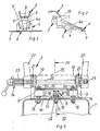
- the basic structure of the machine is generally known and comprises a machine frame 1, which in turn includes a motor unit 2, which serves, among other things, to drive the machine, a two-armed spar arrangement 3 with the usual operating elements for handling the entire machine and a main support 4 provided on the front of the frame with a cover 4a and with a wheel set 5.
- the main carrier 4 has at its front end an implement 6 for working on the ground or from its surface, which is preferably designed to be removable and as a result can be replaced by another implement.
- the motor 2 usually drives the implement 6 at the same time via a transmission, which has at least one tool and is also of the type that vertical and / or rolling vibrations occur during operation of the tool, which in addition to the motor vibrations also lead to additional vibrations Vibrations of the entire machine lead, the vibration plane is perpendicular to the longitudinal axis of the machine or the main support 4.
- Such an implement can be a cutter bar device, the construction of which is also generally known and is therefore not explained in detail.
- a device has e.g. a rotating drive part for the upper knife of the cutter bar 7, the drive part being responsible for oscillating vertical vibrations.
- other tools can also be considered, it being important in the context in question here that undesired vertical or comparable vibrations occur during their operation which have to be damped.
- the machine which is guided by hand but driven by the motor 2 for the time being, has a known PTO shaft which is connected to the drive shaft of the implement.
- the two shafts run within the main support 4, which is usually designed as a tubular support.
- the common axis of rotation of the two aforementioned shafts is intended as the longitudinal axis of the machine. Acting vertically and as a torque to this axis, oscillating vibration components are assumed which are triggered by the working tool 6 and by the drive motor 2.
- the beam arrangement 3 is oscillatory moderately decoupled to a certain extent from the rest of the machine by connecting the spar arrangement to the machine frame 1 via a hinge-like articulated connection 8 and by providing at least one damping element 9 horizontally laterally next to the articulated connection.
- the articulated connection 8 is arranged centrally between the spar arrangement 3 and the machine frame 1 in such a way that its hinge axis 10, about which the spar arrangement and the machine frame are movable relative to one another, extends at least substantially in the longitudinal direction of the machine.
- two damping elements 9 are provided at a distance laterally next to the articulated connection 8, one element on each side. Two or more elements can also be used on each page.
- the damping elements 9 are e.g. from known rubber buffers, e.g. are connected to the beam arrangement 3 by screw connections 9a, while the elements 9, on the other hand, are loosely supported on the upper section of the machine frame 1.
- the elements 9 can also be fastened to the machine frame while they lie loosely on the spar arrangement.
- the hinge-like hinge connection 8 consists of a middle sleeve 11, which is welded to the spar arrangement 3, two outer sleeves 12, which are welded to the machine frame 1, and a common hinge pin 13, which receives all sleeves.
- the upper and horizontally executed section la of the machine frame 1 has a screw connection 15 attached, elongated plate 14 to which in turn the middle sleeve 11 is welded.
- the spar arrangement 3 has a lower, in cross-section, for example, U-shaped cross member 16, on the underside of which an intermediate part 17 is welded, to which in turn the outer sleeves 12 are welded.
- the intermediate part 16 additionally has stop legs 18.
- the cross member 16 carries at both ends an end plate 19, which in turn are connected to each other by a spacer tube 20.
- the end plates 19 each have a pair of parts 21, the two parts of each pair using spur gearing, e.g. a Hirth serration, mesh with each other.
- a toothed part of the pairs of parts is in engagement with a guide bar 22 of the bar arrangement 3.
- the Hirth serration enables the guide rails 22 to be set as desired, which are determined by a threaded rod 23 being guided through the spacer tube 20, which interacts with a lever-like handle 24 which is actuated by turning in order to fix the guide rails 22.
- the spars 22 can also be welded to the end plates 19.
- a common hood 25 is provided, which is preferably connected to the machine frame 1 by means of a positive connection.
- the machine frame 1 has depressions 26 into which correspondingly curved edges 27 of the hood 25 snap. 4, the hood 25 can also serve that the hinge pin 13 of the hinge 8th is secured in its position.
Landscapes
- Engineering & Computer Science (AREA)
- Life Sciences & Earth Sciences (AREA)
- Environmental Sciences (AREA)
- Chemical & Material Sciences (AREA)
- Combustion & Propulsion (AREA)
- Transportation (AREA)
- Mechanical Engineering (AREA)
- Harvester Elements (AREA)
Applications Claiming Priority (2)
| Application Number | Priority Date | Filing Date | Title |
|---|---|---|---|
| DE19863629811 DE3629811A1 (de) | 1986-09-02 | 1986-09-02 | Handgefuehrte selbstfahrende maschine fuer die bodenbearbeitung |
| DE3629811 | 1986-09-02 |
Publications (3)
| Publication Number | Publication Date |
|---|---|
| EP0262425A2 true EP0262425A2 (fr) | 1988-04-06 |
| EP0262425A3 EP0262425A3 (en) | 1988-12-14 |
| EP0262425B1 EP0262425B1 (fr) | 1990-06-20 |
Family
ID=6308727
Family Applications (1)
| Application Number | Title | Priority Date | Filing Date |
|---|---|---|---|
| EP87112704A Expired - Lifetime EP0262425B1 (fr) | 1986-09-02 | 1987-09-01 | Machine automotrice pour le travail du sol menée par un conducteur marchant |
Country Status (2)
| Country | Link |
|---|---|
| EP (1) | EP0262425B1 (fr) |
| DE (2) | DE3629811A1 (fr) |
Cited By (2)
| Publication number | Priority date | Publication date | Assignee | Title |
|---|---|---|---|---|
| EP0477629A1 (fr) * | 1990-09-10 | 1992-04-01 | Agria-Werke Gmbh | Outil motorisé guidé à la main, avec poignée montée élastiquement |
| EP1075785A1 (fr) * | 1999-08-09 | 2001-02-14 | Honda Giken Kogyo Kabushiki Kaisha | Cultivateur de taille réduite |
Families Citing this family (2)
| Publication number | Priority date | Publication date | Assignee | Title |
|---|---|---|---|---|
| DE4007919A1 (de) * | 1990-03-13 | 1991-09-26 | Fraunhofer Ges Forschung | Schwingungsdaempfungsvorrichtung fuer vertikale schwingungen |
| EP2966955A4 (fr) | 2013-03-14 | 2016-11-23 | Husqvarna Ab | Isolation de vibration à double fonction et pivot de poignée |
Family Cites Families (4)
| Publication number | Priority date | Publication date | Assignee | Title |
|---|---|---|---|---|
| BE414757A (fr) * | 1935-04-25 | |||
| FR1254347A (fr) * | 1960-04-19 | 1961-02-17 | Dispositif pour raccorder les mancherons d'un tracteur à un seul essieu dirigé à la main au bloc-mécanisme de ce tracteur | |
| US4556203A (en) * | 1984-01-05 | 1985-12-03 | The Charles Stark Draper Laboratory, Inc. | Remote center compliance device |
| DE3503938A1 (de) * | 1985-02-06 | 1986-08-07 | Fraunhofer-Gesellschaft zur Förderung der angewandten Forschung e.V., 8000 München | Elastische griffholmen-lagerung fuer beidhaendig gefuehrte motorgeraete |
-
1986
- 1986-09-02 DE DE19863629811 patent/DE3629811A1/de active Granted
-
1987
- 1987-09-01 DE DE8787112704T patent/DE3763302D1/de not_active Expired - Lifetime
- 1987-09-01 EP EP87112704A patent/EP0262425B1/fr not_active Expired - Lifetime
Cited By (2)
| Publication number | Priority date | Publication date | Assignee | Title |
|---|---|---|---|---|
| EP0477629A1 (fr) * | 1990-09-10 | 1992-04-01 | Agria-Werke Gmbh | Outil motorisé guidé à la main, avec poignée montée élastiquement |
| EP1075785A1 (fr) * | 1999-08-09 | 2001-02-14 | Honda Giken Kogyo Kabushiki Kaisha | Cultivateur de taille réduite |
Also Published As
| Publication number | Publication date |
|---|---|
| DE3629811C2 (fr) | 1989-01-19 |
| DE3629811A1 (de) | 1988-03-10 |
| EP0262425B1 (fr) | 1990-06-20 |
| EP0262425A3 (en) | 1988-12-14 |
| DE3763302D1 (de) | 1990-07-26 |
Similar Documents
| Publication | Publication Date | Title |
|---|---|---|
| DE3447401C2 (fr) | ||
| DE3702221A1 (de) | Maehmaschine | |
| EP0073359A2 (fr) | Dispositif de verrouillage pour faucheuse | |
| EP0580088B1 (fr) | Outil d'ameublissement | |
| EP0262425B1 (fr) | Machine automotrice pour le travail du sol menée par un conducteur marchant | |
| EP0446681B1 (fr) | Dispositif amortisseur de vibrations pour oscillations verticales | |
| EP2940213B1 (fr) | Arbre de commande à oscillations découplées pour un outil de travail | |
| DE69520119T2 (de) | Gezogenes landwirtschaftliches Gerät | |
| DE3447400C2 (fr) | ||
| DE3116984C2 (fr) | ||
| EP0566033A1 (fr) | Cadre support pour machine de récolte, en particulier faucheuse rotative | |
| EP0229334B1 (fr) | Moissonneuse mobile, dirigée à la main | |
| DE2127091C3 (de) | Lenkfahrgestell für eine selbstfahrende Rüttelwalze | |
| DE3336533C2 (de) | Landwirtschaftliches motorbetriebenes Gerät | |
| EP0477629B1 (fr) | Outil motorisé guidé à la main, avec poignée montée élastiquement | |
| DE4027025A1 (de) | Heuwerbungsmaschine | |
| DE2755001C2 (fr) | ||
| DE3610140C2 (fr) | ||
| DE2412172C2 (fr) | ||
| DE19625732A1 (de) | Stabilisationsrahmen für Heuwerbungsmaschinen (Kreiselheuer) | |
| DE1507302B2 (de) | Maehmaschine | |
| EP0468138A1 (fr) | Suspension antérieur de motocyclette | |
| EP0046200B1 (fr) | Appareil pour le travail de la terre monté sur tracteur | |
| DE19901138B4 (de) | Arbeitsgerät für die Oberflächenbearbeitung von Wegen und Straßen | |
| AT392391B (de) | Antrieb fuer maehmesserbalken, insbesondere fuer einachsige, handgefuehrte motorgeraete |
Legal Events
| Date | Code | Title | Description |
|---|---|---|---|
| PUAI | Public reference made under article 153(3) epc to a published international application that has entered the european phase |
Free format text: ORIGINAL CODE: 0009012 |
|
| AK | Designated contracting states |
Kind code of ref document: A2 Designated state(s): CH DE FR IT LI |
|
| PUAL | Search report despatched |
Free format text: ORIGINAL CODE: 0009013 |
|
| AK | Designated contracting states |
Kind code of ref document: A3 Designated state(s): CH DE FR IT LI |
|
| 17P | Request for examination filed |
Effective date: 19890428 |
|
| 17Q | First examination report despatched |
Effective date: 19890825 |
|
| GRAA | (expected) grant |
Free format text: ORIGINAL CODE: 0009210 |
|
| AK | Designated contracting states |
Kind code of ref document: B1 Designated state(s): CH DE FR IT LI |
|
| PG25 | Lapsed in a contracting state [announced via postgrant information from national office to epo] |
Ref country code: FR Effective date: 19900620 |
|
| REF | Corresponds to: |
Ref document number: 3763302 Country of ref document: DE Date of ref document: 19900726 |
|
| ITF | It: translation for a ep patent filed | ||
| EN | Fr: translation not filed | ||
| PLBE | No opposition filed within time limit |
Free format text: ORIGINAL CODE: 0009261 |
|
| STAA | Information on the status of an ep patent application or granted ep patent |
Free format text: STATUS: NO OPPOSITION FILED WITHIN TIME LIMIT |
|
| 26N | No opposition filed | ||
| ITTA | It: last paid annual fee | ||
| PGFP | Annual fee paid to national office [announced via postgrant information from national office to epo] |
Ref country code: CH Payment date: 19970904 Year of fee payment: 11 |
|
| PGFP | Annual fee paid to national office [announced via postgrant information from national office to epo] |
Ref country code: DE Payment date: 19970924 Year of fee payment: 11 |
|
| PG25 | Lapsed in a contracting state [announced via postgrant information from national office to epo] |
Ref country code: LI Free format text: LAPSE BECAUSE OF NON-PAYMENT OF DUE FEES Effective date: 19980930 Ref country code: CH Free format text: LAPSE BECAUSE OF NON-PAYMENT OF DUE FEES Effective date: 19980930 |
|
| REG | Reference to a national code |
Ref country code: CH Ref legal event code: PL |
|
| PG25 | Lapsed in a contracting state [announced via postgrant information from national office to epo] |
Ref country code: DE Free format text: LAPSE BECAUSE OF NON-PAYMENT OF DUE FEES Effective date: 19990701 |
|
| PG25 | Lapsed in a contracting state [announced via postgrant information from national office to epo] |
Ref country code: IT Free format text: LAPSE BECAUSE OF NON-PAYMENT OF DUE FEES;WARNING: LAPSES OF ITALIAN PATENTS WITH EFFECTIVE DATE BEFORE 2007 MAY HAVE OCCURRED AT ANY TIME BEFORE 2007. THE CORRECT EFFECTIVE DATE MAY BE DIFFERENT FROM THE ONE RECORDED. Effective date: 20050901 |