EP0262425A2 - Powered soil-working machine controlled by a walking person - Google Patents
Powered soil-working machine controlled by a walking person Download PDFInfo
- Publication number
- EP0262425A2 EP0262425A2 EP87112704A EP87112704A EP0262425A2 EP 0262425 A2 EP0262425 A2 EP 0262425A2 EP 87112704 A EP87112704 A EP 87112704A EP 87112704 A EP87112704 A EP 87112704A EP 0262425 A2 EP0262425 A2 EP 0262425A2
- Authority
- EP
- European Patent Office
- Prior art keywords
- machine
- hinge
- connection
- machine frame
- arrangement
- Prior art date
- Legal status (The legal status is an assumption and is not a legal conclusion. Google has not performed a legal analysis and makes no representation as to the accuracy of the status listed.)
- Granted
Links
Images

Classifications
-
- B—PERFORMING OPERATIONS; TRANSPORTING
- B62—LAND VEHICLES FOR TRAVELLING OTHERWISE THAN ON RAILS
- B62D—MOTOR VEHICLES; TRAILERS
- B62D51/00—Motor vehicles characterised by the driver not being seated
- B62D51/001—Motor vehicles characterised by the driver not being seated characterised by the vehicle control device
-
- A—HUMAN NECESSITIES
- A01—AGRICULTURE; FORESTRY; ANIMAL HUSBANDRY; HUNTING; TRAPPING; FISHING
- A01D—HARVESTING; MOWING
- A01D34/00—Mowers; Mowing apparatus of harvesters
- A01D34/01—Mowers; Mowing apparatus of harvesters characterised by features relating to the type of cutting apparatus
- A01D34/02—Mowers; Mowing apparatus of harvesters characterised by features relating to the type of cutting apparatus having reciprocating cutters
- A01D34/08—Mowers; Mowing apparatus of harvesters characterised by features relating to the type of cutting apparatus having reciprocating cutters hand-guided by a walking operator
Definitions
- the invention relates to a hand-held, self-propelled machine for working the soil or its surface, in which a bar arrangement to be operated by an operator for guiding the machine is fastened to a machine frame via a connection which interacts with at least one damping means and which has a drive motor and at least one of carries the motor driven tool which works the floor area, the connection allowing a damped and limited rotary movement of the beam arrangement about the longitudinal axis of the machine.
- Such a machine is disclosed in DE 35 03 938 A1, in which the spar arrangement is connected to the rest of the machine by a connecting structure with a plurality of damping elements in the form of cylindrical, elastic rubber mounts, the omnidirectional rubber mounts functionally serving as an intermediate link between the spar arrangement and the form the rest of the machine, so that the one exerted by an operator on the beam arrangement Power flow, for example in order to change the working direction of the machine, must necessarily run through the rubber bearings.
- the damping property of the rubber bearings this means that the machine cannot be guided safely with the engine and driven implement running, particularly with regard to its cornering stability.
- the spar arrangement is thus spongy within the damping amplitudes of the rubber bearings, so that the rest of the machine cannot immediately react to changes in direction of the spar arrangement in accordance with the will of the operator. This is only the case when the axle body of the spar arrangement strikes a socket due to the maximum damping amplitude, which therefore only has a stop function.
- the object of the invention is to improve a machine of the type mentioned in such a way that, on the one hand, the good guiding ability of the machine is fully preserved both in its direction of travel and in its inclination and horizontal transverse movements, but on the other hand the vertical components of the engine and the Vibrations caused by him only reach the strut arrangement to be handled by the operator in a damped manner.
- connection mentioned consists of a hinge-like articulated connection and the damping means is provided with a horizontal radial distance from the hinge-like articulated connection between the spar arrangement and the machine frame.
- the hinge-like hinge connection consists of a middle sleeve, which is welded to the cross member of the spar arrangement, two outer sleeves axially adjoining the sleeve at both ends, which are welded to the machine frame, and a common hinge pin, which extends through all sleeves .
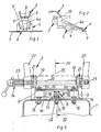
- the basic structure of the machine is generally known and comprises a machine frame 1, which in turn includes a motor unit 2, which serves, among other things, to drive the machine, a two-armed spar arrangement 3 with the usual operating elements for handling the entire machine and a main support 4 provided on the front of the frame with a cover 4a and with a wheel set 5.
- the main carrier 4 has at its front end an implement 6 for working on the ground or from its surface, which is preferably designed to be removable and as a result can be replaced by another implement.
- the motor 2 usually drives the implement 6 at the same time via a transmission, which has at least one tool and is also of the type that vertical and / or rolling vibrations occur during operation of the tool, which in addition to the motor vibrations also lead to additional vibrations Vibrations of the entire machine lead, the vibration plane is perpendicular to the longitudinal axis of the machine or the main support 4.
- Such an implement can be a cutter bar device, the construction of which is also generally known and is therefore not explained in detail.
- a device has e.g. a rotating drive part for the upper knife of the cutter bar 7, the drive part being responsible for oscillating vertical vibrations.
- other tools can also be considered, it being important in the context in question here that undesired vertical or comparable vibrations occur during their operation which have to be damped.
- the machine which is guided by hand but driven by the motor 2 for the time being, has a known PTO shaft which is connected to the drive shaft of the implement.
- the two shafts run within the main support 4, which is usually designed as a tubular support.
- the common axis of rotation of the two aforementioned shafts is intended as the longitudinal axis of the machine. Acting vertically and as a torque to this axis, oscillating vibration components are assumed which are triggered by the working tool 6 and by the drive motor 2.
- the beam arrangement 3 is oscillatory moderately decoupled to a certain extent from the rest of the machine by connecting the spar arrangement to the machine frame 1 via a hinge-like articulated connection 8 and by providing at least one damping element 9 horizontally laterally next to the articulated connection.
- the articulated connection 8 is arranged centrally between the spar arrangement 3 and the machine frame 1 in such a way that its hinge axis 10, about which the spar arrangement and the machine frame are movable relative to one another, extends at least substantially in the longitudinal direction of the machine.
- two damping elements 9 are provided at a distance laterally next to the articulated connection 8, one element on each side. Two or more elements can also be used on each page.
- the damping elements 9 are e.g. from known rubber buffers, e.g. are connected to the beam arrangement 3 by screw connections 9a, while the elements 9, on the other hand, are loosely supported on the upper section of the machine frame 1.
- the elements 9 can also be fastened to the machine frame while they lie loosely on the spar arrangement.
- the hinge-like hinge connection 8 consists of a middle sleeve 11, which is welded to the spar arrangement 3, two outer sleeves 12, which are welded to the machine frame 1, and a common hinge pin 13, which receives all sleeves.
- the upper and horizontally executed section la of the machine frame 1 has a screw connection 15 attached, elongated plate 14 to which in turn the middle sleeve 11 is welded.
- the spar arrangement 3 has a lower, in cross-section, for example, U-shaped cross member 16, on the underside of which an intermediate part 17 is welded, to which in turn the outer sleeves 12 are welded.
- the intermediate part 16 additionally has stop legs 18.
- the cross member 16 carries at both ends an end plate 19, which in turn are connected to each other by a spacer tube 20.
- the end plates 19 each have a pair of parts 21, the two parts of each pair using spur gearing, e.g. a Hirth serration, mesh with each other.
- a toothed part of the pairs of parts is in engagement with a guide bar 22 of the bar arrangement 3.
- the Hirth serration enables the guide rails 22 to be set as desired, which are determined by a threaded rod 23 being guided through the spacer tube 20, which interacts with a lever-like handle 24 which is actuated by turning in order to fix the guide rails 22.
- the spars 22 can also be welded to the end plates 19.
- a common hood 25 is provided, which is preferably connected to the machine frame 1 by means of a positive connection.
- the machine frame 1 has depressions 26 into which correspondingly curved edges 27 of the hood 25 snap. 4, the hood 25 can also serve that the hinge pin 13 of the hinge 8th is secured in its position.
Landscapes
- Engineering & Computer Science (AREA)
- Life Sciences & Earth Sciences (AREA)
- Environmental Sciences (AREA)
- Chemical & Material Sciences (AREA)
- Combustion & Propulsion (AREA)
- Transportation (AREA)
- Mechanical Engineering (AREA)
- Harvester Elements (AREA)
Abstract
Description
Die Erfindung betrifft eine handgeführte selbstfahrende Maschine für die Bearbeitung des Bodens oder seiner Oberfläche, bei der eine von einer Bedienungsperson zu handhabende Holmanordnung zur Führung der Maschine über eine mit wenigstens einem Dämpfungsmittel zusammenwirkende Verbindung an einem Maschinenrahmen befestigt ist, der einen Antriebsmotor und wenigstens ein von dem Motor angetriebenes, den Bodenbereich bearbeitendes Werkzeug trägt, wobei die Verbindung eine gedämpfte und begrenzte Drehbewegung der Holmanordnung um die Längsachse der Maschine gestattet.The invention relates to a hand-held, self-propelled machine for working the soil or its surface, in which a bar arrangement to be operated by an operator for guiding the machine is fastened to a machine frame via a connection which interacts with at least one damping means and which has a drive motor and at least one of carries the motor driven tool which works the floor area, the connection allowing a damped and limited rotary movement of the beam arrangement about the longitudinal axis of the machine.
In der DE 35 03 938 A1 ist eine derartige Maschine offenbart, bei der die Holmanordnung mit der übrigen Maschine durch eine Verbindungskonstruktion mit mehreren Dämpfungselementen in Form von zylindrischen, elastischen Gummilagern verbunden ist, wobei die allseitig wirkenden Gummilager funktionell ein Zwischenglied zwischen der Holmanordnung und der übrigen Maschine bilden, so daß der von einer Bedienungsperson auf die Holmanordnung ausgeübte Kraftfluß, z.B. zwecks Änderung der Arbeitsrichtung der Maschine, zwangsläufig über die Gummilager verlaufen muß. Daraus folgt in Verbindung mit der Dämpfungseigenschaft der Gummilager, daß die Maschine bei laufendem Motor und angetriebenem Arbeitsgerät nicht sicher geführt werden kann, insbesondere hinsichtlich ihrer Seitenführungsstabilität. Die Holmanordnung ist somit innerhalb der Dämpfungsamplituden der Gummilager schwammig gelagert, so daß durch die übrige Maschine nicht sofort auf Richtungsänderungen der Holmanordnung gemäß dem Willen der Bedienungsperson reagieren kann. Dies ist erst dann der Fall, wenn der Achskörper der Holmanordnung aufgrund der maximalen Dämpfungsamplitude an einer Buchse anschlägt, die somit nur Anschlagfunktion ausübt.Such a machine is disclosed in DE 35 03 938 A1, in which the spar arrangement is connected to the rest of the machine by a connecting structure with a plurality of damping elements in the form of cylindrical, elastic rubber mounts, the omnidirectional rubber mounts functionally serving as an intermediate link between the spar arrangement and the form the rest of the machine, so that the one exerted by an operator on the beam arrangement Power flow, for example in order to change the working direction of the machine, must necessarily run through the rubber bearings. In connection with the damping property of the rubber bearings, this means that the machine cannot be guided safely with the engine and driven implement running, particularly with regard to its cornering stability. The spar arrangement is thus spongy within the damping amplitudes of the rubber bearings, so that the rest of the machine cannot immediately react to changes in direction of the spar arrangement in accordance with the will of the operator. This is only the case when the axle body of the spar arrangement strikes a socket due to the maximum damping amplitude, which therefore only has a stop function.
Die Aufgabe der Erfindung besteht in der Verbesserung einer Maschine der einleitend angeführten Art dahingehend, daß einerseits die gute Führungsfähigkeit der Maschine sowohl in deren Fahrrichtung als auch bei deren Neigungsund horizontalen Querbewegungen voll erhalten bleibt, daß aber andererseits die Vertikalkomponenten der durch den Motor und das von ihm angetriebene Werkzeug hervorgerufenen Vibrationen nur gedämpft auf die von der Bedienungsperson zu handhabende Holmanordnung gelangen.The object of the invention is to improve a machine of the type mentioned in such a way that, on the one hand, the good guiding ability of the machine is fully preserved both in its direction of travel and in its inclination and horizontal transverse movements, but on the other hand the vertical components of the engine and the Vibrations caused by him only reach the strut arrangement to be handled by the operator in a damped manner.
In bevorzugter Ausgestaltung der erfindungsgemäßen Maschine besteht die erwähnte Verbindung aus einer scharnierartigen Gelenkverbindung und das Dämpfungsmittel ist mit horizontalem radialem Abstand von der scharnierartigen Gelenkverbindung zwischen der Holmanordnung und dem Maschinenrahmen wirkend vorgesehen.In a preferred embodiment of the machine according to the invention, the connection mentioned consists of a hinge-like articulated connection and the damping means is provided with a horizontal radial distance from the hinge-like articulated connection between the spar arrangement and the machine frame.
In bevorzugter Ausgestaltung der erfindungsgemäßen Ma schine besteht die scharnierartige Gelenkverbindung aus einer mittleren Hülse, die mit dem Traversenteil der Holmanordnung verschweißt ist, aus zwei äußeren, sich beidendig an die Hülse axial anschließenden Hülsen, die mit dem Maschinenrahmen verschweißt sind, und aus einem gemeinsamen, sich durch alle Hülsen erstreckenden Gelenkbolzen.In a preferred embodiment of the Ma The hinge-like hinge connection consists of a middle sleeve, which is welded to the cross member of the spar arrangement, two outer sleeves axially adjoining the sleeve at both ends, which are welded to the machine frame, and a common hinge pin, which extends through all sleeves .
Durch diese Lösung bleibt die Führungsfähigkeit der Maschine in jeder Richtung, insbesondere in horizontaler seitlicher Richtung, und in jedem Augenblick voll erhalten, da die scharnierartige Gelenkverbindung, abgesehen von ihrer Beweglichkeit um die eigene Achse, als starre Verbindung anzusehen ist. Die Steuerungsbewegungen der Bedienungsperson werden somit ohne Verzögerung oder Abweichung genau auf die übrige Maschine übertragen, weil der Kraftfluß allein über diese scharnierartige Gelenkverbindung verläuft. Gleichzeitig erfolgt aber eine sehr beträchtliche Dämpfung der vom Arbeitswerkzeug und vom Motor der Maschine ausgehenden, um die horizontale Längsachse der Maschine wirksamen vertikalen Vibrationen aufgrund der Dämpfungsmittel zu der scharnierartigen Gelenkverbindung. Ferner sind die Dämpfungsmittel von jeder zur Führung der Maschine erforderlichen Krafteinwirkung durch die Bedienungsperson entlastet und werden dadurch geschont.With this solution, the guiding ability of the machine is fully preserved in every direction, in particular in the horizontal lateral direction, and at every moment, since the hinge-like articulated connection, apart from its mobility around its own axis, can be regarded as a rigid connection. The control movements of the operator are thus transferred to the rest of the machine without delay or deviation, because the power flow runs solely via this hinge-like articulation. At the same time, however, there is a very considerable damping of the vertical vibrations emanating from the work tool and from the engine of the machine and effective about the horizontal longitudinal axis of the machine due to the damping means to the hinge-like articulation. Furthermore, the damping means are relieved of any force required by the operator to guide the machine and are thus protected.
In diesem Zusammenhang sei erwähnt, daß der Motor, der sowohl die Maschine selbst als auch das Werkzeug antreibt, im allgemeinen selbst gedämpft auf dem Maschinenrahmen abgestützt ist und daß für die Dämpfung der horizontal wirkenden Komponenten der Werkzeugschwingungen unterschiedliche Lösungen bekannt sind. Diese Lösungen wirken in anderen Bereichen als an der Stelle der Verbindung der Holmanordnung mit der übrigen Maschine. Soweit also Horizontalschwingungen betroffen sind, werden diese durch derartige Lösungen gedämpft.In this connection it should be mentioned that the motor, which drives both the machine itself and the tool, is generally supported in a damped manner on the machine frame and that different solutions are known for damping the horizontally acting components of the tool vibrations. These solutions work in areas other than where the spar assembly is connected to the rest of the machine. As far as horizontal vibrations are concerned, they are dampened by such solutions.
Die Erfindung ist nachstehend anhand eines in den anliegenden Zeichnungen dargestellten Ausführungsbeispieles näher erläutert. Es zeigen:
Figur 1 eine Vorderansicht auf das Ausführungsbeispiel,Figur 2 eine Seitenansicht auf das Ausführungsbeispiel,- Figur 3 die Einzelheit X in Fig. 1 in vergrößertem Maßstab,
Figur 4 eine Schnittdarstellung gemäß der Linie IV - IV in Fig. 3 in einem noch größeren Maßstab.
- FIG. 1 shows a front view of the exemplary embodiment,
- FIG. 2 shows a side view of the exemplary embodiment,
- FIG. 3 shows the detail X in FIG. 1 on an enlarged scale,
- Figure 4 is a sectional view along the line IV - IV in Fig. 3 on an even larger scale.
Der grundsätzliche Aufbau der Maschine ist allgemein bekannt und umfaßt einen Maschinenrahmen 1, der wiederum eine Motoreinheit 2, die u.a. als Fahrantrieb der Maschine dient, eine zweiarmige Holmanordnung 3 mit den üblichen Bedienungselementen zur Handhabung der gesamten Maschine und einen vorn an dem Rahmen vorgesehenen Hauptträger 4 mit einer Abdeckhaube 4a und mit einem Radsatz 5 trägt. Der Hauptträger 4 weist an seinem Vorderende ein Arbeitsgerät 6 zur Bearbeitung des Erdbodens oder von dessen Oberfläche auf, das vorzugsweise abnehmbar ausgebildet ist und infolgedessen durch ein anderes Arbeitsgerät ersetzt werden kann. Der Motor 2 treibt üblicherweise über ein Getriebe auch gleichzeitig das Arbeitsgerät 6 an, das wenigstens ein Werkzeug aufweist und ferner von der Art ist, daß beim Betrieb des Werkzeuges unter anderem vertikale und/oder rollende Schwingungen auftreten, die neben den Motorvibrationen zu zusätzlichen Vibrationen der gesamten Maschine führen, deren Schwingungsebene senkrecht zur Längsachse der Maschine bzw. des Hauptträgers 4 liegt.The basic structure of the machine is generally known and comprises a
Ein derartiges Arbeitsgerät kann eine Mähbalkenvorrichtung sein, deren Aufbau ebenfalls allgemein bekannt und deshalb im einzelnen nicht näher erläutert ist. Eine solche Vorrichtung hat z.B. ein rotierendes Antriebsteil für das Obermesser des Mähbalkens 7, wobei das Antriebsteil für oszillierende Vertikalschwingungen verantwortlich ist. Es können jedoch auch andere Werkzeuge in Betracht kommen, wobei in dem hier fraglichen Zusammenhang wichtig ist, daß bei deren Betrieb unerwünschte vertikale oder vergleichbare Schwingungen auftreten, die zu dämpfen sind.Such an implement can be a cutter bar device, the construction of which is also generally known and is therefore not explained in detail. Such a device has e.g. a rotating drive part for the upper knife of the
Die von Hand geführte, jedoch von dem Motor 2 vorwährts angetriebene Maschine besitzt eine bekannte Zapfwelle, die mit der Antriebswelle des Arbeitsgerätes verbunden ist. Die beiden Wellen verlaufen innerhalb des üblicherweise als Rohrträger ausgebildeten Hauptträgers 4.The machine, which is guided by hand but driven by the
Zum leichteren Verständnis des vorgeschlagenen Lösungsprinzips sei die gemeinsame Drehachse der beiden vorgenannten Wellen als Längsachse der Maschine gedacht. Vertikal und als Drehmoment zu dieser Achse wirkend seien oszillierende Schwingungskomponenten angenommen, die vom arbeitenden Werkzeug 6 und von dem Antriebsmotor 2 ausgelöst werden.For easier understanding of the proposed solution principle, the common axis of rotation of the two aforementioned shafts is intended as the longitudinal axis of the machine. Acting vertically and as a torque to this axis, oscillating vibration components are assumed which are triggered by the
Um die entsprechenden oszillierenden Schwingungen bzw. Vibrationen der Holmanordnung zu dämpfen, dabei aber die gesamte Führungsfähigkeit der Maschine sowohl in Fahrrichtung als auch hinsichtlich ihrer Neigungs- und Querbewegungen zu erhalten, ist die Holmanordnung 3 schwingungs mäßig in gewissem Umfang von der übrigen Maschine abgekoppelt, indem die Holmanordnung über eine scharnierartige Gelenkverbindung 8 mit dem Maschinenrahmen 1 verbunden und indem horizontal seitlich neben der Gelenkverbindung wenigstens ein Dämpfungselement 9 vorgesehen ist. Die Gelenkverbindung 8 ist mittig so zwischen der Holmanordnung 3 und dem Maschinenrahmen 1 angeordnet, daß sich ihre Gelenkachse 10, um die die Holmanordnung und der Maschinenrahmen zueinander beweglich sind, wenigstens im wesentlichen in Längsrichtung der Maschine erstreckt. Wie es am besten aus Fig. 3 zu erkennen ist, sind zwei Dämpfungselemente 9 mit Abstand seitlich neben der Gelenkverbindung 8 vorgesehen, und zwar je ein Element auf jeder Seite. Es können auch zwei oder mehr Elemente auf jeder Seite verwendet werden.In order to dampen the corresponding oscillating oscillations or vibrations of the beam arrangement, but to maintain the overall guidability of the machine both in the direction of travel and with regard to its inclination and transverse movements, the beam arrangement 3 is oscillatory moderately decoupled to a certain extent from the rest of the machine by connecting the spar arrangement to the
Die Dämpfungselemente 9 bestehen z.B. aus bekannten Gummipuffern, die z.B. mit der Holmanordnung 3 durch Verschraubungen 9a verbunden sind, während sich die Elemente 9 andererseits lose auf dem oberen Abschnitt des Maschinenrahmens 1 abstützen. Alternativ ist es natürlich möglich, daß die Elemente 9 auch an dem Maschinenrahmen befestigt sein können, während sie lose an der Holmanordnung enliegen.The
Gemäß den Figuren 3 und 4 besteht die scharnierartige Gelenkverbindung 8 aus einer mittleren Hülse 11, die mit der Holmanordnung 3 verschweißt ist, aus zwei äußeren Hülsen 12, die mit dem Maschinenrahmen 1 verschweißt sind, und aus einem gemeinsamen, alle Hülsen aufnehmenden Gelenkbolzen 13.According to FIGS. 3 and 4, the hinge-
Der obere und horizontal ausgeführte Abschnitt la des Maschinenrahmens 1 besitzt eine durch Verschraubungen 15 angebrachte, längliche Platte 14, an der wiederum die mittlere Hülse 11 angeschweißt ist.The upper and horizontally executed section la of the
Die Holmanordnung 3 besitzt ein unteres, im Querschnitt zum Beispiel U-förmiges Traversenteil 16, an dessen Unterseite ein Zwischenteil 17 angeschweißt ist, an dem wiederum die äußeren Hülsen 12 angeschweißt sind. Das Zwischenteil 16 weist zusätzlich Anschlagschenkel 18 auf.The spar arrangement 3 has a lower, in cross-section, for example, U-shaped
DasTraversenteil 16 trägt an seinen beiden Enden je eine Endplatte 19, die wiederum durch ein Distanzrohr 20 miteinander verbunden sind. An ihren Außenseiten weisen die Endplatten 19 je ein Teilepaar 21 auf, wobei die beiden Teile jedes Paares mittels einer Stirnverzahnung, z.B. eine Hirth-Verzahnung, miteinander in Eingriff stehen. Jeweils ein verzahntes Teil der Teilepaare steht mit einem Führungsholm 22 der Holmanordnung 3 in Eingriff. Die Hirth-Verzahnung ermöglicht eine gewünschte Einstellung der Führungsholme 22, die dadurch festgestellt werden, daß eine Gewindestange 23 durch das Distanzrohr 20 geführt ist, die mit einer hebelartigen Handhabe 24 zusammenwirkt, die durch Drehen betätigt wird, um die Führungsholme 22 festzustellen. Alternativ können die Holme 22 auch an den Endplatten 19 angeschweißt sein.The
Zum Schutz der Gelenkverbindung 8, der Dämpfungselemente 9 und wenigstens des Traversenteiles 16 ist eine gemeinsame Haube 25 vorgesehen, die vorzugsweise mittels Formschluß mit dem Maschinenrahmen 1 verbunden ist. Hierzu weist der Maschinenrahmen 1 Vertiefungen 26 auf, in welche entsprechend gebogene Ränder 27 der Haube 25 einschnappen. Gemäß Fig. 4 kann die Haube 25 auch dazu dienen, daß der Gelenkbolzen 13 der Gelenkverbindung 8 in seiner Lage gesichert ist.To protect the articulated
Claims (4)
Applications Claiming Priority (2)
| Application Number | Priority Date | Filing Date | Title |
|---|---|---|---|
| DE19863629811 DE3629811A1 (en) | 1986-09-02 | 1986-09-02 | HAND-DRIVED SELF-DRIVING MACHINE FOR TILLAGE TREATMENT |
| DE3629811 | 1986-09-02 |
Publications (3)
| Publication Number | Publication Date |
|---|---|
| EP0262425A2 true EP0262425A2 (en) | 1988-04-06 |
| EP0262425A3 EP0262425A3 (en) | 1988-12-14 |
| EP0262425B1 EP0262425B1 (en) | 1990-06-20 |
Family
ID=6308727
Family Applications (1)
| Application Number | Title | Priority Date | Filing Date |
|---|---|---|---|
| EP87112704A Expired - Lifetime EP0262425B1 (en) | 1986-09-02 | 1987-09-01 | Powered soil-working machine controlled by a walking person |
Country Status (2)
| Country | Link |
|---|---|
| EP (1) | EP0262425B1 (en) |
| DE (2) | DE3629811A1 (en) |
Cited By (2)
| Publication number | Priority date | Publication date | Assignee | Title |
|---|---|---|---|---|
| EP0477629A1 (en) * | 1990-09-10 | 1992-04-01 | Agria-Werke Gmbh | Hand-guided motor tool with elastically mounted handle |
| EP1075785A1 (en) * | 1999-08-09 | 2001-02-14 | Honda Giken Kogyo Kabushiki Kaisha | Small-sized tiller |
Families Citing this family (2)
| Publication number | Priority date | Publication date | Assignee | Title |
|---|---|---|---|---|
| DE4007919A1 (en) * | 1990-03-13 | 1991-09-26 | Fraunhofer Ges Forschung | VIBRATION DAMPING DEVICE FOR VERTICAL VIBRATIONS |
| EP2966955A4 (en) | 2013-03-14 | 2016-11-23 | Husqvarna Ab | Dual function vibration isolation and handle swivel |
Family Cites Families (4)
| Publication number | Priority date | Publication date | Assignee | Title |
|---|---|---|---|---|
| BE414757A (en) * | 1935-04-25 | |||
| FR1254347A (en) * | 1960-04-19 | 1961-02-17 | Device for connecting the handlebars of a single-axle tractor steered by hand to the mechanism block of this tractor | |
| US4556203A (en) * | 1984-01-05 | 1985-12-03 | The Charles Stark Draper Laboratory, Inc. | Remote center compliance device |
| DE3503938A1 (en) * | 1985-02-06 | 1986-08-07 | Fraunhofer-Gesellschaft zur Förderung der angewandten Forschung e.V., 8000 München | Elastic handle support for motor apparatuses which are controlled by both hands |
-
1986
- 1986-09-02 DE DE19863629811 patent/DE3629811A1/en active Granted
-
1987
- 1987-09-01 DE DE8787112704T patent/DE3763302D1/en not_active Expired - Lifetime
- 1987-09-01 EP EP87112704A patent/EP0262425B1/en not_active Expired - Lifetime
Cited By (2)
| Publication number | Priority date | Publication date | Assignee | Title |
|---|---|---|---|---|
| EP0477629A1 (en) * | 1990-09-10 | 1992-04-01 | Agria-Werke Gmbh | Hand-guided motor tool with elastically mounted handle |
| EP1075785A1 (en) * | 1999-08-09 | 2001-02-14 | Honda Giken Kogyo Kabushiki Kaisha | Small-sized tiller |
Also Published As
| Publication number | Publication date |
|---|---|
| DE3629811C2 (en) | 1989-01-19 |
| DE3629811A1 (en) | 1988-03-10 |
| EP0262425B1 (en) | 1990-06-20 |
| EP0262425A3 (en) | 1988-12-14 |
| DE3763302D1 (en) | 1990-07-26 |
Similar Documents
| Publication | Publication Date | Title |
|---|---|---|
| DE3447401C2 (en) | ||
| DE3702221A1 (en) | MOWER | |
| EP0073359A2 (en) | Locking device for a mowing machine | |
| EP0580088B1 (en) | Grubber | |
| EP0262425B1 (en) | Powered soil-working machine controlled by a walking person | |
| EP0446681B1 (en) | Vibration damping arrangement for vertical oscillations | |
| EP2940213B1 (en) | Vibration decoupled guidance drawbar for a work tool | |
| DE69520119T2 (en) | Drawn agricultural equipment | |
| DE3447400C2 (en) | ||
| DE3116984C2 (en) | ||
| EP0566033A1 (en) | Supporting frame for agricultural harvesting machine, particularly circular mower | |
| EP0229334B1 (en) | Mobile mowing machine, guided by hand | |
| DE2127091C3 (en) | Steering chassis for a self-propelled vibrating roller | |
| DE3336533C2 (en) | Agricultural motor-operated device | |
| EP0477629B1 (en) | Hand-guided motor tool with elastically mounted handle | |
| DE4027025A1 (en) | Rotary haymaking machine with travel unit - has stabilised arms for suspension of wheels | |
| DE2755001C2 (en) | ||
| DE3610140C2 (en) | ||
| DE2412172C2 (en) | ||
| DE19625732A1 (en) | Stabiliser frame for rotary hay making machine | |
| DE1507302B2 (en) | MOWER | |
| EP0468138A1 (en) | Front wheel suspension for motorcycle | |
| EP0046200B1 (en) | Soil-working implement mounted on a tractor | |
| DE19901138B4 (en) | Tool for surface treatment of roads and roads | |
| AT392391B (en) | DRIVE FOR MEASURING KNIFE BARS, ESPECIALLY FOR ONE-AXLE, MANUAL MOTORIZED EQUIPMENT |
Legal Events
| Date | Code | Title | Description |
|---|---|---|---|
| PUAI | Public reference made under article 153(3) epc to a published international application that has entered the european phase |
Free format text: ORIGINAL CODE: 0009012 |
|
| AK | Designated contracting states |
Kind code of ref document: A2 Designated state(s): CH DE FR IT LI |
|
| PUAL | Search report despatched |
Free format text: ORIGINAL CODE: 0009013 |
|
| AK | Designated contracting states |
Kind code of ref document: A3 Designated state(s): CH DE FR IT LI |
|
| 17P | Request for examination filed |
Effective date: 19890428 |
|
| 17Q | First examination report despatched |
Effective date: 19890825 |
|
| GRAA | (expected) grant |
Free format text: ORIGINAL CODE: 0009210 |
|
| AK | Designated contracting states |
Kind code of ref document: B1 Designated state(s): CH DE FR IT LI |
|
| PG25 | Lapsed in a contracting state [announced via postgrant information from national office to epo] |
Ref country code: FR Effective date: 19900620 |
|
| REF | Corresponds to: |
Ref document number: 3763302 Country of ref document: DE Date of ref document: 19900726 |
|
| ITF | It: translation for a ep patent filed | ||
| EN | Fr: translation not filed | ||
| PLBE | No opposition filed within time limit |
Free format text: ORIGINAL CODE: 0009261 |
|
| STAA | Information on the status of an ep patent application or granted ep patent |
Free format text: STATUS: NO OPPOSITION FILED WITHIN TIME LIMIT |
|
| 26N | No opposition filed | ||
| ITTA | It: last paid annual fee | ||
| PGFP | Annual fee paid to national office [announced via postgrant information from national office to epo] |
Ref country code: CH Payment date: 19970904 Year of fee payment: 11 |
|
| PGFP | Annual fee paid to national office [announced via postgrant information from national office to epo] |
Ref country code: DE Payment date: 19970924 Year of fee payment: 11 |
|
| PG25 | Lapsed in a contracting state [announced via postgrant information from national office to epo] |
Ref country code: LI Free format text: LAPSE BECAUSE OF NON-PAYMENT OF DUE FEES Effective date: 19980930 Ref country code: CH Free format text: LAPSE BECAUSE OF NON-PAYMENT OF DUE FEES Effective date: 19980930 |
|
| REG | Reference to a national code |
Ref country code: CH Ref legal event code: PL |
|
| PG25 | Lapsed in a contracting state [announced via postgrant information from national office to epo] |
Ref country code: DE Free format text: LAPSE BECAUSE OF NON-PAYMENT OF DUE FEES Effective date: 19990701 |
|
| PG25 | Lapsed in a contracting state [announced via postgrant information from national office to epo] |
Ref country code: IT Free format text: LAPSE BECAUSE OF NON-PAYMENT OF DUE FEES;WARNING: LAPSES OF ITALIAN PATENTS WITH EFFECTIVE DATE BEFORE 2007 MAY HAVE OCCURRED AT ANY TIME BEFORE 2007. THE CORRECT EFFECTIVE DATE MAY BE DIFFERENT FROM THE ONE RECORDED. Effective date: 20050901 |