EP0261580B1 - Steuervorrichtung - Google Patents
Steuervorrichtung Download PDFInfo
- Publication number
- EP0261580B1 EP0261580B1 EP87113559A EP87113559A EP0261580B1 EP 0261580 B1 EP0261580 B1 EP 0261580B1 EP 87113559 A EP87113559 A EP 87113559A EP 87113559 A EP87113559 A EP 87113559A EP 0261580 B1 EP0261580 B1 EP 0261580B1
- Authority
- EP
- European Patent Office
- Prior art keywords
- disc
- control device
- guide strip
- lateral guides
- slide element
- Prior art date
- Legal status (The legal status is an assumption and is not a legal conclusion. Google has not performed a legal analysis and makes no representation as to the accuracy of the status listed.)
- Expired - Lifetime
Links
- 229920003023 plastic Polymers 0.000 claims description 3
- 239000004033 plastic Substances 0.000 claims description 3
- 239000000463 material Substances 0.000 claims 1
- 238000006073 displacement reaction Methods 0.000 abstract description 2
- 238000000465 moulding Methods 0.000 description 3
- 230000007423 decrease Effects 0.000 description 1
- 238000011161 development Methods 0.000 description 1
- 230000018109 developmental process Effects 0.000 description 1
- 238000004519 manufacturing process Methods 0.000 description 1
- 239000002245 particle Substances 0.000 description 1
- 238000007493 shaping process Methods 0.000 description 1
- 238000004804 winding Methods 0.000 description 1
Images
Classifications
-
- A—HUMAN NECESSITIES
- A47—FURNITURE; DOMESTIC ARTICLES OR APPLIANCES; COFFEE MILLS; SPICE MILLS; SUCTION CLEANERS IN GENERAL
- A47L—DOMESTIC WASHING OR CLEANING; SUCTION CLEANERS IN GENERAL
- A47L9/00—Details or accessories of suction cleaners, e.g. mechanical means for controlling the suction or for effecting pulsating action; Storing devices specially adapted to suction cleaners or parts thereof; Carrying-vehicles specially adapted for suction cleaners
- A47L9/28—Installation of the electric equipment, e.g. adaptation or attachment to the suction cleaner; Controlling suction cleaners by electric means
- A47L9/2836—Installation of the electric equipment, e.g. adaptation or attachment to the suction cleaner; Controlling suction cleaners by electric means characterised by the parts which are controlled
- A47L9/2842—Suction motors or blowers
Definitions
- the invention relates to a control device according to the preamble of claim 1.
- the invention thus relates in particular to a control device for the drive motor of a vacuum cleaner, but it is also suitable for controlling other electrical or mechanical components.
- the electrical components are usually combined on a printed circuit board, an annular potentiometer being soldered to the underside of the circuit board.
- This ring-shaped potentiometer controls the power of the drive motor and for this purpose is penetrated by the control axis of a generally circular disk, at the other end of which a rotary knob can be arranged.
- the potentiometer can thus be adjusted by means of the rotary movement transmitted to the circular disk by the rotary knob and thus the motor power can be controlled.
- the rotation is usually about 270 °.
- the present invention has for its object to develop a control device of the type under consideration so that it is space-saving and also works reliably over a long service life.
- the control device should be cheap to produce as a mass part.
- the control device has a flexible guide band which is formed on the outer circumference of the circular disk and is provided with a slide element at the free end.
- the guide band is arranged between lateral guides and has such a rigidity that it rotates when the slide element is advanced in the direction of the disk and is wound on its circumference.
- the slide element is moved in the opposite direction, the disk is correspondingly rotated in the reverse direction, the guide band being unwound again from the periphery of the disk.
- the side guides prevent the guide band from evading when it is wound up on the circumference of the disk, a suitable space remaining between the lateral guides and the guide band, so that practically no frictional forces make the movement of the slide element difficult.
- the circular disc and the guide band are made in one piece from a suitable plastic, the manufacturing costs being extremely low.
- the slide element can also be integrally formed on the guide band.
- the circular disc with the molded guide band is practically indestructible, so that the control device according to the invention can function properly even over a long service life of the associated vacuum cleaner.
- Another advantage is that, depending on the size of the radius of the circular disc, the size of the sliding path of the slide element can be changed. If only a small sliding path is available, there will be a small radius chosen for the disc, so that even a small displacement of the slide element rotates the disc by a relatively large angle. With a larger radius of the disk, the angle of rotation decreases for a given length of the sliding path, so that a slower rotary movement takes place.
- the circular disc is arranged on a plate which is penetrated by the control axis of the disc and has the lateral guides for the guide band. This plate is placed on the electrical circuit board of the vacuum cleaner.
- the lateral guides for the guide band have a rectilinear section which contains the sliding path of the sliding element, and stops can be provided to limit the sliding path.
- This rectilinear guide section can run essentially tangentially to the circular disk, but it can also merge into an arcuate section which runs to the circumference of the circular disk if it has a reduced diameter given the predefined position of the rectilinear section and the control axis.
- the lateral guides can also at least partially encompass the outer circumference of the disk at a suitable distance, which makes it easier to wind up the tape, which can therefore not deflect laterally.
- the lateral guides for the guide band are expediently formed by webs arranged on the plate.
- the outer web of the guide can be formed continuously and additionally slidably receive the slide element for guiding it. To do this the slide element has a groove on its underside, in which the web is received with little play.
- the guide for the guide band can be formed by short, spaced webs.
- the slide element can be designed directly as an operating button and protrude through a guide slot in the vacuum cleaner housing into its interior.
- the slider element can also be overlapped by a fork of a separate slider button, in which case the slider element can be integrally formed on the belt.
- the slide button should have an elongated shape, which is selected so that the associated guide slot in the vacuum cleaner housing is always covered, so that no foreign particles can enter the interior of the housing through the guide slot.
- the circular disk expediently has a cut-away section in the region of the starting point of the guide band, which section serves as free space for a molding tool for shaping the band.
- the control device contains a circular disk 1 which is provided with a control axis 2 which engages in a potentiometer (not shown) and adjusts it when it rotates, thereby controlling the output of a drive motor.
- a flexible control band 3 is formed on the disc 1 and a slide element 4 is located at the free end thereof.
- the slider element 4 is a molded part with two parallel webs 5, which are overlapped by a fork of a slider button, also not shown.
- a section 7 is cut away from the circular disk 1, which creates a free space for a molding tool for molding the guide band 3.
- a plate 8 which receives the disc 1, wherein the control axis 2 of the disc 1 passes through a bore 9 of the plate 8.
- the plate 8 is in turn placed on a printed switch plate, not shown, on the underside of which is the potentiometer in which the control axis 2 engages.
- the plate 8 contains an elongated web 10 with a rectilinear section 11 and an approximately semicircular section 12 as well as short webs 13 arranged at a distance from the section 11. These webs form lateral guides for the guide band 3, which therefore cannot deflect laterally.
- the slide element 4 (Fig. 1) contains on its underside a groove 14 which is slightly wider than the web 11, so that the slide element 4 can be slidably placed on the web 11. At the end of the web 11 there is a stop 15 for the slide element 4.
- the slide element 4 is moved along the straight guide section 11 to adjust the potentiometer (not shown).
- the guide band 3 which is flexible but relatively stiff, rotates the disc 1 in the direction of arrow A (FIG. 1), the guide band 3 winding onto the circumference of the disc 1 because it can neither laterally deflect between the webs 11 and 13 of the straight guide section nor between the circumference of the disk 1 and the circular-arch-shaped web 12 which is slightly spaced from the circumference of the disk 1.
- the slide element 4 moves in the opposite direction, the direction of rotation of the disk 1 changes accordingly, the guide band 3 being unwound from the circumference of the disk 1.
Landscapes
- Engineering & Computer Science (AREA)
- Mechanical Engineering (AREA)
- Electric Vacuum Cleaner (AREA)
- Nozzles For Electric Vacuum Cleaners (AREA)
- Crystals, And After-Treatments Of Crystals (AREA)
- Vehicle Body Suspensions (AREA)
- Polarising Elements (AREA)
- Mechanical Control Devices (AREA)
Description
- Die Erfindung betrifft eine Steuervorrichtung gemäß dem Oberbegriff des Anspruchs 1. Damit betrifft die Erfindung insbesondere eine Steuervorrichtung für den Antriebsmotor eines Staubsaugers, sie ist jedoch ebenso zur Steuerung anderer elektrischer oder mechanischer Bauteile geeignet.
- Bei einem Staubsauger sind üblicherweise die elektrischen Bauteile auf einer gedruckten Leiterplatte zusammengefaßt, wobei an der Unterseite der Leiterplatte ein ringförmiges Potentiometer angelötet ist. Dieses ringförmige Potentiometer steuert die Leistung des Antriebsmotors und wird hierzu von der Steuerachse einer im allgemeinen kreisförmigen Scheibe durchgriffen, an deren anderen Ende ein Drehknopf angeordnet sein kann. Mittels der durch den Drehknopf auf die kreisförmige Scheibe übertragenen Drehbewegung läßt sich somit das Potentiometer verstellen und damit die Motorleistung steuern. Die Drehbewegung beträgt üblicherweise etwa 270°.
- Bei Bodenstaubsaugern ist häufig eine Steuervorrichtung anzutreffen, die anstelle eines Drehknopfes einen Schieberknopf verwendet, wobei diese Ausbildung den Vorteil hat, daß der entlang einer geradlinigen Bahn bewegbare Schieberknopf von dem Fuß einer Bedienungsperson betätigt werden kann, wodurch die Handhabung des Bodenstaubsaugers erleichtert ist. Dabei wird die geradlinige Bewegung des Schieberknopfes durch eine Zahnstange in eine Drehbewegung eines Zahnrades umgesetzt, die die mit der Steuerachse versehene Scheibe bildet. Die Zahnstange bewegt sich an dem ortsfest gelagerten Zahnrad vorbei, wobei diese Ausbildung den Nachteil hat, daß hinter dem Zahnrad Platz für die Aufnahme der Zahnstange vorgesehen sein muß. Außerdem können die Zähne der Zahnstange und des Zahnrades, die überlicherweise aus Kunststoff bestehen, im Laufe einer längeren Nutzungsdauer so abgenutzt werden, daß die Steuervorrichtung nicht mehr fehlerlos funktioniert.
- Der vorliegenden Erfindung liegt die Aufgabe zugrunde, eine Steuervorrichtung der betrachteten Art so weiter zu entwickeln, daß sie platzsparend ist und auch über eine lange Nutzungsdauer zuverlässig arbeitet. Darüberhinaus soll die Steuervorrichtung als Massenteil billig herstellbar sein.
- Diese Aufgabe wird erfindungsgemäß durch die im Kennzeichen des Anspruchs 1 genannten Merkmale gelöst. Vorteilhafte Weiterbildungen der Erfindung sind in den Unteransprüchen gekennzeichnet.
- Die erfindungsgemäße Steuervorrichtung hat ein flexibles Führungsband, das am Außenumfang der kreisförmigen Scheibe angeformt und an dem freien Ende mit einem Schieberelement versehen ist. Das Führungsband ist zwischen seitlichen Führungen angeordnet und weist eine solche Steifigkeit auf, daß es beim Vorschub des Schieberelementes in Richtung der Scheibe diese dreht und auf deren Umfang aufgewickelt wird. Bei der Bewegung des Schieberelementes in entgegengesetzter Richtung wird die Scheibe entsprechend in Umkehrrichtung gedreht, wobei das Führungsband vom Umfang der Scheibe wieder abgewickelt wird. Die seitlichen Führungen verhindern dabei ein Ausweichen des Führungsbandes bei dessen Aufwickeln auf dem Umfang der Scheibe, wobei zwischen den seitlichen Führungen und dem Führungsband ein geeigneter Zwischenraum verbleibt, so daß praktisch keine Reibungskräfte die Bewegung des Schieberelementes erschweren.
- Die kreisförmige Scheibe und das Führungsband sind einstückig aus einem geeigneten Kunststoff hergestellt, wobei die Herstellungskosten äußerst gering sind. Das Schieberelement kann ebenfalls einstückig an dem Führungsband angeformt sein.
- Da sich das Führungsband beim Vorschub des Schieberelementes in Richtung der kreisförmigen Scheibe auf deren Außenumfang aufwickelt, ist der Platzbedarf der Steuervorrichtung gering. Hinter der Scheibe wird keinerlei Platz beansprucht, da sich das Führungsband -im Gegensatz zu einem eine Zahnstange aufweisenden Mechanismus- nicht an der kreisförmigen Scheibe vorbeibewegt.
- Die kreisförmige Scheibe mit dem angeformten Führungsband ist praktisch unverwüstlich, so daß auch über eine lange Nutzungsdauer des zugehörigen Staubsaugers ein einwandfreies Funktionieren der erfindungsgemäßen Steuervorrichtung gewährleistet ist. Ein weiterer Vorteil liegt darin, daß in Abhängigkeit von der Größe des Radius der kreisförmigen Scheibe die Größe des Schiebewegs des Schieberelementes veränderbar ist. Wenn nur ein kleiner Schiebeweg zur Verfügung steht, wird ein kleiner Radius für die Scheibe gewählt, so daß bereits eine kleine Verschiebung des Schieberelementes die Scheibe um einen verhältnismäßig großen Winkel dreht. Bei einem größeren Radius der Scheibe verringert sich der Drehwinkel bei vorgegebener Länge des Schiebeweges, so daß eine langsamere Drehbewegung erfolgt.
- Mit großem Vorteil wird vorgeschlagen, daß die kreisförmige Scheibe auf einer Platte angeordnet ist, die von der Steuerachse der Scheibe durchgriffen ist und die seitlichen Führungen für das Führungsband aufweist. Diese Platte wird auf die elektrische Leiterplatte des Staubsaugers aufgesetzt.
- Die seitlichen Führungen für das Führungsband haben einen geradlinigen Abschnitt, der den Schiebeweg des Schieberelementes enthält, wobei zur Begrenzung des Schiebeweges Anschläge vorgesehen sein können. Dieser geradlinige Führungsabschnitt kann im wesentlichen tangential zu der kreisförmigen Scheibe verlaufen, er kann aber auch in einen bogenförmigen Abschnitt übergehen, der zum Umfang der kreisförmigen Scheibe verläuft, wenn diese bei vorgegebener Lage des geradlinigen Abschnitts und der Steuerachse einen verkleinerten Durchmesser erhält. Die seitlichen Führungen können ferner wenigstens teilweise den Außenumfang der Scheibe in einem geeigneten Abstand umgreifen, wodurch das Aufwickeln des Bandes erleichtert ist, das somit nicht seitlich ausweichen kann.
- Die seitlichen Führungen für das Führungsband sind zweckmäßigerweise durch auf der Platte angeordnete Stege gebildet. Der äußere Steg der Führung kann dabei durchgehend ausgebildet sein und zusätzlich das Schieberelement zu dessen Führung verschiebbar aufnehmen. Dazu hat das Schieberelement eine Nut an seiner Unterseite, in die der Steg mit geringem Spiel aufgenommen ist. Auf der Innenseite kann die Führung für das Führungsband durch kurze, im Abstand angeordnete Stege gebildet sein.
- Das Schieberelement kann direkt als Bedienungsknopf ausgebildet sein und durch einen Führungsschlitz in dem Staubsaugergehäuse in dessen Innenraum hineinragen. Das Schieberelement kann alternativ hierzu auch von einer Gabel eines gesonderten Schieberknopfes übergriffen werden, wobei in diesem Falle das Schieberelement einstückig an dem Band angeformt sein kann. Der Schieberknopf sollte eine langgestreckte Form haben, die so gewählt ist, daß der zugehörige Führungsschlitz in dem Staubsaugergehäuse stets überdeckt ist, so daß keine Fremdpartikel durch den Führungsschlitz ins Innere des Gehäuses eintreten können.
- Die kreisförmige Scheibe hat zweckmäßigerweise im Bereich des Ansatzpunktes des Führungsbandes einen weggeschnittenen Abschnitt, der als Freiraum für ein Formwerkzeug zum Anformen des Bandes dient.
- Weitere Merkmale, Vorteile und Einzelheiten der Erfindung ergeben sich aus der nachfolgenden Beschreibung einer bevorzugten Ausführungsform sowie anhand der Zeichnung. Dabei zeigen:
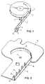
- Fig. 1
- eine perspektivische Ansicht einer mit einem Führungsband und einem Schieberelement versehenen kreisförmigen Scheibe und
- Fig. 2
- eine perspektivische Ansicht einer die Anordnung gemäß Fig. 1 aufnehmenden Platte.
- Die Steuervorrichtung enthält eine kreisförmige Scheibe 1, die mit einer Steuerachse 2 versehen ist, die in ein nicht dargestelltes Potentiometer eingreift und bei ihrer Drehung verstellt, wodurch die Leistung eines Antriebsmotors gesteuert wird. An der Scheibe 1 ist ein flexibles Steuerband 3 angeformt, an dessen freien Ende sich ein Schieberelement 4 befindet. Das Schieberelement 4 ist ein Formteil mit zwei parallel Stegen 5, die von einer Gabel eines ebenfalls nicht dargestellten Schieberknopfs übergriffen werden.
- Im Bereich des Ansatzes 6 des Führungsbandes 3 ist aus der kreisförmigen Scheibe 1 ein Abschnitt 7 weggeschnitten, wodurch ein Freiraum für ein Formwerkzeug zum Anformen des Führungsbandes 3 entsteht.
- In Fig. 2 ist eine Platte 8 dargestellt, die die Scheibe 1 aufnimmt, wobei die Steuerachse 2 der Scheibe 1 eine Bohrung 9 der Platte 8 durchgreift. Die Platte 8 wird ihrerseits auf eine nicht dargestellte gedruckte Schalterplatte aufgesetzt, an deren Unterseite sich das Potentiometer befindet, in das die Steuerachse 2 eingreift.
- Die Platte 8 enthält einen langgestreckten Steg 10 mit einem geradlinigen Abschnitt 11 und einem etwa halbkreisförmigen Abschnitt 12 sowie im Abstand zu dem Abschnitt 11 angeordnete kurze Stege 13. Diese Stege bilden seitliche Führungen für das Führungsband 3, das somit nicht seitlich ausweichen kann. Das Schieberelement 4 (Fig. 1) enthält an seiner Unterseite eine Nut 14, die geringfügig breiter als der Steg 11 ist, so daß das Schieberelement 4 verschiebbar auf den Steg 11 aufgesetzt werden kann. Am Ende des Stegs 11 befindet sich ein Anschlag 15 für das Schieberelement 4.
- Das Schieberelement 4 wird zur Verstellung des nicht dargestellten Potentiometers entlang des geradlinigen Führungsabschnitts 11 bewegt. Beim Vorschub in Richtung der Scheibe 1 dreht das Führungsband 3, das zwar flexibel, jedoch verhältnismäßig steif ausgebildet ist, die Scheibe 1 in Richtung des Pfeils A (Fig. 1), wobei sich das Führungsband 3 auf den Umfang der Scheibe 1 aufwickelt, da es weder zwischen den Stegen 11 und 13 des geradlinigen Führungsabschnitts noch zwischen dem Umfang der Scheibe 1 und dem kreisbogenförmigen Steg 12, der von dem Umfang der Scheibe 1 geringfügig beabstandet ist, seitlich ausweichen kann. Bei Bewegung des Schieberelements 4 in entgegengesetzter Richtung ändert sich entsprechend die Drehrichtung der Scheibe 1, wobei das Führungsband 3 von dem Umfang der Scheibe 1 abgewickelt wird.
Claims (12)
- Steuervorrichtung insbesondere für den Antriebsmotor eines Bodenstaubsaugers, mit einer kreisförmigen Scheibe (1) mit einer Steuerachse (2), die vorzugsweise in ein Potentiometer eingreift, das durch eine Drehbewegung der Steuerachse (2) verstellbar ist, und mit einer Einrichtung zum Drehen der Scheibe (1),
dadurch gekennzeichnet,
daß die Einrichtung zum Drehen der Scheibe (1) ein flexibles Führungsband (3) aufweist, das an dem Außenumfang der Scheibe (1) angeformt ist und dessen freies Ende mit einem Schieberelement (4) versehen ist, und daß das Führungsband (3) zwischen seitlichen Führungen (10, 11, 12, 13) angeordnet ist und eine solche Steifigkeit aufweist, daß es beim Vorschub des Schieberelementes (4) in Richtung der Scheibe (1) diese dreht und auf deren Umfang aufgewickelt wird. - Steuervorrichtung nach Anspruch 1,
dadurch gekennzeichnet, daß die Scheibe (1) auf einer Platte (8) angeordnet ist, die von der Steuerachse (2) der Scheibe durchgriffen ist und die seitlichen Führungen (10, 11, 12, 13) für das Führungsband (3) aufweist. - Steuervorrichtung nach Anspruch 1 oder 2,
dadurch gekennzeichnet, daß die seitlichen Führungen einen geradlinigen Abschnitt (11) aufweisen, der im wesentlichen tangential zu der Scheibe (1) verläuft. - Steuervorrichtung nach einem der Ansprüche 1 bis 3,
dadurch gekennzeichnet, daß die seitlichen Führungen ferner wenigstens teilweise den Außenumfang der Scheibe umgreifen. - Steuervorrichtung nach einem der Ansprüche 1 bis 4,
dadurch gekennzeichnet, daß die seitlichen Führungen durch Stege (10, 11, 12, 13) gebildet sind. - Steuervorrichtung nach Anspruch 5,
dadurch gekennzeichnet, daß das Schieberelement (4) auf einem Steg (10) verschiebbar angeordnet ist. - Steuervorrichtung nach Anspruch 1 oder 6,
dadurch gekennzeichnet, daß das Schieberelement als Bedienungsknopf ausgebildet ist. - Steuervorrichtung nach Anspruch 1 oder 6,
dadurch gekennzeichnet, daß das Schieberelement (4) von einer Gabel eines Schieberknopfes übergriffen wird. - Steuervorrichtung nach Anspruch 8,
dadurch gekennzeichnet, daß der Schieberknopf eine langgestreckte Form hat, so daß er einen zugehörigen Führungsschlitz in einem Staubsaugergehäuse in jeder Stellung überdeckt. - Steuervorrichtung nach Anspruch 1,
dadurch gekennzeichnet, daß im Bereich des Ansatzes (6) des Führungsbandes (3) ein Abschnitt (7) der Scheibe (1) weggeschnitten ist. - Steuervorrichtung nach Anspruch 10,
dadurch gekennzeichnet, daß der weggeschnittene Abschnitt (7) Teil eines Kreissegmentes ist, dessen eine Schnittlinie vom Ansatz (6) des Führungsbandes (3) in Richtung des Radius der Scheibe (1) verläuft. - Steuervorrichtung nach einem der Ansprüche 1 bis 11,
dadurch gekennzeichnet, daß die Scheibe (1), ihre Steuerachse (2) und das Führungsband (3) einstückig aus einem Kunststoff hergestellt sind.
Priority Applications (1)
| Application Number | Priority Date | Filing Date | Title |
|---|---|---|---|
| AT87113559T ATE72744T1 (de) | 1986-09-19 | 1987-09-16 | Steuervorrichtung. |
Applications Claiming Priority (2)
| Application Number | Priority Date | Filing Date | Title |
|---|---|---|---|
| DE19863631976 DE3631976A1 (de) | 1986-09-19 | 1986-09-19 | Steuervorrichtung |
| DE3631976 | 1986-09-19 |
Publications (3)
| Publication Number | Publication Date |
|---|---|
| EP0261580A2 EP0261580A2 (de) | 1988-03-30 |
| EP0261580A3 EP0261580A3 (en) | 1989-08-30 |
| EP0261580B1 true EP0261580B1 (de) | 1992-02-26 |
Family
ID=6309969
Family Applications (1)
| Application Number | Title | Priority Date | Filing Date |
|---|---|---|---|
| EP87113559A Expired - Lifetime EP0261580B1 (de) | 1986-09-19 | 1987-09-16 | Steuervorrichtung |
Country Status (3)
| Country | Link |
|---|---|
| EP (1) | EP0261580B1 (de) |
| AT (1) | ATE72744T1 (de) |
| DE (2) | DE3631976A1 (de) |
Families Citing this family (1)
| Publication number | Priority date | Publication date | Assignee | Title |
|---|---|---|---|---|
| DE102008012193A1 (de) * | 2008-03-03 | 2009-09-10 | Miele & Cie. Kg | Staubsauger mit einem Drehpotentiometer und einem Drehknopf |
Family Cites Families (3)
| Publication number | Priority date | Publication date | Assignee | Title |
|---|---|---|---|---|
| DE2031647A1 (de) * | 1970-06-26 | 1971-12-30 | Licentia Gmbh | Bodenstaubsauger mit einem mehrstufigen Schalter |
| US3800266A (en) * | 1973-03-05 | 1974-03-26 | Teac Corp | Variable resistor with linearly movable means for changing the resistance thereof |
| US4027541A (en) * | 1974-05-14 | 1977-06-07 | Matsushita Electric Industrial Co., Ltd. | Electronic component having a fine adjustment mechanism |
-
1986
- 1986-09-19 DE DE19863631976 patent/DE3631976A1/de not_active Withdrawn
-
1987
- 1987-09-16 AT AT87113559T patent/ATE72744T1/de not_active IP Right Cessation
- 1987-09-16 EP EP87113559A patent/EP0261580B1/de not_active Expired - Lifetime
- 1987-09-16 DE DE8787113559T patent/DE3776849D1/de not_active Expired - Fee Related
Also Published As
| Publication number | Publication date |
|---|---|
| EP0261580A3 (en) | 1989-08-30 |
| EP0261580A2 (de) | 1988-03-30 |
| DE3776849D1 (de) | 1992-04-02 |
| ATE72744T1 (de) | 1992-03-15 |
| DE3631976A1 (de) | 1988-03-31 |
Similar Documents
| Publication | Publication Date | Title |
|---|---|---|
| EP1037032B1 (de) | Mikrotom | |
| DE2444839B2 (de) | Granuliervorrichtung für Kunststoffe | |
| DE3513880A1 (de) | Geraet zum auspressen plastischer massen | |
| DE10131262A1 (de) | Anzeigeinstrument | |
| DE102017114226B4 (de) | Verriegelbarer schaltmechanismus zur verwendung in einer elektrischen vorrichtung | |
| DE2527634C3 (de) | Tragbare Schneidvorrichtung | |
| EP0261580B1 (de) | Steuervorrichtung | |
| EP3232545A1 (de) | Elektromotor | |
| EP1620611B1 (de) | Festellvorrichtung für eine verfahrbare wand | |
| WO2009103405A1 (de) | Feststellvorrichtung für eine verfahrbare wand | |
| DE2904159C2 (de) | Elektrisches Handgerät, wie Elektromesser, Handrührer o.dgl. | |
| DE3025797A1 (de) | Handwerkzeugmaschine mit einer einstellvorrichtung fuer das werkzeug | |
| DE19617227C1 (de) | Abschaltvorrichtung für den Antrieb eines zwischen Endstellungen verstellbaren Teils eines Fahrzeuges | |
| DE1908880A1 (de) | Durch einen Ausloeser betaetigte Schaltvorrichtung mit einer Stelleinrichtung fuer die Bewirkung mehrerer bestimmter Stellungen des Ausloesers | |
| DE19714834A1 (de) | Getriebeeinrichtung | |
| DE3326137A1 (de) | Rollbandmass | |
| EP0707541B1 (de) | Antriebsvorrichtung für ein verstellbares teil eines fahrzeuges | |
| DE69504767T2 (de) | Schneckenvorrichtung zur Positionierung in Fahrzeugscheinwerfer | |
| EP2745676A1 (de) | Werkzeugmaschine mit mindestens einer zum Ausführen einer Hubbewegung antreibbaren Arbeitsklinge | |
| WO2015018580A1 (de) | Plattenaufteilanlage | |
| DE3446656A1 (de) | Scheibenschneidmaschine, insbesondere fuer haushaltszwecke | |
| EP1440777B1 (de) | Kettensäge | |
| DE2919069C2 (de) | Schaltwerk zur Abstimmrückmeldung bei automatisch abgestimmten Senderbauelementen. | |
| DE1561789C3 (de) | Schreibgerät, insbesondere Kugelschreiber | |
| DE2510646C3 (de) | Vorrichtung zur Lagesteuerung eines bewegbaren Maschinenteils |
Legal Events
| Date | Code | Title | Description |
|---|---|---|---|
| PUAI | Public reference made under article 153(3) epc to a published international application that has entered the european phase |
Free format text: ORIGINAL CODE: 0009012 |
|
| AK | Designated contracting states |
Kind code of ref document: A2 Designated state(s): AT BE CH DE FR GB IT LI LU NL SE |
|
| PUAL | Search report despatched |
Free format text: ORIGINAL CODE: 0009013 |
|
| AK | Designated contracting states |
Kind code of ref document: A3 Designated state(s): AT BE CH DE FR GB IT LI LU NL SE |
|
| 17P | Request for examination filed |
Effective date: 19891006 |
|
| 17Q | First examination report despatched |
Effective date: 19910612 |
|
| GRAA | (expected) grant |
Free format text: ORIGINAL CODE: 0009210 |
|
| ITF | It: translation for a ep patent filed | ||
| AK | Designated contracting states |
Kind code of ref document: B1 Designated state(s): AT BE CH DE FR GB IT LI LU NL SE |
|
| REF | Corresponds to: |
Ref document number: 72744 Country of ref document: AT Date of ref document: 19920315 Kind code of ref document: T |
|
| GBT | Gb: translation of ep patent filed (gb section 77(6)(a)/1977) | ||
| REF | Corresponds to: |
Ref document number: 3776849 Country of ref document: DE Date of ref document: 19920402 |
|
| ET | Fr: translation filed | ||
| PLBE | No opposition filed within time limit |
Free format text: ORIGINAL CODE: 0009261 |
|
| STAA | Information on the status of an ep patent application or granted ep patent |
Free format text: STATUS: NO OPPOSITION FILED WITHIN TIME LIMIT |
|
| 26N | No opposition filed | ||
| PGFP | Annual fee paid to national office [announced via postgrant information from national office to epo] |
Ref country code: GB Payment date: 19930907 Year of fee payment: 7 |
|
| PGFP | Annual fee paid to national office [announced via postgrant information from national office to epo] |
Ref country code: DE Payment date: 19930908 Year of fee payment: 7 |
|
| PGFP | Annual fee paid to national office [announced via postgrant information from national office to epo] |
Ref country code: FR Payment date: 19930909 Year of fee payment: 7 Ref country code: AT Payment date: 19930909 Year of fee payment: 7 |
|
| PGFP | Annual fee paid to national office [announced via postgrant information from national office to epo] |
Ref country code: CH Payment date: 19930915 Year of fee payment: 7 |
|
| PGFP | Annual fee paid to national office [announced via postgrant information from national office to epo] |
Ref country code: SE Payment date: 19930917 Year of fee payment: 7 |
|
| PGFP | Annual fee paid to national office [announced via postgrant information from national office to epo] |
Ref country code: NL Payment date: 19930930 Year of fee payment: 7 Ref country code: LU Payment date: 19930930 Year of fee payment: 7 |
|
| PGFP | Annual fee paid to national office [announced via postgrant information from national office to epo] |
Ref country code: BE Payment date: 19931012 Year of fee payment: 7 |
|
| EPTA | Lu: last paid annual fee | ||
| PG25 | Lapsed in a contracting state [announced via postgrant information from national office to epo] |
Ref country code: LU Free format text: LAPSE BECAUSE OF NON-PAYMENT OF DUE FEES Effective date: 19940916 Ref country code: GB Effective date: 19940916 Ref country code: AT Effective date: 19940916 |
|
| PG25 | Lapsed in a contracting state [announced via postgrant information from national office to epo] |
Ref country code: SE Effective date: 19940917 |
|
| PG25 | Lapsed in a contracting state [announced via postgrant information from national office to epo] |
Ref country code: LI Effective date: 19940930 Ref country code: CH Effective date: 19940930 Ref country code: BE Effective date: 19940930 |
|
| EAL | Se: european patent in force in sweden |
Ref document number: 87113559.6 |
|
| BERE | Be: lapsed |
Owner name: PROGRESS ELEKTROGERATE G.M.B.H. Effective date: 19940930 |
|
| PG25 | Lapsed in a contracting state [announced via postgrant information from national office to epo] |
Ref country code: NL Effective date: 19950401 |
|
| GBPC | Gb: european patent ceased through non-payment of renewal fee |
Effective date: 19940916 |
|
| NLV4 | Nl: lapsed or anulled due to non-payment of the annual fee | ||
| PG25 | Lapsed in a contracting state [announced via postgrant information from national office to epo] |
Ref country code: FR Effective date: 19950531 |
|
| REG | Reference to a national code |
Ref country code: CH Ref legal event code: PL |
|
| PG25 | Lapsed in a contracting state [announced via postgrant information from national office to epo] |
Ref country code: DE Effective date: 19950601 |
|
| EUG | Se: european patent has lapsed |
Ref document number: 87113559.6 |
|
| REG | Reference to a national code |
Ref country code: FR Ref legal event code: ST |
|
| PG25 | Lapsed in a contracting state [announced via postgrant information from national office to epo] |
Ref country code: IT Free format text: LAPSE BECAUSE OF NON-PAYMENT OF DUE FEES;WARNING: LAPSES OF ITALIAN PATENTS WITH EFFECTIVE DATE BEFORE 2007 MAY HAVE OCCURRED AT ANY TIME BEFORE 2007. THE CORRECT EFFECTIVE DATE MAY BE DIFFERENT FROM THE ONE RECORDED. Effective date: 20050916 |