EP0260711B1 - Aortic valvuloplasty dilatation catheter instrument - Google Patents
Aortic valvuloplasty dilatation catheter instrument Download PDFInfo
- Publication number
- EP0260711B1 EP0260711B1 EP87113702A EP87113702A EP0260711B1 EP 0260711 B1 EP0260711 B1 EP 0260711B1 EP 87113702 A EP87113702 A EP 87113702A EP 87113702 A EP87113702 A EP 87113702A EP 0260711 B1 EP0260711 B1 EP 0260711B1
- Authority
- EP
- European Patent Office
- Prior art keywords
- catheter
- valve
- balloon
- distal
- dilatation balloon
- Prior art date
- Legal status (The legal status is an assumption and is not a legal conclusion. Google has not performed a legal analysis and makes no representation as to the accuracy of the status listed.)
- Expired - Lifetime
Links
- 238000013158 balloon valvuloplasty Methods 0.000 title claims description 8
- 210000001765 aortic valve Anatomy 0.000 claims description 47
- 238000000034 method Methods 0.000 claims description 44
- 230000002861 ventricular Effects 0.000 claims description 21
- 210000000709 aorta Anatomy 0.000 claims description 19
- 210000005240 left ventricle Anatomy 0.000 claims description 18
- 239000012530 fluid Substances 0.000 claims description 16
- 210000004351 coronary vessel Anatomy 0.000 claims description 14
- 238000005259 measurement Methods 0.000 claims description 13
- 230000017531 blood circulation Effects 0.000 claims description 11
- 238000002583 angiography Methods 0.000 claims description 9
- 210000002376 aorta thoracic Anatomy 0.000 claims description 9
- 238000002347 injection Methods 0.000 claims description 8
- 239000007924 injection Substances 0.000 claims description 8
- 230000007704 transition Effects 0.000 claims description 8
- 239000003351 stiffener Substances 0.000 claims description 7
- 230000004044 response Effects 0.000 claims description 6
- 238000010009 beating Methods 0.000 claims description 5
- 238000010438 heat treatment Methods 0.000 claims description 5
- 230000033001 locomotion Effects 0.000 claims description 5
- 201000006800 aortic valve disease 1 Diseases 0.000 claims description 4
- 238000005452 bending Methods 0.000 claims description 3
- 239000008280 blood Substances 0.000 claims description 3
- 210000004369 blood Anatomy 0.000 claims description 3
- 150000001875 compounds Chemical class 0.000 claims description 3
- 238000010276 construction Methods 0.000 claims description 3
- 229920001169 thermoplastic Polymers 0.000 claims description 3
- 239000004416 thermosoftening plastic Substances 0.000 claims description 3
- 230000006835 compression Effects 0.000 claims description 2
- 238000007906 compression Methods 0.000 claims description 2
- 238000009826 distribution Methods 0.000 claims description 2
- 230000002708 enhancing effect Effects 0.000 claims description 2
- 206010002906 aortic stenosis Diseases 0.000 description 11
- 230000000747 cardiac effect Effects 0.000 description 8
- 230000006872 improvement Effects 0.000 description 8
- 230000035488 systolic blood pressure Effects 0.000 description 8
- 230000003247 decreasing effect Effects 0.000 description 7
- 239000000463 material Substances 0.000 description 7
- 238000001356 surgical procedure Methods 0.000 description 6
- 230000006870 function Effects 0.000 description 5
- 230000001965 increasing effect Effects 0.000 description 5
- 206010002383 Angina Pectoris Diseases 0.000 description 4
- 206010002915 Aortic valve incompetence Diseases 0.000 description 4
- 208000004434 Calcinosis Diseases 0.000 description 4
- 208000031481 Pathologic Constriction Diseases 0.000 description 4
- 201000002064 aortic valve insufficiency Diseases 0.000 description 4
- 230000001435 haemodynamic effect Effects 0.000 description 4
- 238000012544 monitoring process Methods 0.000 description 4
- 230000002035 prolonged effect Effects 0.000 description 4
- 230000036262 stenosis Effects 0.000 description 4
- 208000037804 stenosis Diseases 0.000 description 4
- 206010042772 syncope Diseases 0.000 description 4
- 208000007177 Left Ventricular Hypertrophy Diseases 0.000 description 3
- 230000009471 action Effects 0.000 description 3
- 238000002399 angioplasty Methods 0.000 description 3
- 210000001367 artery Anatomy 0.000 description 3
- 210000000038 chest Anatomy 0.000 description 3
- 230000004087 circulation Effects 0.000 description 3
- 239000002872 contrast media Substances 0.000 description 3
- 230000003902 lesion Effects 0.000 description 3
- ZQPPMHVWECSIRJ-KTKRTIGZSA-N oleic acid Chemical compound CCCCCCCC\C=C/CCCCCCCC(O)=O ZQPPMHVWECSIRJ-KTKRTIGZSA-N 0.000 description 3
- 229940067292 osteum Drugs 0.000 description 3
- 239000000126 substance Substances 0.000 description 3
- 208000024891 symptom Diseases 0.000 description 3
- 208000006179 Aortic Coarctation Diseases 0.000 description 2
- 208000003017 Aortic Valve Stenosis Diseases 0.000 description 2
- 208000006029 Cardiomegaly Diseases 0.000 description 2
- 206010009807 Coarctation of the aorta Diseases 0.000 description 2
- 206010013971 Dyspnoea exertional Diseases 0.000 description 2
- 208000035211 Heart Murmurs Diseases 0.000 description 2
- 208000002193 Pain Diseases 0.000 description 2
- 206010067171 Regurgitation Diseases 0.000 description 2
- 208000031353 Systolic Murmurs Diseases 0.000 description 2
- 230000008901 benefit Effects 0.000 description 2
- 230000002308 calcification Effects 0.000 description 2
- 230000008859 change Effects 0.000 description 2
- 238000011161 development Methods 0.000 description 2
- 230000018109 developmental process Effects 0.000 description 2
- 230000035487 diastolic blood pressure Effects 0.000 description 2
- 230000003205 diastolic effect Effects 0.000 description 2
- 230000000916 dilatatory effect Effects 0.000 description 2
- 230000000694 effects Effects 0.000 description 2
- 210000001105 femoral artery Anatomy 0.000 description 2
- 230000001771 impaired effect Effects 0.000 description 2
- 238000001802 infusion Methods 0.000 description 2
- 208000014674 injury Diseases 0.000 description 2
- 238000003780 insertion Methods 0.000 description 2
- 230000037431 insertion Effects 0.000 description 2
- 239000002245 particle Substances 0.000 description 2
- 239000004033 plastic Substances 0.000 description 2
- 229920003023 plastic Polymers 0.000 description 2
- 230000008733 trauma Effects 0.000 description 2
- 238000003466 welding Methods 0.000 description 2
- 238000011265 2D-echocardiography Methods 0.000 description 1
- 206010000060 Abdominal distension Diseases 0.000 description 1
- 241000288963 Ariola Species 0.000 description 1
- OYPRJOBELJOOCE-UHFFFAOYSA-N Calcium Chemical compound [Ca] OYPRJOBELJOOCE-UHFFFAOYSA-N 0.000 description 1
- 206010008479 Chest Pain Diseases 0.000 description 1
- 206010010356 Congenital anomaly Diseases 0.000 description 1
- 208000019537 Congenital mitral stenosis Diseases 0.000 description 1
- 206010010548 Congenital mitral valve stenosis Diseases 0.000 description 1
- 201000000057 Coronary Stenosis Diseases 0.000 description 1
- 206010013012 Dilatation ventricular Diseases 0.000 description 1
- 208000005189 Embolism Diseases 0.000 description 1
- 208000010496 Heart Arrest Diseases 0.000 description 1
- HTTJABKRGRZYRN-UHFFFAOYSA-N Heparin Chemical compound OC1C(NC(=O)C)C(O)OC(COS(O)(=O)=O)C1OC1C(OS(O)(=O)=O)C(O)C(OC2C(C(OS(O)(=O)=O)C(OC3C(C(O)C(O)C(O3)C(O)=O)OS(O)(=O)=O)C(CO)O2)NS(O)(=O)=O)C(C(O)=O)O1 HTTJABKRGRZYRN-UHFFFAOYSA-N 0.000 description 1
- 206010049694 Left Ventricular Dysfunction Diseases 0.000 description 1
- 239000004698 Polyethylene Substances 0.000 description 1
- 238000012274 Preoperative evaluation Methods 0.000 description 1
- 206010037423 Pulmonary oedema Diseases 0.000 description 1
- FAPWRFPIFSIZLT-UHFFFAOYSA-M Sodium chloride Chemical compound [Na+].[Cl-] FAPWRFPIFSIZLT-UHFFFAOYSA-M 0.000 description 1
- 208000003443 Unconsciousness Diseases 0.000 description 1
- 208000009729 Ventricular Premature Complexes Diseases 0.000 description 1
- 206010047289 Ventricular extrasystoles Diseases 0.000 description 1
- JPKKQJKQTPNWTR-KQAYXBCTSA-N [(1r,5s)-8-methyl-8-azabicyclo[3.2.1]octan-3-yl] (2r)-3-hydroxy-2-phenylpropanoate;sulfuric acid;hydrate Chemical compound O.OS(O)(=O)=O.C1([C@H](CO)C(=O)OC2C[C@H]3CC[C@@H](C2)N3C)=CC=CC=C1.C1([C@H](CO)C(=O)OC2C[C@H]3CC[C@@H](C2)N3C)=CC=CC=C1 JPKKQJKQTPNWTR-KQAYXBCTSA-N 0.000 description 1
- 230000001154 acute effect Effects 0.000 description 1
- 230000003466 anti-cipated effect Effects 0.000 description 1
- 238000013459 approach Methods 0.000 description 1
- 230000004323 axial length Effects 0.000 description 1
- 230000000903 blocking effect Effects 0.000 description 1
- 210000004204 blood vessel Anatomy 0.000 description 1
- 230000037396 body weight Effects 0.000 description 1
- 210000004556 brain Anatomy 0.000 description 1
- 229910052791 calcium Inorganic materials 0.000 description 1
- 239000011575 calcium Substances 0.000 description 1
- 229960004362 clorazepate Drugs 0.000 description 1
- XDDJGVMJFWAHJX-UHFFFAOYSA-M clorazepic acid anion Chemical compound C12=CC(Cl)=CC=C2NC(=O)C(C(=O)[O-])N=C1C1=CC=CC=C1 XDDJGVMJFWAHJX-UHFFFAOYSA-M 0.000 description 1
- 206010010371 congenital aortic valve stenosis Diseases 0.000 description 1
- 229940039231 contrast media Drugs 0.000 description 1
- 238000001816 cooling Methods 0.000 description 1
- 238000013461 design Methods 0.000 description 1
- 238000003745 diagnosis Methods 0.000 description 1
- 201000010099 disease Diseases 0.000 description 1
- 208000037265 diseases, disorders, signs and symptoms Diseases 0.000 description 1
- 238000001125 extrusion Methods 0.000 description 1
- 230000010006 flight Effects 0.000 description 1
- ZZUFCTLCJUWOSV-UHFFFAOYSA-N furosemide Chemical compound C1=C(Cl)C(S(=O)(=O)N)=CC(C(O)=O)=C1NCC1=CC=CO1 ZZUFCTLCJUWOSV-UHFFFAOYSA-N 0.000 description 1
- 229960003883 furosemide Drugs 0.000 description 1
- 230000004217 heart function Effects 0.000 description 1
- 230000023597 hemostasis Effects 0.000 description 1
- 229960002897 heparin Drugs 0.000 description 1
- 229920000669 heparin Polymers 0.000 description 1
- 238000007373 indentation Methods 0.000 description 1
- 238000001990 intravenous administration Methods 0.000 description 1
- 238000011835 investigation Methods 0.000 description 1
- 230000001788 irregular Effects 0.000 description 1
- 230000002045 lasting effect Effects 0.000 description 1
- 230000036723 left ventricular dilatation Effects 0.000 description 1
- 239000007788 liquid Substances 0.000 description 1
- 238000004519 manufacturing process Methods 0.000 description 1
- 229920001179 medium density polyethylene Polymers 0.000 description 1
- 239000004701 medium-density polyethylene Substances 0.000 description 1
- 229910052751 metal Inorganic materials 0.000 description 1
- 239000002184 metal Substances 0.000 description 1
- 239000000203 mixture Substances 0.000 description 1
- 238000000465 moulding Methods 0.000 description 1
- 230000000422 nocturnal effect Effects 0.000 description 1
- 230000002093 peripheral effect Effects 0.000 description 1
- 230000037081 physical activity Effects 0.000 description 1
- -1 polyethylene Polymers 0.000 description 1
- 229920000573 polyethylene Polymers 0.000 description 1
- 238000009101 premedication Methods 0.000 description 1
- 230000008569 process Effects 0.000 description 1
- 230000000750 progressive effect Effects 0.000 description 1
- 210000001147 pulmonary artery Anatomy 0.000 description 1
- 208000002815 pulmonary hypertension Diseases 0.000 description 1
- 208000009138 pulmonary valve stenosis Diseases 0.000 description 1
- 208000030390 pulmonic stenosis Diseases 0.000 description 1
- 230000004043 responsiveness Effects 0.000 description 1
- 238000007788 roughening Methods 0.000 description 1
- 235000013580 sausages Nutrition 0.000 description 1
- 208000011818 severe chest pain Diseases 0.000 description 1
- 230000003746 surface roughness Effects 0.000 description 1
- 230000001225 therapeutic effect Effects 0.000 description 1
- 230000000472 traumatic effect Effects 0.000 description 1
- 230000002792 vascular Effects 0.000 description 1
- 238000012800 visualization Methods 0.000 description 1
Images


Classifications
-
- A—HUMAN NECESSITIES
- A61—MEDICAL OR VETERINARY SCIENCE; HYGIENE
- A61M—DEVICES FOR INTRODUCING MEDIA INTO, OR ONTO, THE BODY; DEVICES FOR TRANSDUCING BODY MEDIA OR FOR TAKING MEDIA FROM THE BODY; DEVICES FOR PRODUCING OR ENDING SLEEP OR STUPOR
- A61M25/00—Catheters; Hollow probes
- A61M25/0067—Catheters; Hollow probes characterised by the distal end, e.g. tips
- A61M25/0068—Static characteristics of the catheter tip, e.g. shape, atraumatic tip, curved tip or tip structure
- A61M25/007—Side holes, e.g. their profiles or arrangements; Provisions to keep side holes unblocked
-
- A—HUMAN NECESSITIES
- A61—MEDICAL OR VETERINARY SCIENCE; HYGIENE
- A61M—DEVICES FOR INTRODUCING MEDIA INTO, OR ONTO, THE BODY; DEVICES FOR TRANSDUCING BODY MEDIA OR FOR TAKING MEDIA FROM THE BODY; DEVICES FOR PRODUCING OR ENDING SLEEP OR STUPOR
- A61M25/00—Catheters; Hollow probes
- A61M25/0021—Catheters; Hollow probes characterised by the form of the tubing
- A61M25/0023—Catheters; Hollow probes characterised by the form of the tubing by the form of the lumen, e.g. cross-section, variable diameter
-
- A—HUMAN NECESSITIES
- A61—MEDICAL OR VETERINARY SCIENCE; HYGIENE
- A61M—DEVICES FOR INTRODUCING MEDIA INTO, OR ONTO, THE BODY; DEVICES FOR TRANSDUCING BODY MEDIA OR FOR TAKING MEDIA FROM THE BODY; DEVICES FOR PRODUCING OR ENDING SLEEP OR STUPOR
- A61M25/00—Catheters; Hollow probes
- A61M25/0021—Catheters; Hollow probes characterised by the form of the tubing
- A61M25/0041—Catheters; Hollow probes characterised by the form of the tubing pre-formed, e.g. specially adapted to fit with the anatomy of body channels
-
- A—HUMAN NECESSITIES
- A61—MEDICAL OR VETERINARY SCIENCE; HYGIENE
- A61M—DEVICES FOR INTRODUCING MEDIA INTO, OR ONTO, THE BODY; DEVICES FOR TRANSDUCING BODY MEDIA OR FOR TAKING MEDIA FROM THE BODY; DEVICES FOR PRODUCING OR ENDING SLEEP OR STUPOR
- A61M25/00—Catheters; Hollow probes
- A61M25/10—Balloon catheters
- A61M25/104—Balloon catheters used for angioplasty
-
- A—HUMAN NECESSITIES
- A61—MEDICAL OR VETERINARY SCIENCE; HYGIENE
- A61B—DIAGNOSIS; SURGERY; IDENTIFICATION
- A61B17/00—Surgical instruments, devices or methods, e.g. tourniquets
- A61B2017/00743—Type of operation; Specification of treatment sites
- A61B2017/00778—Operations on blood vessels
- A61B2017/00783—Valvuloplasty
-
- A—HUMAN NECESSITIES
- A61—MEDICAL OR VETERINARY SCIENCE; HYGIENE
- A61M—DEVICES FOR INTRODUCING MEDIA INTO, OR ONTO, THE BODY; DEVICES FOR TRANSDUCING BODY MEDIA OR FOR TAKING MEDIA FROM THE BODY; DEVICES FOR PRODUCING OR ENDING SLEEP OR STUPOR
- A61M25/00—Catheters; Hollow probes
- A61M25/0043—Catheters; Hollow probes characterised by structural features
- A61M2025/0063—Catheters; Hollow probes characterised by structural features having means, e.g. stylets, mandrils, rods or wires to reinforce or adjust temporarily the stiffness, column strength or pushability of catheters which are already inserted into the human body
-
- A—HUMAN NECESSITIES
- A61—MEDICAL OR VETERINARY SCIENCE; HYGIENE
- A61M—DEVICES FOR INTRODUCING MEDIA INTO, OR ONTO, THE BODY; DEVICES FOR TRANSDUCING BODY MEDIA OR FOR TAKING MEDIA FROM THE BODY; DEVICES FOR PRODUCING OR ENDING SLEEP OR STUPOR
- A61M25/00—Catheters; Hollow probes
- A61M25/01—Introducing, guiding, advancing, emplacing or holding catheters
- A61M25/0105—Steering means as part of the catheter or advancing means; Markers for positioning
- A61M25/0108—Steering means as part of the catheter or advancing means; Markers for positioning using radio-opaque or ultrasound markers
Definitions
- This invention relates to an aortic valvuloplasty dilatation catheter instrument, useful for adult patients having aortic stenosis, especially acquired calcific stenosis, a disease which is prevalent in elderly people.
- Percutaneous transluminal balloon catheter angioplasty is a recognized treatment for peripheral and coronary artery stenoses. This technique has also been used successfully in certain forms of coarctation of the aorta, pulmonary stenosis, congenital aortic valve stenosis, and mitral stenosis, but not previously in adults with acquired aortic valve stenosis. It might be thought impossible to dilate such long-standing and usually calcified lesions because of the anticipated critical effects of the expected disruption of the aortic blood flow in the weakened patient and the apparently serious risk of dislodging particles of the calcific plaque to produce life-threatening emboli in the blood stream.
- GB-A-2 123 300 describes a device for urodynamic testing on the lower urinary tract, consisting of an elongated catheter defining three or four lumens, three of the lumens terminating in an inflatable balloon disposed between second and third openings.
- PTAV percutaneous transluminal balloon catheter aortical valvuloplasty
- a dilatation procedure for treating patients having calcific aortic stenosis, in which there are calcific deposits on the leaflets of the aortic valve that impair their opening movement during systole comprising the steps of: introducing a dilatation balloon into the stenosed aortic valve via the aorta while the blood circulation of the patient is maintained by the heart via the aortic valve, inflating the balloon to grossly deflect the calcific leaflets of the valve in a manner avoiding blocking the outer portions of the commissures of the valve, the inflating step enabling substantial blood flow through the outer portions of the commissures during systole despite the presence in the valve of the inflated balloon, and prolonging the inflation of the balloon over an interval spanning a large multiplicity of heart beats, e.g.
- the leaflets may be repeatedly, oppositely stressed by exposure to alternating systolic and diastolic pressure conditions to improve their action.
- the inflation of the balloon is so performed that, during the inflation, the calculated effective flow cross-section in the unblocked outer portions of the commissures during systole is of the order of or greater than the calculated flow cross-section during systole of the stenosed valve prior to the dilatation;
- the balloon is selected to have an average inflated diameter in the range between about 14 and 24 mm;
- the interval of prolonged inflation is preferably of the order of one minute or more and preferably no greater than about 5 minutes;
- the aortic pressure is monitored during the inflation and the inflation is discontinued upon the occurrence of substantial decrease in aortic pressure during systole; prior to inflation of the balloon in the valve, the pressure gradient is measured across the aortic valve in the absence of the balloon within the valve, to establish a pre-dilatation base-line value for the flow-restriction imposed by the stenosed valve, and during the
- a method of aortic valvuloplasty comprises the following steps:
- the method includes, after withdrawing the balloon as provided in step G, thrusting the balloon forward to cause the stiff segment to guide the balloon back into the valve, and thereafter repeating steps E, F and G before removing the catheter from the patient; the method further includes, during the inflation of the balloon, continually monitoring the aortic pressure and deflating the balloon and withdrawing it from the valve upon the occurrence of significant drop in aortic pressure, preferably the method further comprises, where desirable, repeating steps E through G until an acceptable pressure gradient is achieved, and preferably the method further includes continually monitoring aortic pressure and, under the conditions that the aortic pressure has not significantly dropped and pressure differential across the valve has remained above about 30 mm Hg, repeating steps E, F and G; the balloon is of stepped construction of two different diameters, with the smaller diameter portion positioned distally of the larger diameter portion, and the method comprises dilating the valve with the smaller diameter balloon portion and then dilating the valve with the larger diameter portion; the method further comprises the step of taking a vent
- the invention also features aortic valvuloplasty dilatation catheters per se, constructed as described above.
- the first portion of the catheter incorporates a single lumen adapted to slide over a guidewire and to serve for measurement of ventricular pressure and the second portion of the catheter incorporates that lumen and at least two additional lumens, one of which is adapted for measurement of aortic pressure and another of which is adapted for inflation of the balloon;
- the two portions of the catheter are integral, the first portion of the catheter being the product of heating and radial collapsing of a multiple lumen catheter of thermoplastic while only the single lumen is supported by a mandrel residing within the lumen;
- a stiffener rod is permanently embedded within the catheter, the rod extending distally to the point lying distal of the balloon, preferably the distal tip of the rod being fixed with respect to the catheter, proximal portions of the rod being free to slide in the lumen relative to the catheter in response for instance to bending of the catheter and/or preferably an extended sleeve integral with the balloon extends distally of the
- the balloon preferably has a number of other preferred features: it is of stepped construction having at least two different diameters and has tapered transition portions, preferably, in a two diameter balloon the smaller diameter portion of the balloon comprising the distal portion of the balloon being between about 2 and 2.5 cm in length and having a diameter between about 14 and 18 mm and the larger diameter portion of the balloon comprising the proximal portion of the balloon being between about 3 and 3.5 cm in length and having a diameter between about 18 and 24 mm, the tapered transition portions at the ends of the balloon having a length between about 1/2 and 1 cm and the transition between the two balloon diameters being of the order of 1/2 cm in length; a bend in the catheter is provided of between about 20° and 30°, located immediately proximal of the balloon and adapted to ease the passage of the catheter through the aortic arch; the distal portion of the catheter has a compound curvature, the distal-most portion having a smaller radius of curvature than
- an aortic catheter comprises a multilumen catheter having at least two pressure-measuring lumens, one pressure-measuring lumen terminating in a distal sensing port means disposed on a distal portion of the catheter, the sensing port means adapted for measuring pressure in the left ventricle of the heart, a second pressure-measuring lumen terminating in a proximal sensing port means disposed proximally along said catheter, the second sensing port means adapted for measuring aortic pressure, the distal sensing port means being spaced distally a distance sufficient that, while the catheter resides within an aortic valve, the catheter tip extends through the valve, for positioning the distal sensing port means entirely within the left ventricle of the heart, whereby when the catheter is positioned with the distal sensing port means lying entirely within the left ventricle, by use of the distal and proximal sensing port means, the pressure gradient across the valve can be measured while the heart is beating.
- Left ventricular catheterization showed left ventricular pressures of 245/28 mm Hg and aortic pressures of 155/70 mm Hg (systolic pressure gradient 90 mm Hg).
- Aortic valve cusps were moderately calcified.
- Selective left ventricular angiography showed a normal diastolic volume (73 ml/m2), with normal left ventricular function (ejection fraction 775) and clearly thickened walls. Post-stenotic dilatation of the ascending aorta and slight aortic regurgitation were seen on aortic angiography.
- Selective coronary arteriography did not show any significant coronary lesions. The patient gave informed consent for PTAV as an alternative to surgical valve replacement and this was done three weeks later.
- Cardiac catheterization demonstrated ventricular pressures of 230/22 mm Hg and aortic pressures of 100/50 mm Hg (systolic pressure gradient 130 mm Hg).
- the aortic valve was massively calcified.
- Right heart pressures and cardiac index were normal.
- Left ventricular angiography showed a normal end-diastolic volume (94 ml/m2) with slightly reduced ejection fraction (54%) and thickened walls.
- the ascending aorta was moderately dilated, and aortic regurgitation was insignificant. Selective coronary arteriogram was normal.
- ECG showed severe left ventricular hypertrophy and the chest radiograph mild cardiomegaly and signs of mild pulmonary hypertension.
- 2D echocardiogram showed severe aortic stenosis with considerable valve calcification and severe left ventricular dilatation with impaired ventricular function.
- left ventriculiar pressure was 140/28 mm Hg (systolic pressure gradient 60 mm Hg) and the aortic valves were massively calcified.
- Left ventricular angiography confirmed left ventricular dysfunction, with an increased diastolic volume (190 ml/m2) and greatly decreased ejection fraction (20%).
- Selective coronary arteriography showed major multiple vessel lesions with proximal left-anterior-descending occlusion.
- a 5F catheter was inserted into the descending thoracic aorta.
- a Swan-Ganz thermodilution catheter was inserted into the pulmonary artery in patients 2 and 3 for measurement of cardiac output.
- Left ventricular catheterization was carried out via the brachial approach which made it easier to cross the stenosed aortic orifice (and was also necessitated by the short length (60 cm) of the dilatation catheters available in our laboratory).
- a 7F Sones catheter was inserted into the aorta and then in the left ventricle.
- ECG and aortic pressure were continuously recorded during the procedure. Ventricular and aortic pressures were simultaneously measured after each series of inflations. At the end of the procedure, an aortic root angiogram was done to assess valve opening and residual aortic regurgitation.
- the aortic pressure never decreased below 60mm Hg.
- the obstruction caused by the inflated balloon was therefore incomplete; this was confirmed by manual injection of a few ml of contrast medium into the ventricular cavity during one inflation (via the angioplasty catheter with guidewire removed). A few premature ventricular contractions occurred infrequently during the inflations.
- transvalvular gradient was 90 mm Hg at the start of the procedure and remained unchanged after the first two series of inflations with the 8 and 10 mm balloons. After a series of these inflations with the 12 mm balloon, it decreased to 40 mm Hg.
- the mitral gradient was found to be 80 mm Hg (rather than the 130 mm Hg measured during the initial catheterization) and decreased to 70, 60 and finally 30 mm Hg after each series of inflations.
- improvement of systolic gradient was very similar - from 60 mm Hg to 50, 40, and finally 30 mm Hg.
- valve surface calculated according to Gorlin's formula increased from 0.46 cm2 to 0.96 cm2 and from 0.50 cm2 to 0.75 cm2, respectively.
- Aortic root angiography showed no worsening of the aortic regurgitation. Valve motion, which was considerably impaired before the procedure, was greatly improved, especially in the second patient.
- PTAV can offer a simple therapeutic alternative to patients, mostly elderly, in whom surgery would be risky or impossible.
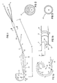
- the aortic valvuloplasty dilatation catheter instrument 10 comprises a 9 French catheter of about 100 cm length formed over a major portion of its length as a multilumen extrusion of medium density polyethylene material.
- the catheter has three lumens over its proximal length, L p .
- the main catheter body 8 terminates (see Fig. 1b) and a single lumen catheter extension 13 of relatively stiff material is joined, e.g., by lap welding, to it.
- a second single lumen catheter extension 15 of relatively softer material is joined, e.g., by lap welding, to the distal end of catheter extension 13.
- Second lumen 12 is for balloon inflation-deflation and terminates at port 26 in the end surface 28 of main catheter 8 within dilatation balloon 22.
- the third lumen 16 is a proximal pressure measuring lumen that opens at a proximal port 32, about 4 mm long and 0.8 mm wide, situated approximately 10 cm proximal of the balloon, for measurement of pressure and infusion of fluids. (The end of lumen 16 is sealed by plug 30 at surface 28).
- Lumens 12, 16 have diameter of about 0.8 mm each.
- the catheter has an extended curved distal portion of length, L d , beyond the balloon of about 5 cm length, having six side holes 21, defined on the inside of the curve, each having diameter between about 0.64 to 0.76 mm (0.025 to 0.030 inch).
- the closest hole is placed 3 cms from the balloon and the others are spaced distally therealong at regular intervals.
- This distal portion of the catheter is of compound curvature, as shown, with the distal-most part L t having the smallest radius, the total arc of curvature being about 300°.
- the tip is thus shaped so it will rest directed back toward the inside of the curve to avoid contact with the interior wall of the ventricle, and to present a nontraumatic surface to the inner lining of the heart.
- the side holes in the distal portion are designed for measurement of pressure inside the ventricle and also for injection of radiopaque contrast fluid for ventricular graphs at the end of the procedure.
- the multiple side holes protect against the possibility that one or more holes may become occluded by rubbing up against the wall of the heart and also enable the relatively viscous contrast fluid, when injected, to be dispersed evenly and in desirably large amounts.
- the distance from the balloon of the first or most proximal side hole 21 is established to make it possible to deflate the balloon when within the valve, withdraw the balloon into the ascending aorta, leaving the most proximal hole 21 still within the ventricle beyond the valve, so that the pressures measured through the distal lumen are the ventricular pressures. These pressures are compared to the pressures measured through the proximal port 32 and lumen 12, these two measurements providing an accurate measurement of pressure gradient across the aortic valve.
- bands 36, 38, 40 of radiopaque material Disposed about the catheter are bands 36, 38, 40 of radiopaque material which give the cardiologist an accurate radiographic image of the location of the balloon in relation to the aortic valve.
- the distal portion of the catheter has an outer diameter of about 7 French and is of relatively softer material.
- the distal tip is made more flexible than the main body of the catheter, and is also made less traumatic to the wall of the ventricle and more able to easily follow the guidewire.
- the main body of the catheter is larger in outer diameter, e.g., about 3.05 mm, compared to the diameter of the distal portion, e.g., about 2.54 mm, and the catheter extension 13 within the balloon is of relatively stiffer material, giving the main body sufficient axial stiffness to permit the physician to push the balloon repeatedly through the aortic valve and providing a substantial resistance to torque so that the catheter may be twisted to facilitate insertion or to position the tip in a desired place, such as in the coronary artery during withdrawal for injection of contrast media for a coronary radiograph.
- the balloon itself has a thickness of 0.089 mm (0.0035 inch) and is formed of polyethylene that is biaxially oriented and treated to make it strong and noncompliant, with strength sufficient to withstand inflation pressures, of the order of 4 to 6 atmospheres, or higher (burst pressure of the order of eight atmospheres).
- the balloon is approximately 10 cm in length, and tapers gradually from the 9 French catheter shaft at the proximal end and the 7 French tip on the distal end to the full balloon diameter. The full diameter is different at the two ends of the balloon. On the distal end 42 there is a smaller balloon section, of 16 mm diameter and at the proximal end 44 there is a larger diameter balloon section of 20 mm diameter.
- the axial length of the distal portion 42 is between about 2 and 2 1/2 cm and the length of the proximal portion 44 is between about 3 and 3 1/2 cm.
- the tapered transition portions at each end of the balloon have lengths of one half up to one centimeter, and the transition between the two balloon diameters has a length of about one half centimeter.
- the balloon terminates distally in a sleeve 43 which makes the corresponding portion of the catheter relatively more stiff than the tip portion to aid in the passage of the balloon when it crosses or re-crosses the valve.
- the tip portion itself is very flexible and is able to conform to the contours of the ventricle to which it is exposed.
- the distal sleeve 43 is between 1 and 2 cms in length and has a diameter of about 0.125 inch.
- the proximal sleeve 45 is curved at an angle between 20 and 30° to provide to the catheter a geometry which eases passage of the device through the aortic arch.
- the distal sleeve 43 and proximal sleeve 45 are integral continuations of the balloon, and serve to attach the balloon to the catheter itself.
- the balloon is attached to the catheter by heating the material of the sleeves and the underlying catheter to melt them together.
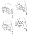
- a guidewire 50 is introduced into a puncture in the femoral artery of the patient and advanced through the aorta.
- the guidewire is advanced and allowed to coil inside the left ventricle (Figs. 4, 4a, 5).
- the aortic valve dilatation catheter 10 of the invention is advanced along the guidewire, the leading portion of the catheter, conforming to the shape of the guidewire.
- the tip 20 is pushed through the aortic valve over the guidewire (Fig. 6).
- This is followed by the relatively stiff section of the sleeve 43 which helps to dilate the valve (Fig. 7).
- the catheter may be preceded in these steps by a diagnostic catheter or the dilatation catheter 10 itself may be employed for diagnostic purposes.
- the guidewire is withdrawn and the sleeve is positioned within the valve (Fig. 8), as determined by the physician observing the radiopaque rings 38, 40 at either side of valve AV.
- the physician When ready to commence dilatation, the physician, taking advantage of the relatively stiff sleeve lodged in the valve, advances the deflated balloon between the valve leaflets, V L (Figs. 9, 9a). During this motion, the tip portion L d assumes its preset curve corresponding to the curved interior wall of the ventricle, the tip portion presenting a nontraumatic surface to the ventricle, the reduced diameter and added flexibility of the distal portion and its pre-set curve enabling this to occur with ease and without trauma to the ventricle wall.
- the balloon While aortic pressure is being monitored, the balloon is inflated with liquid and the valve is dilated with first the small diameter section of the balloon 42. After an interval, the balloon is deflated and withdrawn into a position where the tip of the catheter, including all the holes 21, remains inside the ventricle, with the balloon out of the valve, in the aorta, and the stiff sleeve is lying within the valve, Fig. 10.
- Pressures are again recorded through the distal and proximal lumens and the pressure gradient across the valve is determined.
- the balloon is reinserted into the valve, facilitated by the stiff sleeve, without need to reinsert the guidewire (Fig. 11), this time the larger section of the balloon 44 being placed in the valve, and the balloon is again inflated.
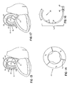
- Inflation of the balloon may be maintained from a few seconds (e.g., in the case of rapid decrease of aortic pressure) to many minutes, depending upon the condition of the patient. It is found, surprisingly, in a large majority of elderly and gravely ill patients, that despite the stenosed condition of the aortic valve, and the presence of the inflated balloon in the valve, the aortic pressure does not rapidly deteriorate. This is attributed to a special condition achieved at the commissures, C, the region of contact between the valve leaflets. It is found that when the inflated balloon is in place, the outer portions C o of the commissures C, open to provide a calculated flow cross sectional area commensurate with or even in some instances greater than the original stenosed calculated flow cross section of the valve.
- a cylindrical shape of balloon is helpful in enabling the balloon to be left inflated for an extended period. This is attributed to the fact that a cylindrical balloon shape does not take up the space all the way to the root of the leaflets to block flow while it assures considerable distortion of the leaflets in their root region. This facilitates flow through the outer commissure regions C o held open by the balloon.
- the calcium deposits on the leaflets are fractured or disrupted without dislodgement, which enables them to open wider and close more easily in response to the action of the heart, to provide better flow.
- the balloon is again deflated.
- the balloon is again removed from the valve and, with the sleeve within the valve, the pressure gradient again measured between the aorta and the ventricle, Fig. 12. If this pressure gradient has decreased sufficiently, e.g., to 30 mm Hg, the procedure is regarded as successfully completed.
- the physician may perform another ventriculogram by injecting contrast fluid through the distal lumen of the catheter to exit the side holes 21 in the distal portion of the catheter, to observe the wall motion of the ventricle and the level of cardiac function.
- an aortogram is performed to confirm that the valve is closing so there is no regurgitation into the ventricle during diastole.
- the catheter is then removed from the femoral artery, and the artery is compressed until hemostasis occurs and the patient is returned to his room.
- the balloon may have a maximum inflated diameter of up to 24 mm, selected on the basis of the patient's physical characteristics to be less than the diameter of the aortic root to avoid stretching of the root, and obstruction of flow and to avoid over-distention of the leaflets that could result in regurgitation of flow or evulsion of leaflets.
- the balloon may have another shape, e.g., it may be a sausage shape of uniform diameter, or be specially shaped to increase blood flow through the commissures during inflation.
- a multilobe balloon e.g., formed by molding, with 3 or 4 lobes, may be employed to improve blood flow during dilatation (Fig. 14).
- the catheter may include a fourth lumen containing a rod, e.g., of metal or plastic, to provide additional stiffness and torqueability of the catheter over its length to the distal end of the balloon, while not affecting the soft tip.
- the stiffener may be fixed in the lumen, see below, or may be movable to vary the stiffened length of the catheter, and the stiffener may be tapered to vary the degree of stiffness provided.
- a four lumen catheter is provided, lumens 12, 14 and 16 serving the functions of the lumen of like numbers in Fig. 1, while lumen 60 is blind, i.e., it has no outlet at its distal end.
- a stiffener rod 60 is permanently inserted in this blind lumen and which is anchored at its distal end relative to the catheter and which is otherwise free to slide relative to the catheter e.g. during bending of the catheter or when subjected to a large change in temperature. This rod provides added stiffness in the region extending distally to the sleeve region beyond the balloon for facilitating crossing and re-crossing of the stenosed aortic valve.
- a preferred means of fixing the distal end of the rod within the catheter is by the provision of surface roughening at 62 at the distal end, and heating the substance of the catheter, for instance during the affixation of the balloon to cause the plastic to flow into the interstices of the surface roughness, thus to provide a mechanical grip upon the roughened end of the rod.
- An alternate manufacturing technique involves placing a mandrel in the distal portion of the distal lumen 14 while leaving the other lumens unsupported from within, heating the thermoplastic substance of this portion of the catheter and radially compressing the substance of the catheter to reform it about the mandrel, and cooling. This process closes the smaller lumens 12, 16 and reduces the diameter of the distal lumen 14 to about 1.12 mm, with the distal opening having a diameter of about 1 mm.
- the distal tip portion may have a shape of somewhat less curvature, e.g., about 200°, to enable it to be positioned in the left main coronary artery osteum (Fig. 17).
- the physician can inject contrast fluid through the distal lumen into the left coronary artery to observe the coronary artery circulation. Due to the relative sizes of the distal and side holes, a sufficient volume of the contrast fluid flows into the coronary artery to allow visualization of the artery.
- a catheter device of the invention formed of a catheter body 100 without an inflatable balloon (Fig. 18), may be employed for diagnosis in simultaneously measuring the pressure on both sides of the valve for determination of the gradient.
Landscapes
- Health & Medical Sciences (AREA)
- Life Sciences & Earth Sciences (AREA)
- Heart & Thoracic Surgery (AREA)
- Anesthesiology (AREA)
- Biophysics (AREA)
- Pulmonology (AREA)
- Engineering & Computer Science (AREA)
- Biomedical Technology (AREA)
- Hematology (AREA)
- Animal Behavior & Ethology (AREA)
- General Health & Medical Sciences (AREA)
- Public Health (AREA)
- Veterinary Medicine (AREA)
- Child & Adolescent Psychology (AREA)
- Vascular Medicine (AREA)
- Media Introduction/Drainage Providing Device (AREA)
Description
- This invention relates to an aortic valvuloplasty dilatation catheter instrument, useful for adult patients having aortic stenosis, especially acquired calcific stenosis, a disease which is prevalent in elderly people.
- Stenosis of the aortic valve has long been known to cause serious diminishment of blood flow from the heart. The critical position of the aortic valve, preceding the arteries that nourish the heart and brain as well as all other parts of the body, makes this a very serious ailment.
- For those patients sufficiently well to endure the surgery, it has become common to replace the aortic valve with a prosthetic device while the patient is maintained by an extra-corporeal circulation system that by-passes the heart and valve. There is, however, risk with this major surgical procedure and there remains a large population who are too weak or otherwise do not wish to undergo such surgery.
- Percutaneous transluminal balloon catheter angioplasty is a recognized treatment for peripheral and coronary artery stenoses. This technique has also been used successfully in certain forms of coarctation of the aorta, pulmonary stenosis, congenital aortic valve stenosis, and mitral stenosis, but not previously in adults with acquired aortic valve stenosis. It might be thought impossible to dilate such long-standing and usually calcified lesions because of the anticipated critical effects of the expected disruption of the aortic blood flow in the weakened patient and the apparently serious risk of dislodging particles of the calcific plaque to produce life-threatening emboli in the blood stream.
- References to work prior to commencement of our development are:
Cooper, R.S.; Ritter, S.B.; Golinko, R.J.; Balloon dilatation angioplasty: Nonsurgical management of coarctation of the aorta; Circulation, 1984; 70:903-07.
Kan, J.S.; White, R.I.; Mitchell, S.E.; Anderson, J.H.; Gardner, T.J.; Percutaneous transluminal balloon valvuolplasty for pulmonary valve stenosis; Circulation, 1984; 69:554-60.
Lababidi, Z.; Wu, J.R.; Percutaneous balloon pulmonary valvuloplasty; Am J. Cardiol, 1983; 52:560-62.
Pepine, C.J.; Gessner, I.H.; Feldman, R.L.; Percutaneous balloon valvuloplasty for pulmonic valve stenosis in the adult; Am. J. Cardiol, 1982; 50:1442-45.
Rey, C.; Marache, P.; Matina, D.; Mouly, A.; Valvuloplastie transluminale percutanee des stenoses pulmonaires; A propos de 24 cas, Arch Mal Cocur, 1985; 78:703-10.
Rocchini, A.P.; Kveselis, D.A.; Crowley, D.; Dick Mac, D.; Rosenthal, A; Percutaneous balloon valvuloplasty for treatment of congenital pulmonary valvular stenosis in children; J. Am. Coll Cardiol, 1984; 3:1005-12.
Lababidi, Z.; Wu, J.R.; Walls, J.T.; Percutaneous balloon aortic valvuloplasty: results in 23 patients; Am J. Cardiol, 1984; 53:194-97.
Lock, J.E.; Castaneda-Zuniga, W.R.; Fuhrman, B.P.; Bass, J.L.; Balloon dilation angioplasty of hypoplastic and stenotic pulmonary arteries; Circulation, 1983; 67, 5:962-7.
Walls, J.T.; Lababidi, Z.; Curtis, J.J.; Silver, D.; Assessment of percutaneous balloon pulmonary and aortic valvuloplasty; J. Thorac. Cardiovasc. Surg., 1984; 88:352-56.
Inoue, K.; Owaki, T.; Nakamura, T.; Kitamure, F.; Miyamoto, N.; Clinical application of transvenous mitral commissurotomy by a new balloon catheter; J. Thorac. Cardiovasc. Surg., 1984; 87:394-402.
Cohen, M.V.; Gorlin, R.; Modified orifice equation for the calculation of mitral valve area; Am. Heart J., 1972; 84:839.
Brockmeier, L.B.; Adoph, R.J.; Gustin, B.W.; Holmese, J.C.; Sacks, J.G.; Calcium emboli to the retinal artery in calcific aortic stenosis; Am. Heart J. , 1981; 101:32-37. - GB-A-2 123 300 describes a device for urodynamic testing on the lower urinary tract, consisting of an elongated catheter defining three or four lumens, three of the lumens terminating in an inflatable balloon disposed between second and third openings.
- In the beginning of our work (Cribier and Letac), percutaneous transluminal balloon catheter aortical valvuloplasty (PTAV) was carried out in three elderly patients with acquired severe calcific aortic valve stenosis. In all 3 cases, severity of progression made valve replacement appear both mandatory and urgent. We elected to attempt valvuloplasty, however, because advanced age and poor physical condition made the operative risk very high in 2 patients, while the third refused to contemplate surgery. Transvalvular systolic pressure gradient was considerably decreased at the end of each procedure, during which there were no complications. Increased valve opening was confirmed by a decrease in pressure gradient and an increase in valve area, calculated by Gorlin's formula using measurement of cardiac output. Subsequent clinical course showed a pronounced functional improvement. (For simplicity, in the following text, measured pressure gradient will be used to denote the results.)
- In the course of this work, and confirmed by many follow-up cases, it has been discovered that placement of an appropriately sized inflated balloon in an aortic valve that is seriously stenosed as a result of calcific plaque build-up, does not, in the majority of cases, significantly worsen blood flow through the stenosed valve during a prolonged treatment (greater than thirty seconds, up to four minutes); that dilatation and in particular prolonged dilatation provides a very desirable increase in pressure-responsiveness of the valve leaflets to produce a larger arterial flow; that the calcific plaque, though effectively disturbed by the dilatation does not result in significant entry of free particles in the vascular system, so that life-threatening calcific emboli are not generally formed; and we have confirmed, by correlation with measured cardiac output, that measurement of pressure gradient across the valve, even with a catheter present in the valve, is useful as one indication of the improvement achieved by the procedure.
- As a further, very important aspect of the invention, we (Cribier and Letac) have conceived a multipurpose aortic valve dilatation catheter, and procedure using it, that significantly reduces the number of procedural steps, reduces the time required for the procedure, and enhances patient safety. The final design (to which Ariola contributed) has been demonstrated to facilitate re-entry into the valve for repeated dilatation of the aortic valve without need of a guidewire, to enable monitoring of the results at each step, and to enable ventriculograms, aortograms, and angiograms of the left coronary artery. Use of the device significantly reduces trauma to the blood vessels, and provides significant improvement in patient comfort.
- Certain features of the aortic valvuplasty dilatation cathether instrument according to the invention are summarized in more detail as follows:
- A dilatation procedure for treating patients having calcific aortic stenosis, in which there are calcific deposits on the leaflets of the aortic valve that impair their opening movement during systole, comprising the steps of: introducing a dilatation balloon into the stenosed aortic valve via the aorta while the blood circulation of the patient is maintained by the heart via the aortic valve, inflating the balloon to grossly deflect the calcific leaflets of the valve in a manner avoiding blocking the outer portions of the commissures of the valve, the inflating step enabling substantial blood flow through the outer portions of the commissures during systole despite the presence in the valve of the inflated balloon, and prolonging the inflation of the balloon over an interval spanning a large multiplicity of heart beats, e.g. thirty seconds or longer, whereby the calcific deposits on the leaflets are disturbed to increase the pliability of the leaflets and the degree of their opening in response to systolic pressure, the calcific deposits, though thus disturbed by the dilatation, remaining as part of the leaflets so that life-threatening emboli do not form. In this manner, while grossly deflected by the balloon, the leaflets may be repeatedly, oppositely stressed by exposure to alternating systolic and diastolic pressure conditions to improve their action.
- In carrying out the above procedure there are a number of preferred further features: the inflation of the balloon is so performed that, during the inflation, the calculated effective flow cross-section in the unblocked outer portions of the commissures during systole is of the order of or greater than the calculated flow cross-section during systole of the stenosed valve prior to the dilatation; where the treatment is of a normally sized adult, the balloon is selected to have an average inflated diameter in the range between about 14 and 24 mm; the interval of prolonged inflation is preferably of the order of one minute or more and preferably no greater than about 5 minutes; the aortic pressure is monitored during the inflation and the inflation is discontinued upon the occurrence of substantial decrease in aortic pressure during systole; prior to inflation of the balloon in the valve, the pressure gradient is measured across the aortic valve in the absence of the balloon within the valve, to establish a pre-dilatation base-line value for the flow-restriction imposed by the stenosed valve, and during the procedure, following inflation of the balloon within the valve, the balloon is withdrawn from the valve, the pressure gradient is re-measured, and the procedure is terminated when the gradient has substantially decreased, e.g., to about 30 mm Hg or less; preferably these pressure gradients being measured while a distal portion of the balloon catheter is within the valve; a multilumen dilatation catheter is provided having at least two pressure-measuring lumens in addition to lumen means that inflates the balloon, one of the pressure-measuring lumens terminating in distal sensing port means disposed on the portion of the catheter distal of the balloon, the sensing port means adapted for measuring pressure in the left ventricle of the heart, and a second of the pressure-measuring lumens terminating in a proximal sensing port means disposed along the catheter proximal of the balloon, the second sensing port means adapted for measuring aortic pressure, the distal sensing port means being spaced distally from the balloon a distance sufficient that, while the balloon resides proximal of the aortic valve, the distal portion of the catheter extending through the valve can position the distal sensing port means entirely within the left ventricle of the heart, the procedure including the step of positioning the catheter so that the balloon lies proximal of the valve and the distal sensing port means lies entirely within the left ventricle, and while the catheter is thus disposed, by use of the distal and proximal sensing port means, measuring the pressure gradient across the valve while the heart is beating, and the procedure including the step of positioning and inflating the balloon within the valve to cause the gross deflection of the valve leaflets; a dilatation balloon catheter is provided having a curved distal portion of a stiffness no greater than a first value over a length extending from the distal tip of the catheter to a point close to but distal of the balloon and having a second portion of substantially greater stiffness extending from the point, proximally at least to a point beyond the portion of the catheter that lies in the aortic arch during inflation of the balloon and preferably for the full length of the catheter to enable the physician to grasp and thrust or twist the catheter without disadvantageous distortion of the catheter, the distal portion adapted to flex and follow a guidewire over which it is threaded to pass through the aortic valve and into the left ventricle, and to conform atraumatically to the wall of the ventricle while the heart is beating, and the second, relatively stiffer portion of the catheter serving to resist collapse under axial compression to enable repeated thrusting of the balloon into the valve, and, by reaction of the catheter against the wall of the aortic arch, to hold the balloon in axial position within the valve during inflation while the balloon is confronted by pressurized flow of blood from the heart; during withdrawal the catheter tip is designed to rake across or be manipulated to register with the coronary artery to permit injection of radiopaque contrast fluid.
- According to a further aspect of the catheter instrument according to the invention, a method of aortic valvuloplasty, comprises the following steps:
- A. providing an inflatable balloon catheter selected to have an effective balloon size and shape to deflect valve leaflets without occluding the outer portions of the commissures, the balloon catheter having a relatively flexible, curved distal portion defining a conduit that has a multiplicity of side holes for measurement of pressure and injection of fluid, a relatively stiff distal segment of catheter substantially smaller than the balloon disposed between the flexible curved distal portion of catheter and the balloon, and an elongated catheter body proximal of the balloon and defining an opening proximal of the balloon for measurement of pressure;
- B. advancing the balloon catheter until the distal flexible portion is passed through the valve into the ventricle, and the distal stiff segment of catheter is lodged within the valve, blood flow through the valve being only minimally impeded because of the relatively small diameter of the stiff segment;
- C. measuring the pressure in the ventricle by means of the openings in the flexible distal catheter portion and measuring the pressure in the aorta by means of the proximal opening to determine the pressure gradient across the valve, such gradient being minimally affected by the presence of the small diameter, stiff segment of the catheter within the valve;
- D. advancing the catheter until the balloon is positioned within the valve;
- E. inflating the balloon to deflect the leaflets of the valve;
- F. deflating the balloon and withdrawing the balloon catheter until the stiff segment is again lodged within the valve;
- G. repeating step C to determine the pressure gradient resulting from the treatment; and
- H. removing the balloon catheter from the patient.
- In preferred embodiments, the method includes, after withdrawing the balloon as provided in step G, thrusting the balloon forward to cause the stiff segment to guide the balloon back into the valve, and thereafter repeating steps E, F and G before removing the catheter from the patient; the method further includes, during the inflation of the balloon, continually monitoring the aortic pressure and deflating the balloon and withdrawing it from the valve upon the occurrence of significant drop in aortic pressure, preferably the method further comprises, where desirable, repeating steps E through G until an acceptable pressure gradient is achieved, and preferably the method further includes continually monitoring aortic pressure and, under the conditions that the aortic pressure has not significantly dropped and pressure differential across the valve has remained above about 30 mm Hg, repeating steps E, F and G; the balloon is of stepped construction of two different diameters, with the smaller diameter portion positioned distally of the larger diameter portion, and the method comprises dilating the valve with the smaller diameter balloon portion and then dilating the valve with the larger diameter portion; the method further comprises the step of taking a ventriculogram by injecting a radiopaque contrast fluid through openings of the flexible distal portion while the distal portion is positioned in the ventricle and the small diameter stiff segment is lodged within the valve; the method comprises withdrawing the distal portion of the catheter through the valve, into the aorta, injecting radiopaque contrast fluid via the distal opening of the catheter into the aorta and performing an aortogram; the method comprises, during removal of the balloon catheter, positioning the distal end of the catheter in the left coronary artery osteum and injecting radiopaque contrast fluid via the distal opening of the catheter into the coronary artery for performing a coronary angiogram; and the catheter is provided with a bend of about 30° proximal of, but adjacent to, the balloon, the method comprising performing initial diagnostic catheterization of the aortic stenosis using the balloon catheter and a guidewire inserted from the aorta through the valve, over which the balloon catheter is passed, the bend facilitating the passage of the catheter over the guidewire, through the aorta and the valve.
- The invention also features aortic valvuloplasty dilatation catheters per se, constructed as described above.
- Such catheters preferably have a number of further important preferred features: the first portion of the catheter incorporates a single lumen adapted to slide over a guidewire and to serve for measurement of ventricular pressure and the second portion of the catheter incorporates that lumen and at least two additional lumens, one of which is adapted for measurement of aortic pressure and another of which is adapted for inflation of the balloon; the two portions of the catheter are integral, the first portion of the catheter being the product of heating and radial collapsing of a multiple lumen catheter of thermoplastic while only the single lumen is supported by a mandrel residing within the lumen; a stiffener rod is permanently embedded within the catheter, the rod extending distally to the point lying distal of the balloon, preferably the distal tip of the rod being fixed with respect to the catheter, proximal portions of the rod being free to slide in the lumen relative to the catheter in response for instance to bending of the catheter and/or preferably an extended sleeve integral with the balloon extends distally of the balloon a distance of between about 1 and 2 centimeters, serving to stiffen the corresponding portion of the catheter.
- In any of the aortic valvuloplasty dilatation catheters above, the balloon preferably has a number of other preferred features: it is of stepped construction having at least two different diameters and has tapered transition portions, preferably, in a two diameter balloon the smaller diameter portion of the balloon comprising the distal portion of the balloon being between about 2 and 2.5 cm in length and having a diameter between about 14 and 18 mm and the larger diameter portion of the balloon comprising the proximal portion of the balloon being between about 3 and 3.5 cm in length and having a diameter between about 18 and 24 mm, the tapered transition portions at the ends of the balloon having a length between about 1/2 and 1 cm and the transition between the two balloon diameters being of the order of 1/2 cm in length; a bend in the catheter is provided of between about 20° and 30°, located immediately proximal of the balloon and adapted to ease the passage of the catheter through the aortic arch; the distal portion of the catheter has a compound curvature, the distal-most portion having a smaller radius of curvature than the portion lying proximal thereof, preferably the total arc of curvature is between about 250° and 300°; the catheter has a distribution of side holes along the length of the distal portion, on the inside of the curve, the proximal-most hole being at least about 3 cms distal of the end of the balloon, for the purpose of left ventricular angiography before the valvuloplasty procedure and supravalvular aortograms; each hole has a flow cross-sectional area between about 1.5 to 2.0 mm²; there is provided a further hole at the end of the distal portion the further hole having a flow cross-sectional area substantially greater than that of any of the side holes; the total arc of the curvature being between about 200° and 250°, the catheter adapted, when the distal tip is withdrawn into the aorta from the valve, to register with the inlet of a coronary artery to enable injection of radiopaque contrast fluid therein, whereby an angiogram of the coronary artery can be obtained; in one instance, the balloon is cylindrical and has a diameter between about 14 and 24 mm and is about 3 1/2 to 4 1/2 cm in length; in another instance, the balloon is of noncircular cross-section having a multiplicity of lobes for the purpose of enhancing blood flow past the balloon; and the catheter further comprises a pair of spaced apart radiopaque indicators positioned on the catheter, distal of the balloon, to enable the physician to accurately determine the position of the portion of the catheter relative to the valve when the balloon is withdrawn from the valve, with one of the markers lying on each side of the valve.
- According to another aspect of the invention, an aortic catheter comprises a multilumen catheter having at least two pressure-measuring lumens, one pressure-measuring lumen terminating in a distal sensing port means disposed on a distal portion of the catheter, the sensing port means adapted for measuring pressure in the left ventricle of the heart, a second pressure-measuring lumen terminating in a proximal sensing port means disposed proximally along said catheter, the second sensing port means adapted for measuring aortic pressure, the distal sensing port means being spaced distally a distance sufficient that, while the catheter resides within an aortic valve, the catheter tip extends through the valve, for positioning the distal sensing port means entirely within the left ventricle of the heart, whereby when the catheter is positioned with the distal sensing port means lying entirely within the left ventricle, by use of the distal and proximal sensing port means, the pressure gradient across the valve can be measured while the heart is beating.
- Other features and advantages of the invention will be understood from the following description of the original case reports and the presently preferred embodiments, and from the claims.
- A 77 year old woman had been treated for 10 years for angina pectoris. In August, 1984 several syncopal attacks on mild exertion led to the discovery of aortic stenosis. Angina and exertional dyspnoea severely limited physical activity. Physical examination showed a
mid-systolic grade 3/6 murmur at the aortic area, radiating to the cervical vessels, an absent second heart sound, and a grade 1/6 diastolic murmur. Electrocardiogram (ECG) showed pronounced left ventricular hypertrophy, and the left ventricle was moderately enlarged on the chest radiograph. Two-dimensional (2D) echocardiogram showed severe aortic stenosis with calcifications and satisfactory left ventricular function. In view of the severity of symptoms, cardiac catheterization was proposed for preoperative evaluation, but the patient withheld her consent for a year, during which symptoms steadily worsened, with nocturnal angina and two episodes of syncope at rest. - Left ventricular catheterization showed left ventricular pressures of 245/28 mm Hg and aortic pressures of 155/70 mm Hg (systolic pressure gradient 90 mm Hg). Aortic valve cusps were moderately calcified. Selective left ventricular angiography showed a normal diastolic volume (73 ml/m²), with normal left ventricular function (ejection fraction 775) and clearly thickened walls. Post-stenotic dilatation of the ascending aorta and slight aortic regurgitation were seen on aortic angiography. Selective coronary arteriography did not show any significant coronary lesions. The patient gave informed consent for PTAV as an alternative to surgical valve replacement and this was done three weeks later.
- A 68 year old woman had had aortic stenosis diagnosed 15 years previously. Her clinical status deteriorated progressively over the years (New York Heart Association functional class III) and angina appeared and became progressively worse. Admission for further investigation was precipitated by an attack of severe chest pain when walking against the wind, followed by syncope. Physical examination on admission showed a
grade 3/6 systolic murmur at the base, absent second heart sound, and a grade 2/6 diastolic murmur. There were clearcut signs of left ventricular hypertrophy on ECG and the chest radiograph showed slight cardiomegaly. 2D echocardiogram showed severe calcific aortic stenosis with normal left ventricular function. - Cardiac catheterization demonstrated ventricular pressures of 230/22 mm Hg and aortic pressures of 100/50 mm Hg (systolic pressure gradient 130 mm Hg). The aortic valve was massively calcified. Right heart pressures and cardiac index were normal. Left ventricular angiography showed a normal end-diastolic volume (94 ml/m²) with slightly reduced ejection fraction (54%) and thickened walls. The ascending aorta was moderately dilated, and aortic regurgitation was insignificant. Selective coronary arteriogram was normal.
- Severity of both symptoms and haemodynamic data led us to propose immediate valve replacement, but the patient would not contemplate surgery. However, she accepted PTAV, which was done a month later.
- A 79 year old man had complained of progressive exertional dyspnoea for 10 years was admitted after three syncopal attacks brought on by mild exertion. Aortic stenosis was diagnosed. Physical examination on admission showed a grade 4/6 mid-systolic murmur at the base, with an absent second heart sound. ECG showed severe left ventricular hypertrophy and the chest radiograph mild cardiomegaly and signs of mild pulmonary hypertension. 2D echocardiogram showed severe aortic stenosis with considerable valve calcification and severe left ventricular dilatation with impaired ventricular function. Two days after admission, the patient had an episode of acute, massive pulmonary oedema which was brought under control with difficulty by high doses of frusemide.
- At cardiac catheterization, left ventriculiar pressure was 140/28 mm Hg (
systolic pressure gradient 60 mm Hg) and the aortic valves were massively calcified. Left ventricular angiography confirmed left ventricular dysfunction, with an increased diastolic volume (190 ml/m²) and greatly decreased ejection fraction (20%). Selective coronary arteriography showed major multiple vessel lesions with proximal left-anterior-descending occlusion. These findings made us reluctant to recommend valve replacement and, with information consent, we decided to attempt PTAV. - The same procedure for PTAV was followed in all 3 patients. Premedication consisted of intravenous atropine sulphate 1 mg, clorazepate 50 mg, and heparin 100 u/kg bodyweight. A surgical team was on standby.
- For continuous aortic pressure monitoring, a 5F catheter was inserted into the descending thoracic aorta. In addition, a Swan-Ganz thermodilution catheter was inserted into the pulmonary artery in
patients 2 and 3 for measurement of cardiac output. Left ventricular catheterization was carried out via the brachial approach which made it easier to cross the stenosed aortic orifice (and was also necessitated by the short length (60 cm) of the dilatation catheters available in our laboratory). A 7F Sones catheter was inserted into the aorta and then in the left ventricle. After simultaneous left ventricular and aortic pressure recording, right-anterior-oblique angiograms of the left ventricle and of the aortic root were done. A Cordis straight guidewire, diameter 0.038 inch, length 270 cm, was inserted into the left ventricle via the Sones catheter to enable its replacement by the dilatation catheter. - We used 9F balloon catheters designed for dilatation of congenital valve stenosis, available from Meditech, Incorporated, of Watertown, Massachusetts and from Mansfield Scientific, Inc. of Mansfield, Massachusetts. Two radiopaque markers gave the positions of the distal and proximal ends of the balloon, thus ensuring correct transvalvular positioning which was also confirmed by narrowing of the balloon where it crossed the stenosis during inflation. The balloons were 40mm long. Inflations were carried out by injecting 10 ml of a 50/50 mixture of saline solution and contrast medium, up to pressures of 6-8 atm. Three inflations, lasting 20-60s, were successively done with three balloons whose maximum inflatable diameters were 8, 10, and 12 mm, respectively. In order to stabilize the balloon in its transvalvular position, the guidewire was left in the ventricular cavity during inflation.
- ECG and aortic pressure were continuously recorded during the procedure. Ventricular and aortic pressures were simultaneously measured after each series of inflations. At the end of the procedure, an aortic root angiogram was done to assess valve opening and residual aortic regurgitation.
- The haemodynamic and clinical response to the inflations was good. There was no loss of consciousness when the balloon was inflated in transvalvular position. The first patient complained of moderate chest pain after 15-20 s of inflation, at the same time an ST-segment depression was noted in the antero-lateral precordial leads. In
patients 2 and 3 the three inflations each lasted 1 min. without any ill-effects. - During inflation, the aortic pressure never decreased below 60mm Hg. The obstruction caused by the inflated balloon was therefore incomplete; this was confirmed by manual injection of a few ml of contrast medium into the ventricular cavity during one inflation (via the angioplasty catheter with guidewire removed). A few premature ventricular contractions occurred infrequently during the inflations.
- In the first patient, transvalvular gradient was 90 mm Hg at the start of the procedure and remained unchanged after the first two series of inflations with the 8 and 10 mm balloons. After a series of these inflations with the 12 mm balloon, it decreased to 40 mm Hg. In the second patient, the mitral gradient was found to be 80 mm Hg (rather than the 130 mm Hg measured during the initial catheterization) and decreased to 70, 60 and finally 30 mm Hg after each series of inflations. In the third patient, improvement of systolic gradient was very similar - from 60 mm Hg to 50, 40, and finally 30 mm Hg. In
patients 2 and 3 in whom cardiac output was measured before and after valvuloplasty, valve surface calculated according to Gorlin's formula increased from 0.46 cm² to 0.96 cm² and from 0.50 cm² to 0.75 cm², respectively. - Aortic root angiography showed no worsening of the aortic regurgitation. Valve motion, which was considerably impaired before the procedure, was greatly improved, especially in the second patient. These results were supported by the findings of 2D echocardiography done 24 hours later in the patasternal long axis view, opening of the aortic valve increased from 0.45 to 0.77 cm in the first case, from 0.41 to 0.72 cm in the second (Fig. 4); and from 0.32 to 0.48 cm in the third. In the cross-sectional view, valve opening was also clearly improved, mainly in the second patient.
- Clinical course during the eight days in hospital after the procedure was uneventful in the first two patients, and before discharge both climbed three flights of stairs without any pain or displayed a striking functional improvement. At four weeks, the improvement persisted, there had been little pain, and very little dyspnoca, even though the patients had by then resumed a normal lifestyle. Follow-up of the third patient has been shorter, but it was uneventful after fifteen days with no more functional signs, including dyspnoca.
- To our knowledge, the 3 patients reported here are the first to undergo PTAV of adult acquired aortic stenosis. Immediate results appear very encouraging, since the dilatation resulted in a change from severe to moderate aortic stenosis according to the usual haemodynamic criteria--a pronounced decrease in the ventriculo-aortic systolic pressure gradient, with a residual gradient of 40 mm Hg in one patient, and of 30 mm Hg in the other two.
- From the angiographic and echocardiographic data, improvements in the gradient is a consequence of better systolic valve opening. The balloon inflations probably resulted in a partial tear of the stenosed valve. Although the valve orifice is often hard to cross in severe adult calcific aortic stenosis, we experienced no technical difficulty in passing the dilatation catheter via the aortic orifice and in reaching a good transvalvular position. The excellent patient tolerance of the inflations is worth emphasizing, since we had feared that inflation of the balloon in a stenosed aortic orifice might lead to syncopal circulatory arrest. During the inflations, the aortic pressure remained satisfactory, suggesting that the inflated balloon was not totally occlusive, probably due to the irregular shape of the aortic orifice. There were no complications during or after the procedure, although calcium embolism could be considered a risk.
- These 3 cases, and a large number of further cases using larger balloons and longer durations of inflation illustrate the feasability of the general procedure, its good patient tolerance, and the resulting haemodynamic and clinincal improvement. PTAV can offer a simple therapeutic alternative to patients, mostly elderly, in whom surgery would be risky or impossible.
- We first briefly describe the drawings.
-
- Fig. 1 is a plan view of an embodiment of the catheter of the invention, Fig. 1a is an enlarged view of the distal portion of the catheter, and Fig. 1b is an enlarged view of the distal end portion of the main catheter body within the balloon; while Figs. 2 and 3 are section views taken along lines 2-2 and 3-3 of Fig. 1, respectively;
- Fig. 4 is a diagrammatic view of the human heart, with the left ventricle shown in section, while Fig. 4a is a schematic, axial view, on an enlarged scale, of the aortic valve as viewed from within the ventricle during the step of the procedure illustrated in Fig. 4;
- Figs. 5 through 13 are diagrammatic views of the human heart with the left ventricle, and the aortic valve and arch shown in section, during respective further steps of the procedure, while Fig. 9a is a schematic, axial view, similar to Fig. 4a, as viewed during the step of the procedure illustrated in Fig. 9.
- Fig. 14 is a schematic, axial view, on an enlarged scale, similar to Figs. 4a and 9a, as viewed during the step of the procedure of Fig. 9 using an alternate embodiment of the catheter of the invention;
- Fig. 15 is a partial plan view of the distal portion of the balloon, taken on an enlarged scale, of another embodiment of the catheter of the invention, while Figs. 15a, 15b and 15c are cross-sectional views taken on corresponding lines in Fig. 15;
- Fig. 16 is an enlarged view of an alternate embodiment of the distal end portion of a catheter of the invention, while Fig. 17 is a diagrammatic view of the heart (similar to Figs. 5 through 13) with the catheter distal end portion of Fig. 16 positioned in the left main coronary artery osteum;
- Fig. 18 is a side view of a diagnostic catheter of the invention.
- The aortic valvuloplasty
dilatation catheter instrument 10 comprises a 9 French catheter of about 100 cm length formed over a major portion of its length as a multilumen extrusion of medium density polyethylene material. The catheter has three lumens over its proximal length, Lp. At the proximal end 11 ofballoon 22, themain catheter body 8 terminates (see Fig. 1b) and a singlelumen catheter extension 13 of relatively stiff material is joined, e.g., by lap welding, to it. At the distal end ofballoon 22, a second singlelumen catheter extension 15 of relatively softer material is joined, e.g., by lap welding, to the distal end ofcatheter extension 13. Thelargest lumen 14, which has a diameter in the main catheter body of about 1.30 mm and in the catheter extensions has a diameter of about 1.02 mm, is a distal lumen, which runs the entire length of the catheter todistal tip 20, and is used for threading the catheter over a guidewire as well as for measuring distal pressure and infusion of fluids.Second lumen 12 is for balloon inflation-deflation and terminates atport 26 in theend surface 28 ofmain catheter 8 withindilatation balloon 22. Thethird lumen 16 is a proximal pressure measuring lumen that opens at aproximal port 32, about 4 mm long and 0.8 mm wide, situated approximately 10 cm proximal of the balloon, for measurement of pressure and infusion of fluids. (The end oflumen 16 is sealed byplug 30 at surface 28).Lumens - The catheter has an extended curved distal portion of length, Ld, beyond the balloon of about 5 cm length, having six
side holes 21, defined on the inside of the curve, each having diameter between about 0.64 to 0.76 mm (0.025 to 0.030 inch). The closest hole is placed 3 cms from the balloon and the others are spaced distally therealong at regular intervals. This distal portion of the catheter is of compound curvature, as shown, with the distal-most part Lt having the smallest radius, the total arc of curvature being about 300°. The tip is thus shaped so it will rest directed back toward the inside of the curve to avoid contact with the interior wall of the ventricle, and to present a nontraumatic surface to the inner lining of the heart. The side holes in the distal portion are designed for measurement of pressure inside the ventricle and also for injection of radiopaque contrast fluid for ventricular graphs at the end of the procedure. The multiple side holes protect against the possibility that one or more holes may become occluded by rubbing up against the wall of the heart and also enable the relatively viscous contrast fluid, when injected, to be dispersed evenly and in desirably large amounts. - The distance from the balloon of the first or most
proximal side hole 21 is established to make it possible to deflate the balloon when within the valve, withdraw the balloon into the ascending aorta, leaving the mostproximal hole 21 still within the ventricle beyond the valve, so that the pressures measured through the distal lumen are the ventricular pressures. These pressures are compared to the pressures measured through theproximal port 32 andlumen 12, these two measurements providing an accurate measurement of pressure gradient across the aortic valve. - Disposed about the catheter are
bands - The distal portion of the catheter has an outer diameter of about 7 French and is of relatively softer material. Thus the distal tip is made more flexible than the main body of the catheter, and is also made less traumatic to the wall of the ventricle and more able to easily follow the guidewire. The main body of the catheter is larger in outer diameter, e.g., about 3.05 mm, compared to the diameter of the distal portion, e.g., about 2.54 mm, and the
catheter extension 13 within the balloon is of relatively stiffer material, giving the main body sufficient axial stiffness to permit the physician to push the balloon repeatedly through the aortic valve and providing a substantial resistance to torque so that the catheter may be twisted to facilitate insertion or to position the tip in a desired place, such as in the coronary artery during withdrawal for injection of contrast media for a coronary radiograph. - In this embodiment, the balloon itself has a thickness of 0.089 mm (0.0035 inch) and is formed of polyethylene that is biaxially oriented and treated to make it strong and noncompliant, with strength sufficient to withstand inflation pressures, of the order of 4 to 6 atmospheres, or higher (burst pressure of the order of eight atmospheres). The balloon is approximately 10 cm in length, and tapers gradually from the 9 French catheter shaft at the proximal end and the 7 French tip on the distal end to the full balloon diameter. The full diameter is different at the two ends of the balloon. On the
distal end 42 there is a smaller balloon section, of 16 mm diameter and at theproximal end 44 there is a larger diameter balloon section of 20 mm diameter. The axial length of thedistal portion 42 is between about 2 and 2 1/2 cm and the length of theproximal portion 44 is between about 3 and 3 1/2 cm. The tapered transition portions at each end of the balloon have lengths of one half up to one centimeter, and the transition between the two balloon diameters has a length of about one half centimeter. - The balloon terminates distally in a
sleeve 43 which makes the corresponding portion of the catheter relatively more stiff than the tip portion to aid in the passage of the balloon when it crosses or re-crosses the valve. The tip portion itself is very flexible and is able to conform to the contours of the ventricle to which it is exposed. Thedistal sleeve 43 is between 1 and 2 cms in length and has a diameter of about 0.125 inch. Theproximal sleeve 45 is curved at an angle between 20 and 30° to provide to the catheter a geometry which eases passage of the device through the aortic arch. Thedistal sleeve 43 andproximal sleeve 45 are integral continuations of the balloon, and serve to attach the balloon to the catheter itself. The balloon is attached to the catheter by heating the material of the sleeves and the underlying catheter to melt them together. - Employing the Seldinger technique for percutaneous insertion, a
guidewire 50 is introduced into a puncture in the femoral artery of the patient and advanced through the aorta. The guidewire is advanced and allowed to coil inside the left ventricle (Figs. 4, 4a, 5). - The aortic
valve dilatation catheter 10 of the invention is advanced along the guidewire, the leading portion of the catheter, conforming to the shape of the guidewire. Thetip 20 is pushed through the aortic valve over the guidewire (Fig. 6). This is followed by the relatively stiff section of thesleeve 43 which helps to dilate the valve (Fig. 7). (The catheter may be preceded in these steps by a diagnostic catheter or thedilatation catheter 10 itself may be employed for diagnostic purposes.) The guidewire is withdrawn and the sleeve is positioned within the valve (Fig. 8), as determined by the physician observing theradiopaque rings holes 21 at the tip of the catheter are inside the ventricle and theproximal port 32 of the lumen is in the aorta, simultaneous pressures can be taken to enable the physician to obtain a pre-dilatation, base line pressure gradient across the valve by comparing the systolic peaks in the ventricle and aorta. A ventriculogram is then taken by injection of radiopaque fluid through the distal opening, and also via the side holes, with the physician observing the flow of the radiopaque fluid from the heart. When ready to commence dilatation, the physician, taking advantage of the relatively stiff sleeve lodged in the valve, advances the deflated balloon between the valve leaflets, VL (Figs. 9, 9a). During this motion, the tip portion Ld assumes its preset curve corresponding to the curved interior wall of the ventricle, the tip portion presenting a nontraumatic surface to the ventricle, the reduced diameter and added flexibility of the distal portion and its pre-set curve enabling this to occur with ease and without trauma to the ventricle wall. - While aortic pressure is being monitored, the balloon is inflated with liquid and the valve is dilated with first the small diameter section of the
balloon 42. After an interval, the balloon is deflated and withdrawn into a position where the tip of the catheter, including all theholes 21, remains inside the ventricle, with the balloon out of the valve, in the aorta, and the stiff sleeve is lying within the valve, Fig. 10. - Pressures are again recorded through the distal and proximal lumens and the pressure gradient across the valve is determined. Depending upon the amount of this gradient, e.g., if it is above 30 mm Hg, the balloon is reinserted into the valve, facilitated by the stiff sleeve, without need to reinsert the guidewire (Fig. 11), this time the larger section of the
balloon 44 being placed in the valve, and the balloon is again inflated. - Inflation of the balloon may be maintained from a few seconds (e.g., in the case of rapid decrease of aortic pressure) to many minutes, depending upon the condition of the patient. It is found, surprisingly, in a large majority of elderly and gravely ill patients, that despite the stenosed condition of the aortic valve, and the presence of the inflated balloon in the valve, the aortic pressure does not rapidly deteriorate. This is attributed to a special condition achieved at the commissures, C, the region of contact between the valve leaflets. It is found that when the inflated balloon is in place, the outer portions Co of the commissures C, open to provide a calculated flow cross sectional area commensurate with or even in some instances greater than the original stenosed calculated flow cross section of the valve.
- Longer inflations tend to produce better results. As the heart beats, the valve in response to systolic and diastolic pressure conditions opens and closes around the relatively stiff surface of the highly inflated balloon, which is believed to disturb the calcium deposits in a manner increasing the pliability of the leaflets. Also, when a balloon is first inflated, it has been observed that there are indentations in the balloon in regions where the valve leaflets restrain the diameter of the balloon (so called "waisting" of the balloon). Sometimes a prolonged inflation and/or multiple inflations are required before this waisting action disappears, and the valve leaflets expand.
- It has been found that a cylindrical shape of balloon is helpful in enabling the balloon to be left inflated for an extended period. This is attributed to the fact that a cylindrical balloon shape does not take up the space all the way to the root of the leaflets to block flow while it assures considerable distortion of the leaflets in their root region. This facilitates flow through the outer commissure regions Co held open by the balloon. During treatment, in making the valve leaflets more pliable, it is surmised that the calcium deposits on the leaflets are fractured or disrupted without dislodgement, which enables them to open wider and close more easily in response to the action of the heart, to provide better flow.
- During the dilatation procedure, after the large section of the balloon has been expanded and the valve dilated, the balloon is again deflated. The balloon is again removed from the valve and, with the sleeve within the valve, the pressure gradient again measured between the aorta and the ventricle, Fig. 12. If this pressure gradient has decreased sufficiently, e.g., to 30 mm Hg, the procedure is regarded as successfully completed. At this time the physician may perform another ventriculogram by injecting contrast fluid through the distal lumen of the catheter to exit the side holes 21 in the distal portion of the catheter, to observe the wall motion of the ventricle and the level of cardiac function. As the distal tip of the catheter is withdrawn from the valve into the aorta, an aortogram is performed to confirm that the valve is closing so there is no regurgitation into the ventricle during diastole. The catheter is then removed from the femoral artery, and the artery is compressed until hemostasis occurs and the patient is returned to his room.
- Other embodiments of the invention are of course possible. The balloon may have a maximum inflated diameter of up to 24 mm, selected on the basis of the patient's physical characteristics to be less than the diameter of the aortic root to avoid stretching of the root, and obstruction of flow and to avoid over-distention of the leaflets that could result in regurgitation of flow or evulsion of leaflets. The balloon may have another shape, e.g., it may be a sausage shape of uniform diameter, or be specially shaped to increase blood flow through the commissures during inflation. In certain circumstances, e.g., where in addition to the leaflets having calcific plaque, the commissures of an aortic valve are fused, a multilobe balloon, e.g., formed by molding, with 3 or 4 lobes, may be employed to improve blood flow during dilatation (Fig. 14). The catheter may include a fourth lumen containing a rod, e.g., of metal or plastic, to provide additional stiffness and torqueability of the catheter over its length to the distal end of the balloon, while not affecting the soft tip. The stiffener may be fixed in the lumen, see below, or may be movable to vary the stiffened length of the catheter, and the stiffener may be tapered to vary the degree of stiffness provided.
- Referring to Figs. 15-15C in another preferred embodiment, a four lumen catheter is provided,
lumens stiffener rod 60 is permanently inserted in this blind lumen and which is anchored at its distal end relative to the catheter and which is otherwise free to slide relative to the catheter e.g. during bending of the catheter or when subjected to a large change in temperature. This rod provides added stiffness in the region extending distally to the sleeve region beyond the balloon for facilitating crossing and re-crossing of the stenosed aortic valve. It terminates at the end of the sleeve and thus leaves the distal portion of the catheter, LD, with the designed degree of flexibility. A preferred means of fixing the distal end of the rod within the catheter is by the provision of surface roughening at 62 at the distal end, and heating the substance of the catheter, for instance during the affixation of the balloon to cause the plastic to flow into the interstices of the surface roughness, thus to provide a mechanical grip upon the roughened end of the rod. - An alternate manufacturing technique involves placing a mandrel in the distal portion of the
distal lumen 14 while leaving the other lumens unsupported from within, heating the thermoplastic substance of this portion of the catheter and radially compressing the substance of the catheter to reform it about the mandrel, and cooling. This process closes thesmaller lumens distal lumen 14 to about 1.12 mm, with the distal opening having a diameter of about 1 mm. - Referring to Fig. 16, the distal tip portion may have a shape of somewhat less curvature, e.g., about 200°, to enable it to be positioned in the left main coronary artery osteum (Fig. 17). The physician can inject contrast fluid through the distal lumen into the left coronary artery to observe the coronary artery circulation. Due to the relative sizes of the distal and side holes, a sufficient volume of the contrast fluid flows into the coronary artery to allow visualization of the artery.
- Also, a catheter device of the invention, formed of a
catheter body 100 without an inflatable balloon (Fig. 18), may be employed for diagnosis in simultaneously measuring the pressure on both sides of the valve for determination of the gradient.
Claims (19)
- Aortic valvuloplasty dilatation catheter instrument, comprising
a multi-lumen catheter (8; 100) having at least two pressure-measuring lumens (14, 16), a first of said pressure-measuring lumens (14) terminating in a distal sensing port means (21) disposed on a distal portion of said catheter (8), and a second of said pressure-measuring lumens (16) terminating in a proximal sensing port means (32) disposed proximally along said catheter (8),
said catheter (8) comprising a dilatation balloon (22) and balloon-inflation lumen means (12), said distal sensing port means (21) disposed along said catheter (8) distally of said dilatation balloon (22), said proximal sensing poart means (32) disposed along said catheter (8) proximally of said dilatation balloon (22);
characterized in that
said distal sensing port means (21) is spaced distally from said dilatation balloon (22), a distance sufficient that, if said dilatation balloon resides proximal of an aortic valve (AV), the catheter tip (20) extends through said valve (AV), and is positioned entirely within the left ventricle of the heart,
whereby if said catheter (8) is positioned with said dilatation balloon (22) lying proximally of said valve (AV) with said distal sensing port means (21) lying entirely within the left ventricle (L.Vent), by use of said distal (21) and proximal (32) sensing port means, the pressure gradient across said valve (AV) can be measured while the heart is beating, and
whereby by relatively little motion from said position said dilatation balloon (22) can be positioned within said valve (AV) to be inflated to cause gross deflection of the leaflets of said valve (AV),
means are provided for permitting repeated introduction of said dilatation balloon (22) into an aortic valve (AV) for treatment of adult calcific aortic stenosis and for permitting withdrawal of said dilatation balloon (22) proximally from said valve (AV) for measuring pressure in the heart and in the aorta (A) for determination of aortic valve efficiency, and
comprising a flexible distal tip portion (20) adapted for introduction through an aortic valve (20) into the left ventricle (L.Vent) of a heart, and
an extended sleeve (43) proximal of said distal tip portion (20) and integral with said dilatation balloon (22), extending distally between about 1 and 2 cm, adapted to stiffen the corresponding portion of said catheter (8), and having a diameter sufficiently small so as not to impede blood flow through said valve (AV). - Instrument according to claim 1, characterized in that said dilatation balloon (22) is of stepped construction of two different diameters and having tapered transition portions, the smaller diameter portion (42) of said dilatation balloon (22) comprising the distal portion of said dilatation balloon (22) being between about 2 and 2.5 cm in length and having a diameter of between about 14 and 18 mm and the larger diameter portion (44) of said dilatation balloon comprising the proximal portion of said dilatation balloon (22) and being between about 3 and 3.5 cm in length and having a diameter of between about 18 and 24 mm.
- Instrument according to claim 2, characterized in that said tapered transition portions at the ends of said dilatation balloon (22) have a length between about 0,5 and 1 cm and the transition between the two balloon diameters have a length of the order of 0.5 cm.
- Instrument according to claim 1, characterized by a bend (45) of between about 20° and 30° located immediately proximal of said dilatation balloon (22) and adapted to ease the passage of said catheter (8) through the aortic arch.
- Instrument according to claim 1, characterized by a distal portion of compound curvature (Ld, Lt), the distal-most portion (Lt) having a smaller radius of curvature than the portion (Ld) lying proximal thereof.
- Instrument according to claim 5, characterized in that the total arc of curvature (Ld, Lt) is between about 250° and 300°.
- Instrument according to claim 5, characterized by a distribution of side holes (21) along the length of said distal portion (Ld) on the inside of the curve, the proximal-most hole being at least 3 cm distal of the end of said dilatation balloon (22) for the purpose of left ventricular (L.Vent) angiography before the valvuloplasty procedure and supravalvular aortograms.
- Instrument according to claim 7, characterized in that each said side hole (21) has a flow cross-sectional area between about 1.5 and 2.0 mm².
- Instrument according to claim 7, characterized by a further hole at the end of said distal portion (Ld) having a flow cross-sectional area substantially greater than that of any of said side holes (21).
- Instrument according to claim 5, characterized in that the total arc of said curvature (Ld, Lt) is between about 200° and 250°, and said catheter (8) is adapted, if the distal tip (20) is withdrawn into said aorta (A) from said valve (AV) to assume a position within the ostium of a coronary artery to enable injection of radiopaque contrast fluid therein, whereby an angiogram of the coronary artery can be obtained.
- Instrument according to claim 1, characterized in that said dilatation balloon (22) is cylindrical and has a diameter between about 14 and 24 mm and is about 3 1/2 to 4 1/2 cm in length.
- Instrument according to claim 1, characterized in that said dilatation balloon (22) is of non-circular cross-section having a multiplicity of lobes for the purpose of enhancing blood flow past said dilatation balloon (22).
- Instrument according to claim 1, characterized in that said catheter (8) comprises a paid of spaced-apart radiopaque indicators (36, 38, 40) positioned on said catheter (8) distal of said dilatation balloon (22), thereby to enable the physician to accurately determine the position of said portion of said catheter (8) relative to said valve (AV), when said dilatation balloon (22) is withdrawing from said valve (AV) with one of said indicators (36, 38, 40) lying on each side of said valve (AV).
- Instrument according to claim 1 having a first, curved distal tip portion (29) of a catheter (8) characterized in that said first distal portion (15, 20) of said catheter (8) is of a stiffness no greater than a first value over a length extending from the distal tip of said catheter (8) to a point (11) close to but distal of said dilatation balloon (22), and
a second portion (13, 43) of said catheter (8) is provided of substantially greater stiffness extending from said point, proximally at least beyond the portion of said catheter (8) adapted to lie in the aortic arch during inflation of said dilatation balloon (22), said first distal portion (20) adapted to flex and follow a guidewire (50) over which it is threaded to pass through said aortic valve (AV) and into said left ventricle (L.Vent), and to conform atraumatically to the wall of said ventricle (L.Vent) while the heart is beating, and said second, relatively stiffer portion (13, 43) of said catheter (8) adapted to resist collapse under axial compression to enable repeated thrusting of said dilatation balloon (22) into said valve (AV), and
by reaction of said catheter (8) against the wall of the aortic arch, to hold the balloon in axial position within the valve during inflation while said dilatation balloon (22) is confronted by pressurized oncoming flow of the blood from the heart. - Instrument according to claim 14, characterized in that said second, relatively stiffer portion (13, 43, 60) of said catheter (8) extends over substantially the full length of said catheter (8) to a physician's grasp region, said stiffness adapted to enable thrusting and torquing of said catheter (8) without disadvantageous deformation.
- Instrument according to claim 14, characterized in that said first portion (15, 20) of said catheter (8) incorporates a single lumen (14) adapted to slide over a guidewire (50) and to serve for measurement of ventricular pressure and said second portion (13, 43) of said catheter (8) incorporates said lumen (14) and at least two additional lumens (12, 16), one of which is adapted for measurement of aortic pressure and another of which is adapted for inflation of said dilatation balloon (22).
- Instrument according to claim 14, characterized in that said two portions of said catheter being integral, said first portion (15, 20) of said catheter (8) is the product of heating and radial collapsing of a multiple lumen catheter of thermoplastic while only said single lumen (14) is supported by a mandrel residing within said lumen (14).
- Instrument according to claim 14, characterized by a stiffener rod (30) permanently embedded within said catheter (8), and extending distally to said point lying distal of said dilatation balloon (22).
- Instrument according to claim 18, characterized in that the distal tip of said stiffener rod (30) is fixed (at 62) with respect to said catheter (8), proximal portions of said stiffener rod (30) being free to slide in said lumen (14) relative to said catheter (8) in response, e.g., to bending of said catheter (8).
Applications Claiming Priority (2)
| Application Number | Priority Date | Filing Date | Title |
|---|---|---|---|
| US909907 | 1986-09-19 | ||
| US06/909,907 US4777951A (en) | 1986-09-19 | 1986-09-19 | Procedure and catheter instrument for treating patients for aortic stenosis |
Publications (3)
| Publication Number | Publication Date |
|---|---|
| EP0260711A2 EP0260711A2 (en) | 1988-03-23 |
| EP0260711A3 EP0260711A3 (en) | 1988-11-30 |
| EP0260711B1 true EP0260711B1 (en) | 1994-11-02 |
Family
ID=25428021
Family Applications (1)
| Application Number | Title | Priority Date | Filing Date |
|---|---|---|---|
| EP87113702A Expired - Lifetime EP0260711B1 (en) | 1986-09-19 | 1987-09-18 | Aortic valvuloplasty dilatation catheter instrument |
Country Status (5)
| Country | Link |
|---|---|
| US (1) | US4777951A (en) |
| EP (1) | EP0260711B1 (en) |
| JP (1) | JPS6399879A (en) |
| CA (1) | CA1293895C (en) |
| DE (1) | DE3750718T2 (en) |
Families Citing this family (574)
| Publication number | Priority date | Publication date | Assignee | Title |
|---|---|---|---|---|
| US4921483A (en) * | 1985-12-19 | 1990-05-01 | Leocor, Inc. | Angioplasty catheter |
| US5527274A (en) * | 1986-06-09 | 1996-06-18 | Development Collaborative Corporation | Catheter for chemical contact dissolution of gallstones |
| DE3714027A1 (en) * | 1987-04-27 | 1988-11-10 | Alt Eckhard | CATHETER AND DEVICE FOR CONNECTING TO A CATHETER |
| US4958634A (en) * | 1987-05-06 | 1990-09-25 | Jang G David | Limacon geometry balloon angioplasty catheter systems and method of making same |
| US5071406A (en) * | 1987-05-06 | 1991-12-10 | Jang G David | Limacon geometry balloon angioplasty catheter systems |
| US4793351A (en) * | 1987-06-15 | 1988-12-27 | Mansfield Scientific, Inc. | Multi-lumen balloon catheter |
| NL8701536A (en) * | 1987-06-30 | 1989-01-16 | Joannes Hendricus Aloys Heuvel | METHOD FOR PERFORMING HAEMODYNAMIC MEASUREMENTS IN A PATIENT AND FLOW-GUIDED BALLOON CATHETER USED THEREFOR |
| US5061256A (en) * | 1987-12-07 | 1991-10-29 | Johnson & Johnson | Inflow cannula for intravascular blood pumps |
| JPH01171571A (en) * | 1987-12-28 | 1989-07-06 | Yoshiharu Yamawaki | Balloon catheter |
| US4884573A (en) * | 1988-03-07 | 1989-12-05 | Leocor, Inc. | Very low profile angioplasty balloon catheter with capacity to use steerable, removable guidewire |
| US4896670A (en) * | 1988-04-19 | 1990-01-30 | C. R. Bard, Inc. | Kissing balloon catheter |
| AU3801589A (en) * | 1988-07-12 | 1990-01-18 | Cook Incorporated | A central venous catheter |
| US4994048A (en) * | 1988-09-19 | 1991-02-19 | Becton, Dickinson And Company | Apparatus and method for connecting a passageway and openings with a connector |
| US5304197A (en) | 1988-10-04 | 1994-04-19 | Cordis Corporation | Balloons for medical devices and fabrication thereof |
| US4906244A (en) * | 1988-10-04 | 1990-03-06 | Cordis Corporation | Balloons for medical devices and fabrication thereof |
| US6500146B1 (en) | 1988-10-04 | 2002-12-31 | Cordis Corporation | Balloons for medical devices and fabrication thereof |
| US5084060A (en) * | 1989-02-15 | 1992-01-28 | Freund Precision, Inc. | Apparatus for enlarging a vessel or clearing obstructive tissue from a vessel according to vessel compliance |
| US5169386A (en) * | 1989-09-11 | 1992-12-08 | Bruce B. Becker | Method and catheter for dilatation of the lacrimal system |
| US4986830A (en) * | 1989-09-22 | 1991-01-22 | Schneider (U.S.A.) Inc. | Valvuloplasty catheter with balloon which remains stable during inflation |
| US5078725A (en) * | 1989-11-09 | 1992-01-07 | C. R. Bard, Inc. | Balloon catheter and techniques for dilating obstructed lumens and other luminal procedures |
| US5040536A (en) * | 1990-01-31 | 1991-08-20 | Medtronic, Inc. | Intravascular pressure posture detector |
| EP0516726A4 (en) * | 1990-02-20 | 1993-04-28 | The Regents Of The University Of California | Apparatus, catheter and method for chemical contact dissolution of gallstones |
| US5106368A (en) * | 1990-04-20 | 1992-04-21 | Cook Incorporated | Collapsible lumen catheter for extracorporeal treatment |
| US5168757A (en) * | 1990-05-15 | 1992-12-08 | Ryder International Corporation | Fluid displacement and pressurizing device |
| DK124690D0 (en) | 1990-05-18 | 1990-05-18 | Henning Rud Andersen | FAT PROTECTION FOR IMPLEMENTATION IN THE BODY FOR REPLACEMENT OF NATURAL FLEET AND CATS FOR USE IN IMPLEMENTING A SUCH FAT PROTECTION |
| US5395330A (en) * | 1990-06-13 | 1995-03-07 | Dlp, Inc. | Auto-inflating catheter cuff |
| US5108365A (en) * | 1990-06-20 | 1992-04-28 | Woods Jr Walter T | Transluminal infusion of magnesium during coronary angioplasty |
| US5295958A (en) * | 1991-04-04 | 1994-03-22 | Shturman Cardiology Systems, Inc. | Method and apparatus for in vivo heart valve decalcification |
| JP3137646B2 (en) | 1991-04-05 | 2001-02-26 | ボストン サイエンティフィック コーポレイション | Variable catheter device with adjustable hardness |
| US6733473B1 (en) * | 1991-04-05 | 2004-05-11 | Boston Scientific Corporation | Adjustably stiffenable convertible catheter assembly |
| IT1255000B (en) * | 1991-06-27 | 1995-10-11 | Nippon Zeon Co | BALLOON CATHETER FOR INTRA-AORTIC PUMPING |
| US6482171B1 (en) | 1991-07-16 | 2002-11-19 | Heartport, Inc. | Multi-lumen catheter |
| US5584803A (en) | 1991-07-16 | 1996-12-17 | Heartport, Inc. | System for cardiac procedures |
| US5370685A (en) * | 1991-07-16 | 1994-12-06 | Stanford Surgical Technologies, Inc. | Endovascular aortic valve replacement |
| US5605162A (en) * | 1991-10-15 | 1997-02-25 | Advanced Cardiovascular Systems, Inc. | Method for using a variable stiffness guidewire |
| US5267959A (en) * | 1991-11-29 | 1993-12-07 | Schneider, Inc. | Laser bonding of angioplasty balloon catheters |
| US6224619B1 (en) * | 1991-12-17 | 2001-05-01 | Heartport, Inc. | Blood vessel occlusion trocar having size and shape varying insertion body |
| US5207228A (en) * | 1992-01-21 | 1993-05-04 | Baxter International Inc. | Dual port thermodilution catheter |
| WO1993014802A1 (en) * | 1992-01-28 | 1993-08-05 | Nesto Richard W | Left coronary guiding catheter |
| US6712783B1 (en) | 1992-11-13 | 2004-03-30 | Cardiovascular Imaging, Inc. | Catheter system having a balloon angioplasty device disposed over a work element lumen |
| US5364347A (en) * | 1992-11-13 | 1994-11-15 | Cardiovascular Imaging Systems, Inc. | Catheter system having a balloon angioplasty device disposed over a work element lumen and method of use |
| AU6098494A (en) * | 1993-01-29 | 1994-08-15 | United States Of America, Represented By The Secretary, Department Of Health And Human Services, The | Multifinger topocatheter tip for multilumen catheter for angioplasty and manipulation |
| US5308356A (en) * | 1993-02-25 | 1994-05-03 | Blackshear Jr Perry L | Passive perfusion angioplasty catheter |
| US5338298A (en) * | 1993-06-04 | 1994-08-16 | C. R. Bard, Inc. | Double-tapered balloon |
| US5464437A (en) * | 1993-07-08 | 1995-11-07 | Urologix, Inc. | Benign prostatic hyperplasia treatment catheter with urethral cooling |
| US5545209A (en) * | 1993-09-30 | 1996-08-13 | Texas Petrodet, Inc. | Controlled deployment of a medical device |
| US5843116A (en) * | 1996-05-02 | 1998-12-01 | Cardiovascular Dynamics, Inc. | Focalized intraluminal balloons |
| US6120523A (en) | 1994-02-24 | 2000-09-19 | Radiance Medical Systems, Inc. | Focalized intraluminal balloons |
| US6027486A (en) * | 1996-05-02 | 2000-02-22 | Radiance Medical Systems, Inc. | Interactive angioplasty |
| US5645560A (en) * | 1995-12-15 | 1997-07-08 | Cardiovascular Dynamics, Inc. | Fixed focal balloon for interactive angioplasty and stent implantation |
| US5470313A (en) * | 1994-02-24 | 1995-11-28 | Cardiovascular Dynamics, Inc. | Variable diameter balloon dilatation catheter |
| DE69527946T2 (en) * | 1994-03-01 | 2003-03-06 | Boston Scientific Corp., Natick | ASYMMETRIC DILATATION BALLOON |
| WO1995029729A1 (en) * | 1994-04-29 | 1995-11-09 | Boston Scientific Corporation | Novel micro occlusion balloon catheter |
| US5478309A (en) | 1994-05-27 | 1995-12-26 | William P. Sweezer, Jr. | Catheter system and method for providing cardiopulmonary bypass pump support during heart surgery |
| US5667493A (en) * | 1994-12-30 | 1997-09-16 | Janacek; Jaroslav | Dilation catheter |
| US5749851A (en) | 1995-03-02 | 1998-05-12 | Scimed Life Systems, Inc. | Stent installation method using balloon catheter having stepped compliance curve |
| US5628770A (en) * | 1995-06-06 | 1997-05-13 | Urologix, Inc. | Devices for transurethral thermal therapy |
| US5645528A (en) * | 1995-06-06 | 1997-07-08 | Urologix, Inc. | Unitary tip and balloon for transurethral catheter |
| US5843144A (en) * | 1995-06-26 | 1998-12-01 | Urologix, Inc. | Method for treating benign prostatic hyperplasia with thermal therapy |
| US5843022A (en) * | 1995-10-25 | 1998-12-01 | Scimied Life Systems, Inc. | Intravascular device utilizing fluid to extract occlusive material |
| US6006134A (en) | 1998-04-30 | 1999-12-21 | Medtronic, Inc. | Method and device for electronically controlling the beating of a heart using venous electrical stimulation of nerve fibers |
| US5861021A (en) * | 1996-06-17 | 1999-01-19 | Urologix Inc | Microwave thermal therapy of cardiac tissue |
| US5904147A (en) * | 1996-08-16 | 1999-05-18 | University Of Massachusetts | Intravascular catheter and method of controlling hemorrhage during minimally invasive surgery |
| EP0850607A1 (en) | 1996-12-31 | 1998-07-01 | Cordis Corporation | Valve prosthesis for implantation in body channels |
| US5755687A (en) | 1997-04-01 | 1998-05-26 | Heartport, Inc. | Methods and devices for occluding a patient's ascending aorta |
| FR2768324B1 (en) | 1997-09-12 | 1999-12-10 | Jacques Seguin | SURGICAL INSTRUMENT FOR PERCUTANEOUSLY FIXING TWO AREAS OF SOFT TISSUE, NORMALLY MUTUALLY REMOTE, TO ONE ANOTHER |
| US6159178A (en) | 1998-01-23 | 2000-12-12 | Heartport, Inc. | Methods and devices for occluding the ascending aorta and maintaining circulation of oxygenated blood in the patient when the patient's heart is arrested |
| US6517515B1 (en) | 1998-03-04 | 2003-02-11 | Scimed Life Systems, Inc. | Catheter having variable size guide wire lumen |
| US6113579A (en) * | 1998-03-04 | 2000-09-05 | Scimed Life Systems, Inc. | Catheter tip designs and methods for improved stent crossing |
| US6053896A (en) * | 1998-05-01 | 2000-04-25 | Cobe Cardiovascular Operating Co., Inc. | Left ventricle valve |
| US5954694A (en) * | 1998-08-07 | 1999-09-21 | Embol-X, Inc. | Nested tubing sections and methods for making same |
| US6425916B1 (en) * | 1999-02-10 | 2002-07-30 | Michi E. Garrison | Methods and devices for implanting cardiac valves |
| US6231551B1 (en) * | 1999-03-01 | 2001-05-15 | Coaxia, Inc. | Partial aortic occlusion devices and methods for cerebral perfusion augmentation |
| US6743196B2 (en) * | 1999-03-01 | 2004-06-01 | Coaxia, Inc. | Partial aortic occlusion devices and methods for cerebral perfusion augmentation |
| US8216256B2 (en) | 1999-04-09 | 2012-07-10 | Evalve, Inc. | Detachment mechanism for implantable fixation devices |
| US6752813B2 (en) | 1999-04-09 | 2004-06-22 | Evalve, Inc. | Methods and devices for capturing and fixing leaflets in valve repair |
| EP2078498B1 (en) | 1999-04-09 | 2010-12-22 | Evalve, Inc. | Apparatus for cardiac valve repair |
| US7666204B2 (en) | 1999-04-09 | 2010-02-23 | Evalve, Inc. | Multi-catheter steerable guiding system and methods of use |
| US20040044350A1 (en) | 1999-04-09 | 2004-03-04 | Evalve, Inc. | Steerable access sheath and methods of use |
| US7811296B2 (en) | 1999-04-09 | 2010-10-12 | Evalve, Inc. | Fixation devices for variation in engagement of tissue |
| US6478814B2 (en) | 1999-06-14 | 2002-11-12 | Scimed Life Systems, Inc. | Stent securement sleeves and optional coatings and methods of use |
| US8579966B2 (en) | 1999-11-17 | 2013-11-12 | Medtronic Corevalve Llc | Prosthetic valve for transluminal delivery |
| US7018406B2 (en) | 1999-11-17 | 2006-03-28 | Corevalve Sa | Prosthetic valve for transluminal delivery |
| US8016877B2 (en) | 1999-11-17 | 2011-09-13 | Medtronic Corevalve Llc | Prosthetic valve for transluminal delivery |
| US7479128B1 (en) * | 2000-01-04 | 2009-01-20 | Boston Scientific Scimed, Inc. | Protective coatings for medical devices |
| US8241274B2 (en) | 2000-01-19 | 2012-08-14 | Medtronic, Inc. | Method for guiding a medical device |
| US6454799B1 (en) | 2000-04-06 | 2002-09-24 | Edwards Lifesciences Corporation | Minimally-invasive heart valves and methods of use |
| DE10025266B4 (en) * | 2000-05-22 | 2004-02-12 | Jomed Gmbh | Catheter arrangement with improved guiding device |
| WO2002005888A1 (en) | 2000-06-30 | 2002-01-24 | Viacor Incorporated | Intravascular filter with debris entrapment mechanism |
| US6796972B1 (en) * | 2000-07-14 | 2004-09-28 | Edwards Lifesciences Llc | Catheter anchoring balloon structure with irrigation |
| JP2004506469A (en) | 2000-08-18 | 2004-03-04 | アトリテック, インコーポレイテッド | Expandable implantable device for filtering blood flow from the atrial appendage |
| US7065395B2 (en) * | 2001-03-19 | 2006-06-20 | Ge Medical Systems Global Technology Company, Llc | Method and apparatus for cardiac radiological examination in coronary angiography |
| US6733525B2 (en) | 2001-03-23 | 2004-05-11 | Edwards Lifesciences Corporation | Rolled minimally-invasive heart valves and methods of use |
| US7556646B2 (en) | 2001-09-13 | 2009-07-07 | Edwards Lifesciences Corporation | Methods and apparatuses for deploying minimally-invasive heart valves |
| US6785571B2 (en) * | 2001-03-30 | 2004-08-31 | Neil David Glossop | Device and method for registering a position sensor in an anatomical body |
| US7674245B2 (en) * | 2001-06-07 | 2010-03-09 | Cardiac Pacemakers, Inc. | Method and apparatus for an adjustable shape guide catheter |
| JP4908737B2 (en) * | 2001-06-21 | 2012-04-04 | アボット ラボラトリーズ バスキュラー エンタープライズ リミテッド | Method and apparatus for traversing a heart valve |
| US7544206B2 (en) | 2001-06-29 | 2009-06-09 | Medtronic, Inc. | Method and apparatus for resecting and replacing an aortic valve |
| US6802825B2 (en) * | 2001-07-03 | 2004-10-12 | Coopersurgical, Inc. | Access catheter apparatus for use in minimally invasive surgery and diagnostic procedures in the uterus and fallopian tubes |
| FR2826863B1 (en) * | 2001-07-04 | 2003-09-26 | Jacques Seguin | ASSEMBLY FOR PLACING A PROSTHETIC VALVE IN A BODY CONDUIT |
| FR2828091B1 (en) * | 2001-07-31 | 2003-11-21 | Seguin Jacques | ASSEMBLY ALLOWING THE PLACEMENT OF A PROTHETIC VALVE IN A BODY DUCT |
| US7097659B2 (en) | 2001-09-07 | 2006-08-29 | Medtronic, Inc. | Fixation band for affixing a prosthetic heart valve to tissue |
| US6893460B2 (en) | 2001-10-11 | 2005-05-17 | Percutaneous Valve Technologies Inc. | Implantable prosthetic valve |
| US6656152B2 (en) * | 2001-11-16 | 2003-12-02 | Ad-Tech Medical Instrument Corp. | Drug delivery catheter assembly with inflatable balloon |
| US6755812B2 (en) * | 2001-12-11 | 2004-06-29 | Cardiac Pacemakers, Inc. | Deflectable telescoping guide catheter |
| US6740107B2 (en) * | 2001-12-19 | 2004-05-25 | Trimedyne, Inc. | Device for treatment of atrioventricular valve regurgitation |
| US20030120341A1 (en) * | 2001-12-21 | 2003-06-26 | Hani Shennib | Devices and methods of repairing cardiac valves |
| US6764510B2 (en) * | 2002-01-09 | 2004-07-20 | Myocor, Inc. | Devices and methods for heart valve treatment |
| US7717899B2 (en) * | 2002-01-28 | 2010-05-18 | Cardiac Pacemakers, Inc. | Inner and outer telescoping catheter delivery system |
| US20030145122A1 (en) * | 2002-01-30 | 2003-07-31 | International Business Machines Corporation | Apparatus and method of allowing multiple partitions of a partitioned computer system to use a single network adapter |
| US7048754B2 (en) | 2002-03-01 | 2006-05-23 | Evalve, Inc. | Suture fasteners and methods of use |
| US8721713B2 (en) | 2002-04-23 | 2014-05-13 | Medtronic, Inc. | System for implanting a replacement valve |
| US8172856B2 (en) | 2002-08-02 | 2012-05-08 | Cedars-Sinai Medical Center | Methods and apparatus for atrioventricular valve repair |
| US20040039371A1 (en) * | 2002-08-23 | 2004-02-26 | Bruce Tockman | Coronary vein navigator |
| US7169163B2 (en) * | 2002-09-30 | 2007-01-30 | Bruce Becker | Transnasal method and catheter for lacrimal system |
| US20060173298A1 (en) * | 2002-10-29 | 2006-08-03 | Tucker Kelly J | Intracardiac catheter and method of use |
| DE10260761B4 (en) * | 2002-12-23 | 2006-07-27 | Pulsion Medical Systems Ag | catheter system |
| US7393339B2 (en) | 2003-02-21 | 2008-07-01 | C. R. Bard, Inc. | Multi-lumen catheter with separate distal tips |
| US7399315B2 (en) | 2003-03-18 | 2008-07-15 | Edwards Lifescience Corporation | Minimally-invasive heart valve with cusp positioners |
| US7241283B2 (en) * | 2003-04-25 | 2007-07-10 | Ad-Tech Medical Instrument Corp. | Method for intracranial catheter treatment of brain tissue |
| US10646229B2 (en) | 2003-05-19 | 2020-05-12 | Evalve, Inc. | Fixation devices, systems and methods for engaging tissue |
| US20040243095A1 (en) | 2003-05-27 | 2004-12-02 | Shekhar Nimkar | Methods and apparatus for inserting multi-lumen spit-tip catheters into a blood vessel |
| US7744620B2 (en) * | 2003-07-18 | 2010-06-29 | Intervalve, Inc. | Valvuloplasty catheter |
| EP1653888B1 (en) * | 2003-07-21 | 2009-09-09 | The Trustees of The University of Pennsylvania | Percutaneous heart valve |
| DE10336902C5 (en) | 2003-08-08 | 2019-04-25 | Abiomed Europe Gmbh | Intracardiac pumping device |
| US7655000B2 (en) * | 2003-09-26 | 2010-02-02 | Tyco Healthcare Group Lp | Urology catheter |
| US20050075725A1 (en) | 2003-10-02 | 2005-04-07 | Rowe Stanton J. | Implantable prosthetic valve with non-laminar flow |
| US7738993B2 (en) * | 2003-10-10 | 2010-06-15 | Boston Scientific Scimed, Inc. | Extrusion of articles |
| US7429259B2 (en) | 2003-12-02 | 2008-09-30 | Cadeddu Jeffrey A | Surgical anchor and system |
| US7959666B2 (en) | 2003-12-23 | 2011-06-14 | Sadra Medical, Inc. | Methods and apparatus for endovascularly replacing a heart valve |
| US7381219B2 (en) | 2003-12-23 | 2008-06-03 | Sadra Medical, Inc. | Low profile heart valve and delivery system |
| US7780725B2 (en) | 2004-06-16 | 2010-08-24 | Sadra Medical, Inc. | Everting heart valve |
| US8579962B2 (en) | 2003-12-23 | 2013-11-12 | Sadra Medical, Inc. | Methods and apparatus for performing valvuloplasty |
| US8182528B2 (en) | 2003-12-23 | 2012-05-22 | Sadra Medical, Inc. | Locking heart valve anchor |
| US8343213B2 (en) | 2003-12-23 | 2013-01-01 | Sadra Medical, Inc. | Leaflet engagement elements and methods for use thereof |
| US9526609B2 (en) | 2003-12-23 | 2016-12-27 | Boston Scientific Scimed, Inc. | Methods and apparatus for endovascularly replacing a patient's heart valve |
| US20050137687A1 (en) | 2003-12-23 | 2005-06-23 | Sadra Medical | Heart valve anchor and method |
| US8840663B2 (en) | 2003-12-23 | 2014-09-23 | Sadra Medical, Inc. | Repositionable heart valve method |
| US9005273B2 (en) | 2003-12-23 | 2015-04-14 | Sadra Medical, Inc. | Assessing the location and performance of replacement heart valves |
| US7445631B2 (en) | 2003-12-23 | 2008-11-04 | Sadra Medical, Inc. | Methods and apparatus for endovascularly replacing a patient's heart valve |
| US8828078B2 (en) | 2003-12-23 | 2014-09-09 | Sadra Medical, Inc. | Methods and apparatus for endovascular heart valve replacement comprising tissue grasping elements |
| US11278398B2 (en) | 2003-12-23 | 2022-03-22 | Boston Scientific Scimed, Inc. | Methods and apparatus for endovascular heart valve replacement comprising tissue grasping elements |
| US20050137694A1 (en) | 2003-12-23 | 2005-06-23 | Haug Ulrich R. | Methods and apparatus for endovascularly replacing a patient's heart valve |
| US8603160B2 (en) | 2003-12-23 | 2013-12-10 | Sadra Medical, Inc. | Method of using a retrievable heart valve anchor with a sheath |
| US7329279B2 (en) | 2003-12-23 | 2008-02-12 | Sadra Medical, Inc. | Methods and apparatus for endovascularly replacing a patient's heart valve |
| EP2526898B1 (en) | 2003-12-23 | 2013-04-17 | Sadra Medical, Inc. | Repositionable heart valve |
| US20120041550A1 (en) | 2003-12-23 | 2012-02-16 | Sadra Medical, Inc. | Methods and Apparatus for Endovascular Heart Valve Replacement Comprising Tissue Grasping Elements |
| US20070219444A1 (en) * | 2004-01-14 | 2007-09-20 | Diaz Cesar M | Apparatus and method for guiding catheters |
| US20080188740A1 (en) * | 2004-01-14 | 2008-08-07 | Diaz Cesar M | Apparatus and method for guiding catheters |
| EP1715788B1 (en) | 2004-02-17 | 2011-09-07 | Philips Electronics LTD | Method and apparatus for registration, verification, and referencing of internal organs |
| ITTO20040135A1 (en) * | 2004-03-03 | 2004-06-03 | Sorin Biomedica Cardio Spa | CARDIAC VALVE PROSTHESIS |
| US20050203425A1 (en) | 2004-03-10 | 2005-09-15 | Phil Langston | Coaxial dual lumen pigtail catheter |
| EP3308744B2 (en) | 2004-03-11 | 2023-08-02 | Percutaneous Cardiovascular Solutions Pty Limited | Percutaneous heart valve prosthesis |
| EP3143944B1 (en) | 2004-05-14 | 2018-08-01 | Evalve, Inc. | Locking mechanisms for fixation devices |
| US8992454B2 (en) | 2004-06-09 | 2015-03-31 | Bard Access Systems, Inc. | Splitable tip catheter with bioresorbable adhesive |
| US7276078B2 (en) | 2004-06-30 | 2007-10-02 | Edwards Lifesciences Pvt | Paravalvular leak detection, sealing, and prevention |
| US7462191B2 (en) * | 2004-06-30 | 2008-12-09 | Edwards Lifesciences Pvt, Inc. | Device and method for assisting in the implantation of a prosthetic valve |
| US20060052867A1 (en) | 2004-09-07 | 2006-03-09 | Medtronic, Inc | Replacement prosthetic heart valve, system and method of implant |
| US8052592B2 (en) | 2005-09-27 | 2011-11-08 | Evalve, Inc. | Methods and devices for tissue grasping and assessment |
| AU2005289474B2 (en) | 2004-09-27 | 2010-12-09 | Evalve, Inc. | Methods and devices for tissue grasping and assessment |
| EP3593760B1 (en) | 2004-10-02 | 2021-03-31 | Edwards Lifesciences CardiAQ LLC | Methods and devices for repair or replacement of heart valves or adjacent tissue without the need for full cardiopulmonary support (ii) |
| DE602005019092D1 (en) | 2004-11-05 | 2010-03-11 | Us Gov Health & Human Serv | ACCESS SYSTEM |
| US7751868B2 (en) | 2004-11-12 | 2010-07-06 | Philips Electronics Ltd | Integrated skin-mounted multifunction device for use in image-guided surgery |
| US7805269B2 (en) | 2004-11-12 | 2010-09-28 | Philips Electronics Ltd | Device and method for ensuring the accuracy of a tracking device in a volume |
| US8562672B2 (en) | 2004-11-19 | 2013-10-22 | Medtronic, Inc. | Apparatus for treatment of cardiac valves and method of its manufacture |
| US7803168B2 (en) | 2004-12-09 | 2010-09-28 | The Foundry, Llc | Aortic valve repair |
| US7731715B2 (en) * | 2004-12-10 | 2010-06-08 | Edwards Lifesciences Corporation | Ablative treatment of atrial fibrillation via the coronary sinus |
| US20060135983A1 (en) * | 2004-12-16 | 2006-06-22 | Cook Incorporated | Catheter with tapered end balloon |
| WO2006078677A2 (en) | 2005-01-18 | 2006-07-27 | Traxtal Technologies Inc. | Electromagnetically tracked k-wire device |
| US8611983B2 (en) | 2005-01-18 | 2013-12-17 | Philips Electronics Ltd | Method and apparatus for guiding an instrument to a target in the lung |
| DE102005003632A1 (en) | 2005-01-20 | 2006-08-17 | Fraunhofer-Gesellschaft zur Förderung der angewandten Forschung e.V. | Catheter for the transvascular implantation of heart valve prostheses |
| US20080188803A1 (en) * | 2005-02-03 | 2008-08-07 | Jang G David | Triple-profile balloon catheter |
| ITTO20050074A1 (en) | 2005-02-10 | 2006-08-11 | Sorin Biomedica Cardio Srl | CARDIAC VALVE PROSTHESIS |
| US20060253025A1 (en) * | 2005-04-21 | 2006-11-09 | Kaufman Jonathan J | Ultrasonic Bone Assessment Apparatus and Method |
| US7962208B2 (en) | 2005-04-25 | 2011-06-14 | Cardiac Pacemakers, Inc. | Method and apparatus for pacing during revascularization |
| US7914569B2 (en) | 2005-05-13 | 2011-03-29 | Medtronics Corevalve Llc | Heart valve prosthesis and methods of manufacture and use |
| WO2006127985A2 (en) * | 2005-05-26 | 2006-11-30 | Texas Heart Institute | Surgical system and method for attaching a prosthetic vessel to a hollow structure |
| US20090082619A1 (en) * | 2005-06-09 | 2009-03-26 | De Marchena Eduardo | Method of treating cardiomyopathy |
| JP4987861B2 (en) * | 2005-06-09 | 2012-07-25 | ザユニバーシティー オブ マイアミ | Papillary muscle attachment for left ventricular reduction |
| US7780723B2 (en) * | 2005-06-13 | 2010-08-24 | Edwards Lifesciences Corporation | Heart valve delivery system |
| US9398892B2 (en) | 2005-06-21 | 2016-07-26 | Koninklijke Philips N.V. | Device and method for a trackable ultrasound |
| EP1898775B1 (en) | 2005-06-21 | 2013-02-13 | Philips Electronics LTD | System and apparatus for navigated therapy and diagnosis |
| WO2007025081A2 (en) | 2005-08-24 | 2007-03-01 | Traxtal Inc. | System, method and devices for navigated flexible endoscopy |
| US8167932B2 (en) | 2005-10-18 | 2012-05-01 | Edwards Lifesciences Corporation | Heart valve delivery system with valve catheter |
| EP1951352B1 (en) | 2005-11-10 | 2017-01-11 | Edwards Lifesciences CardiAQ LLC | Balloon-expandable, self-expanding, vascular prosthesis connecting stent |
| US20070213813A1 (en) | 2005-12-22 | 2007-09-13 | Symetis Sa | Stent-valves for valve replacement and associated methods and systems for surgery |
| US9078781B2 (en) | 2006-01-11 | 2015-07-14 | Medtronic, Inc. | Sterile cover for compressible stents used in percutaneous device delivery systems |
| US20070179518A1 (en) * | 2006-02-02 | 2007-08-02 | Becker Bruce B | Balloon Catheters and Methods for Treating Paranasal Sinuses |
| WO2007097983A2 (en) | 2006-02-14 | 2007-08-30 | Sadra Medical, Inc. | Systems and methods for delivering a medical implant |
| US8075615B2 (en) | 2006-03-28 | 2011-12-13 | Medtronic, Inc. | Prosthetic cardiac valve formed from pericardium material and methods of making same |
| US7691103B2 (en) * | 2006-04-29 | 2010-04-06 | Board Of Regents, The University Of Texas System | Devices for use in transluminal and endoluminal surgery |
| US8585594B2 (en) | 2006-05-24 | 2013-11-19 | Phoenix Biomedical, Inc. | Methods of assessing inner surfaces of body lumens or organs |
| WO2008013915A2 (en) | 2006-07-28 | 2008-01-31 | Arshad Quadri | Percutaneous valve prosthesis and system and method for implanting same |
| US9585743B2 (en) | 2006-07-31 | 2017-03-07 | Edwards Lifesciences Cardiaq Llc | Surgical implant devices and methods for their manufacture and use |
| US9408607B2 (en) | 2009-07-02 | 2016-08-09 | Edwards Lifesciences Cardiaq Llc | Surgical implant devices and methods for their manufacture and use |
| WO2008016578A2 (en) | 2006-07-31 | 2008-02-07 | Cartledge Richard G | Sealable endovascular implants and methods for their use |
| AU2007294534B2 (en) | 2006-09-08 | 2012-11-01 | Edwards Lifesciences Corporation | Integrated heart valve delivery system |
| US8834564B2 (en) | 2006-09-19 | 2014-09-16 | Medtronic, Inc. | Sinus-engaging valve fixation member |
| US8348995B2 (en) | 2006-09-19 | 2013-01-08 | Medtronic Ventor Technologies, Ltd. | Axial-force fixation member for valve |
| US11304800B2 (en) | 2006-09-19 | 2022-04-19 | Medtronic Ventor Technologies Ltd. | Sinus-engaging valve fixation member |
| WO2008047354A2 (en) | 2006-10-16 | 2008-04-24 | Ventor Technologies Ltd. | Transapical delivery system with ventriculo-arterial overflow bypass |
| US8070799B2 (en) | 2006-12-19 | 2011-12-06 | Sorin Biomedica Cardio S.R.L. | Instrument and method for in situ deployment of cardiac valve prostheses |
| EP1935378B1 (en) | 2006-12-19 | 2014-09-17 | Sorin Group Italia S.r.l. | Instrument for in situ positioning of cardiac valve prostheses |
| US8236045B2 (en) * | 2006-12-22 | 2012-08-07 | Edwards Lifesciences Corporation | Implantable prosthetic valve assembly and method of making the same |
| US7871436B2 (en) | 2007-02-16 | 2011-01-18 | Medtronic, Inc. | Replacement prosthetic heart valves and methods of implantation |
| US7896915B2 (en) | 2007-04-13 | 2011-03-01 | Jenavalve Technology, Inc. | Medical device for treating a heart valve insufficiency |
| FR2915087B1 (en) | 2007-04-20 | 2021-11-26 | Corevalve Inc | IMPLANT FOR TREATMENT OF A HEART VALVE, IN PARTICULAR OF A MITRAL VALVE, EQUIPMENT INCLUDING THIS IMPLANT AND MATERIAL FOR PLACING THIS IMPLANT. |
| US9566178B2 (en) | 2010-06-24 | 2017-02-14 | Edwards Lifesciences Cardiaq Llc | Actively controllable stent, stent graft, heart valve and method of controlling same |
| US8747458B2 (en) | 2007-08-20 | 2014-06-10 | Medtronic Ventor Technologies Ltd. | Stent loading tool and method for use thereof |
| US8808367B2 (en) | 2007-09-07 | 2014-08-19 | Sorin Group Italia S.R.L. | Prosthetic valve delivery system including retrograde/antegrade approach |
| US8114154B2 (en) * | 2007-09-07 | 2012-02-14 | Sorin Biomedica Cardio S.R.L. | Fluid-filled delivery system for in situ deployment of cardiac valve prostheses |
| US8182446B2 (en) * | 2007-09-12 | 2012-05-22 | Cook Medical Technologies | Balloon catheter for delivering a therapeutic agent |
| US20110137245A1 (en) * | 2007-09-12 | 2011-06-09 | Cook Medical Technologies Llc | Balloon catheter with embedded rod |
| DE102007043830A1 (en) | 2007-09-13 | 2009-04-02 | Lozonschi, Lucian, Madison | Heart valve stent |
| EP2190385B8 (en) | 2007-09-26 | 2017-06-07 | St. Jude Medical, LLC | Collapsible prosthetic heart valves |
| US9532868B2 (en) | 2007-09-28 | 2017-01-03 | St. Jude Medical, Inc. | Collapsible-expandable prosthetic heart valves with structures for clamping native tissue |
| US8439859B2 (en) | 2007-10-08 | 2013-05-14 | Ais Gmbh Aachen Innovative Solutions | Catheter device |
| US8489190B2 (en) | 2007-10-08 | 2013-07-16 | Ais Gmbh Aachen Innovative Solutions | Catheter device |
| US10856970B2 (en) | 2007-10-10 | 2020-12-08 | Medtronic Ventor Technologies Ltd. | Prosthetic heart valve for transfemoral delivery |
| US9848981B2 (en) | 2007-10-12 | 2017-12-26 | Mayo Foundation For Medical Education And Research | Expandable valve prosthesis with sealing mechanism |
| EP2214765A4 (en) | 2007-10-17 | 2011-08-10 | Bard Access Systems Inc | Manufacture of split tip catheters |
| US8292841B2 (en) | 2007-10-26 | 2012-10-23 | C. R. Bard, Inc. | Solid-body catheter including lateral distal openings |
| US8066660B2 (en) | 2007-10-26 | 2011-11-29 | C. R. Bard, Inc. | Split-tip catheter including lateral distal openings |
| US9579485B2 (en) | 2007-11-01 | 2017-02-28 | C. R. Bard, Inc. | Catheter assembly including a multi-lumen configuration |
| CN103170050B (en) | 2007-11-01 | 2015-04-29 | C·R·巴德股份有限公司 | Catheter assembly including triple lumen tip |
| HUE048270T4 (en) | 2007-12-14 | 2022-02-28 | Edwards Lifesciences Corp | Prosthetic valve |
| US20100198191A1 (en) * | 2007-12-20 | 2010-08-05 | Acclarent, Inc. | Method and system for treating target tissue within the eustachian tube |
| US10206821B2 (en) | 2007-12-20 | 2019-02-19 | Acclarent, Inc. | Eustachian tube dilation balloon with ventilation path |
| US8157852B2 (en) | 2008-01-24 | 2012-04-17 | Medtronic, Inc. | Delivery systems and methods of implantation for prosthetic heart valves |
| DK2254514T3 (en) | 2008-01-24 | 2018-12-17 | Medtronic Inc | STENTS FOR HEART VALVE PROSTHESIS |
| US9393115B2 (en) | 2008-01-24 | 2016-07-19 | Medtronic, Inc. | Delivery systems and methods of implantation for prosthetic heart valves |
| US9149358B2 (en) | 2008-01-24 | 2015-10-06 | Medtronic, Inc. | Delivery systems for prosthetic heart valves |
| ES2903231T3 (en) | 2008-02-26 | 2022-03-31 | Jenavalve Tech Inc | Stent for positioning and anchoring a valve prosthesis at an implantation site in a patient's heart |
| US9044318B2 (en) | 2008-02-26 | 2015-06-02 | Jenavalve Technology Gmbh | Stent for the positioning and anchoring of a valvular prosthesis |
| EP3915525A1 (en) | 2008-02-28 | 2021-12-01 | Medtronic, Inc. | Prosthetic heart valve systems |
| US9241792B2 (en) | 2008-02-29 | 2016-01-26 | Edwards Lifesciences Corporation | Two-step heart valve implantation |
| CA3063001A1 (en) | 2008-02-29 | 2009-09-03 | Edwards Lifesciences Corporation | Expandable member for deploying a prosthetic device |
| US8313525B2 (en) | 2008-03-18 | 2012-11-20 | Medtronic Ventor Technologies, Ltd. | Valve suturing and implantation procedures |
| US8430927B2 (en) | 2008-04-08 | 2013-04-30 | Medtronic, Inc. | Multiple orifice implantable heart valve and methods of implantation |
| US8858528B2 (en) * | 2008-04-23 | 2014-10-14 | Ncontact Surgical, Inc. | Articulating cannula access device |
| US20090276040A1 (en) | 2008-05-01 | 2009-11-05 | Edwards Lifesciences Corporation | Device and method for replacing mitral valve |
| US9061119B2 (en) | 2008-05-09 | 2015-06-23 | Edwards Lifesciences Corporation | Low profile delivery system for transcatheter heart valve |
| US8840661B2 (en) | 2008-05-16 | 2014-09-23 | Sorin Group Italia S.R.L. | Atraumatic prosthetic heart valve prosthesis |
| ES2645920T3 (en) | 2008-06-06 | 2017-12-11 | Edwards Lifesciences Corporation | Low profile transcatheter heart valve |
| US8267951B2 (en) | 2008-06-12 | 2012-09-18 | Ncontact Surgical, Inc. | Dissecting cannula and methods of use thereof |
| US8323335B2 (en) | 2008-06-20 | 2012-12-04 | Edwards Lifesciences Corporation | Retaining mechanisms for prosthetic valves and methods for using |
| EP4176845A1 (en) | 2008-07-15 | 2023-05-10 | St. Jude Medical, LLC | Collapsible and re-expandable prosthetic heart valve cuff designs |
| US8652202B2 (en) | 2008-08-22 | 2014-02-18 | Edwards Lifesciences Corporation | Prosthetic heart valve and delivery apparatus |
| WO2010031060A1 (en) | 2008-09-15 | 2010-03-18 | Medtronic Ventor Technologies Ltd. | Prosthetic heart valve having identifiers for aiding in radiographic positioning |
| US8721714B2 (en) | 2008-09-17 | 2014-05-13 | Medtronic Corevalve Llc | Delivery system for deployment of medical devices |
| WO2010037141A1 (en) | 2008-09-29 | 2010-04-01 | Cardiaq Valve Technologies, Inc. | Heart valve |
| WO2010040009A1 (en) | 2008-10-01 | 2010-04-08 | Cardiaq Valve Technologies, Inc. | Delivery system for vascular implant |
| EP2617388B2 (en) | 2008-10-10 | 2019-11-06 | Boston Scientific Scimed, Inc. | Medical devices and delivery systems for delivering medical devices |
| US7951111B2 (en) | 2008-10-10 | 2011-05-31 | Intervalve, Inc. | Valvuloplasty catheter and methods |
| US8790387B2 (en) | 2008-10-10 | 2014-07-29 | Edwards Lifesciences Corporation | Expandable sheath for introducing an endovascular delivery device into a body |
| US8690936B2 (en) | 2008-10-10 | 2014-04-08 | Edwards Lifesciences Corporation | Expandable sheath for introducing an endovascular delivery device into a body |
| US8137398B2 (en) | 2008-10-13 | 2012-03-20 | Medtronic Ventor Technologies Ltd | Prosthetic valve having tapered tip when compressed for delivery |
| US8986361B2 (en) | 2008-10-17 | 2015-03-24 | Medtronic Corevalve, Inc. | Delivery system for deployment of medical devices |
| EP3093039A1 (en) * | 2008-11-03 | 2016-11-16 | Advanced Catheter Therapies, Inc. | Occlusion perfusion catheter |
| FR2938441B1 (en) | 2008-11-19 | 2011-12-30 | Pierre Sarradon | ANGIOPLASTY DEVICE |
| EP2370138B1 (en) * | 2008-11-25 | 2020-12-30 | Edwards Lifesciences Corporation | Apparatus for in situ expansion of prosthetic device |
| EP2194278A1 (en) | 2008-12-05 | 2010-06-09 | ECP Entwicklungsgesellschaft mbH | Fluid pump with a rotor |
| EP2201911B1 (en) | 2008-12-23 | 2015-09-30 | Sorin Group Italia S.r.l. | Expandable prosthetic valve having anchoring appendages |
| US20100185278A1 (en) * | 2009-01-21 | 2010-07-22 | Tendyne Medical | Apical Papillary Msucle Attachment for Left Ventricular Reduction |
| GB0902339D0 (en) | 2009-02-12 | 2009-04-01 | St Georges Healthcare Nhs Trus | Percutaneous guidewire |
| US20100217382A1 (en) | 2009-02-25 | 2010-08-26 | Edwards Lifesciences | Mitral valve replacement with atrial anchoring |
| EP2419050B2 (en) | 2009-04-15 | 2023-10-18 | Edwards Lifesciences CardiAQ LLC | Vascular implant and delivery system |
| EP2246011B1 (en) | 2009-04-27 | 2014-09-03 | Sorin Group Italia S.r.l. | Prosthetic vascular conduit |
| EP2250970B1 (en) | 2009-05-13 | 2012-12-26 | Sorin Biomedica Cardio S.r.l. | Device for surgical interventions |
| US8353953B2 (en) | 2009-05-13 | 2013-01-15 | Sorin Biomedica Cardio, S.R.L. | Device for the in situ delivery of heart valves |
| US8403982B2 (en) | 2009-05-13 | 2013-03-26 | Sorin Group Italia S.R.L. | Device for the in situ delivery of heart valves |
| US8475522B2 (en) | 2009-07-14 | 2013-07-02 | Edwards Lifesciences Corporation | Transapical delivery system for heart valves |
| US9730790B2 (en) | 2009-09-29 | 2017-08-15 | Edwards Lifesciences Cardiaq Llc | Replacement valve and method |
| US8652203B2 (en) | 2010-09-23 | 2014-02-18 | Cardiaq Valve Technologies, Inc. | Replacement heart valves, delivery devices and methods |
| US8808369B2 (en) | 2009-10-05 | 2014-08-19 | Mayo Foundation For Medical Education And Research | Minimally invasive aortic valve replacement |
| US10172669B2 (en) | 2009-10-09 | 2019-01-08 | Ethicon Llc | Surgical instrument comprising an energy trigger lockout |
| US8449599B2 (en) | 2009-12-04 | 2013-05-28 | Edwards Lifesciences Corporation | Prosthetic valve for replacing mitral valve |
| WO2011072084A2 (en) | 2009-12-08 | 2011-06-16 | Avalon Medical Ltd. | Device and system for transcatheter mitral valve replacement |
| US9226826B2 (en) | 2010-02-24 | 2016-01-05 | Medtronic, Inc. | Transcatheter valve structure and methods for valve delivery |
| US8795354B2 (en) | 2010-03-05 | 2014-08-05 | Edwards Lifesciences Corporation | Low-profile heart valve and delivery system |
| US8652204B2 (en) | 2010-04-01 | 2014-02-18 | Medtronic, Inc. | Transcatheter valve with torsion spring fixation and related systems and methods |
| WO2011133736A2 (en) | 2010-04-21 | 2011-10-27 | The Regents Of The University Of Michigan | Fluoroscopy-independent, endovascular aortic occlusion system |
| US8579964B2 (en) | 2010-05-05 | 2013-11-12 | Neovasc Inc. | Transcatheter mitral valve prosthesis |
| EP2388029A1 (en) | 2010-05-17 | 2011-11-23 | ECP Entwicklungsgesellschaft mbH | Pump array |
| GB2480498A (en) | 2010-05-21 | 2011-11-23 | Ethicon Endo Surgery Inc | Medical device comprising RF circuitry |
| IT1400327B1 (en) | 2010-05-21 | 2013-05-24 | Sorin Biomedica Cardio Srl | SUPPORT DEVICE FOR VALVULAR PROSTHESIS AND CORRESPONDING CORRESPONDENT. |
| JP2013526388A (en) | 2010-05-25 | 2013-06-24 | イエナバルブ テクノロジー インク | Artificial heart valve, and transcatheter delivery prosthesis comprising an artificial heart valve and a stent |
| WO2011163275A2 (en) | 2010-06-21 | 2011-12-29 | Cardiaq Valve Technologies, Inc. | Replacement heart valve |
| EP2399639A1 (en) | 2010-06-25 | 2011-12-28 | ECP Entwicklungsgesellschaft mbH | System for introducing a pump |
| EP2590595B1 (en) | 2010-07-09 | 2015-08-26 | Highlife SAS | Transcatheter atrio-ventricular valve prosthesis |
| EP2407186A1 (en) | 2010-07-15 | 2012-01-18 | ECP Entwicklungsgesellschaft mbH | Rotor for a pump, produced with an initial elastic material |
| EP4098227A1 (en) | 2010-07-23 | 2022-12-07 | Edwards Lifesciences Corporation | Retaining mechanisms for prosthetic valves |
| EP2611388B1 (en) | 2010-09-01 | 2022-04-27 | Medtronic Vascular Galway | Prosthetic valve support structure |
| CA2808673C (en) | 2010-09-10 | 2019-07-02 | Symetis Sa | Valve replacement devices, delivery device for a valve replacement device and method of production of a valve replacement device |
| US9242081B2 (en) | 2010-09-13 | 2016-01-26 | Intervalve, Inc. | Positionable valvuloplasty catheter |
| PT3590472T (en) | 2010-10-05 | 2021-04-14 | Edwards Lifesciences Corp | Prosthetic heart valve |
| US8568475B2 (en) | 2010-10-05 | 2013-10-29 | Edwards Lifesciences Corporation | Spiraled commissure attachment for prosthetic valve |
| CA3035048C (en) | 2010-12-23 | 2021-05-04 | Mark Deem | System for mitral valve repair and replacement |
| EP2486894B1 (en) | 2011-02-14 | 2021-06-09 | Sorin Group Italia S.r.l. | Sutureless anchoring device for cardiac valve prostheses |
| EP2486893B1 (en) | 2011-02-14 | 2017-07-05 | Sorin Group Italia S.r.l. | Sutureless anchoring device for cardiac valve prostheses |
| US9155619B2 (en) | 2011-02-25 | 2015-10-13 | Edwards Lifesciences Corporation | Prosthetic heart valve delivery apparatus |
| US9480823B2 (en) | 2011-03-04 | 2016-11-01 | Medtronic Vascular, Inc. | Perfusion dilation catheter system and methods of use |
| US9308087B2 (en) | 2011-04-28 | 2016-04-12 | Neovasc Tiara Inc. | Sequentially deployed transcatheter mitral valve prosthesis |
| US9554897B2 (en) | 2011-04-28 | 2017-01-31 | Neovasc Tiara Inc. | Methods and apparatus for engaging a valve prosthesis with tissue |
| EP2520251A1 (en) | 2011-05-05 | 2012-11-07 | Symetis SA | Method and Apparatus for Compressing Stent-Valves |
| US20120303048A1 (en) | 2011-05-24 | 2012-11-29 | Sorin Biomedica Cardio S.R.I. | Transapical valve replacement |
| US9289282B2 (en) | 2011-05-31 | 2016-03-22 | Edwards Lifesciences Corporation | System and method for treating valve insufficiency or vessel dilatation |
| EP3964176A1 (en) | 2011-06-21 | 2022-03-09 | Twelve, Inc. | Prosthetic heart valve devices |
| EP2731550B1 (en) | 2011-07-12 | 2016-02-24 | Boston Scientific Scimed, Inc. | Coupling system for a replacement valve |
| US8795357B2 (en) | 2011-07-15 | 2014-08-05 | Edwards Lifesciences Corporation | Perivalvular sealing for transcatheter heart valve |
| US9119716B2 (en) | 2011-07-27 | 2015-09-01 | Edwards Lifesciences Corporation | Delivery systems for prosthetic heart valve |
| CA2957442C (en) | 2011-08-11 | 2019-06-04 | Tendyne Holdings, Inc. | Improvements for prosthetic valves and related inventions |
| US8945177B2 (en) | 2011-09-13 | 2015-02-03 | Abbott Cardiovascular Systems Inc. | Gripper pusher mechanism for tissue apposition systems |
| GB2496369A (en) * | 2011-10-17 | 2013-05-15 | Miles Charles Deholm Dalby | Catheter for delivering radiopaque material |
| US9655722B2 (en) | 2011-10-19 | 2017-05-23 | Twelve, Inc. | Prosthetic heart valve devices, prosthetic mitral valves and associated systems and methods |
| US9039757B2 (en) | 2011-10-19 | 2015-05-26 | Twelve, Inc. | Prosthetic heart valve devices, prosthetic mitral valves and associated systems and methods |
| AU2012325809B2 (en) | 2011-10-19 | 2016-01-21 | Twelve, Inc. | Devices, systems and methods for heart valve replacement |
| US9763780B2 (en) | 2011-10-19 | 2017-09-19 | Twelve, Inc. | Devices, systems and methods for heart valve replacement |
| US10016271B2 (en) | 2011-10-19 | 2018-07-10 | Twelve, Inc. | Prosthetic heart valve devices, prosthetic mitral valves and associated systems and methods |
| US11202704B2 (en) | 2011-10-19 | 2021-12-21 | Twelve, Inc. | Prosthetic heart valve devices, prosthetic mitral valves and associated systems and methods |
| US9827093B2 (en) | 2011-10-21 | 2017-11-28 | Edwards Lifesciences Cardiaq Llc | Actively controllable stent, stent graft, heart valve and method of controlling same |
| WO2013062978A2 (en) | 2011-10-24 | 2013-05-02 | Ethicon Endo-Surgery, Inc. | Medical instrument |
| US8951243B2 (en) | 2011-12-03 | 2015-02-10 | Boston Scientific Scimed, Inc. | Medical device handle |
| EP4049625A1 (en) | 2011-12-09 | 2022-08-31 | Edwards Lifesciences Corporation | Prosthetic heart valve having improved commissure supports |
| US8652145B2 (en) | 2011-12-14 | 2014-02-18 | Edwards Lifesciences Corporation | System and method for crimping a prosthetic valve |
| US9827092B2 (en) | 2011-12-16 | 2017-11-28 | Tendyne Holdings, Inc. | Tethers for prosthetic mitral valve |
| EP2606920A1 (en) | 2011-12-22 | 2013-06-26 | ECP Entwicklungsgesellschaft mbH | Sluice device for inserting a catheter |
| EP2606919A1 (en) | 2011-12-22 | 2013-06-26 | ECP Entwicklungsgesellschaft mbH | Sluice device for inserting a catheter |
| EP2842517A1 (en) | 2011-12-29 | 2015-03-04 | Sorin Group Italia S.r.l. | A kit for implanting prosthetic vascular conduits |
| WO2013112547A1 (en) | 2012-01-25 | 2013-08-01 | Boston Scientific Scimed, Inc. | Valve assembly with a bioabsorbable gasket and a replaceable valve implant |
| FR2986146B1 (en) * | 2012-02-01 | 2015-01-16 | Prodimed | DEVICE USED IN THE CONTEXT OF GYNECOLOGICAL TRANSFER AND METHOD OF MANUFACTURING SUCH A DEVICE |
| WO2013126529A2 (en) | 2012-02-22 | 2013-08-29 | Syntheon Cardiology, Llc | Actively controllable stent, stent graft, heart valve and method of controlling same |
| US9579198B2 (en) | 2012-03-01 | 2017-02-28 | Twelve, Inc. | Hydraulic delivery systems for prosthetic heart valve devices and associated methods |
| US9872947B2 (en) | 2012-05-14 | 2018-01-23 | Tc1 Llc | Sheath system for catheter pump |
| US9345573B2 (en) | 2012-05-30 | 2016-05-24 | Neovasc Tiara Inc. | Methods and apparatus for loading a prosthesis onto a delivery system |
| US9883941B2 (en) | 2012-06-19 | 2018-02-06 | Boston Scientific Scimed, Inc. | Replacement heart valve |
| WO2014022124A1 (en) | 2012-07-28 | 2014-02-06 | Tendyne Holdings, Inc. | Improved multi-component designs for heart valve retrieval device, sealing structures and stent assembly |
| US9675454B2 (en) | 2012-07-30 | 2017-06-13 | Tendyne Holdings, Inc. | Delivery systems and methods for transcatheter prosthetic valves |
| US20140067048A1 (en) | 2012-09-06 | 2014-03-06 | Edwards Lifesciences Corporation | Heart Valve Sealing Devices |
| EP2922593B1 (en) | 2012-11-21 | 2020-04-08 | Concert Medical, LLC | Preformed guidewire |
| EP2922592B1 (en) | 2012-11-21 | 2022-09-21 | Edwards Lifesciences Corporation | Retaining mechanisms for prosthetic heart valves |
| EP2745869A1 (en) | 2012-12-21 | 2014-06-25 | ECP Entwicklungsgesellschaft mbH | Sluice assembly for the introduction of a cord-like body, in particular of a catheter, into a patient |
| US9439763B2 (en) | 2013-02-04 | 2016-09-13 | Edwards Lifesciences Corporation | Prosthetic valve for replacing mitral valve |
| USD748252S1 (en) | 2013-02-08 | 2016-01-26 | C. R. Bard, Inc. | Multi-lumen catheter tip |
| WO2014122788A1 (en) * | 2013-02-08 | 2014-08-14 | テルモ株式会社 | Medical instrument |
| US9168129B2 (en) | 2013-02-12 | 2015-10-27 | Edwards Lifesciences Corporation | Artificial heart valve with scalloped frame design |
| US9474882B2 (en) | 2013-02-26 | 2016-10-25 | Prytime Medical Devices, Inc. | Fluoroscopy-independent balloon guided occlusion catheter and methods |
| US9078991B2 (en) * | 2013-03-04 | 2015-07-14 | Vascular Solutions, Inc. | Vascular dilator systems, kits, and methods |
| US10105221B2 (en) | 2013-03-07 | 2018-10-23 | Cedars-Sinai Medical Center | Method and apparatus for percutaneous delivery and deployment of a cardiovascular prosthesis |
| US10080657B2 (en) | 2013-03-07 | 2018-09-25 | Cedars-Sinai Medical Center | Catheter based apical approach heart prostheses delivery system |
| US10583002B2 (en) | 2013-03-11 | 2020-03-10 | Neovasc Tiara Inc. | Prosthetic valve with anti-pivoting mechanism |
| US9333043B2 (en) * | 2013-03-12 | 2016-05-10 | Fetal Care Consultants, LLC | Fetal intervention using magnetically-guided navigation |
| US11033728B2 (en) | 2013-03-13 | 2021-06-15 | Tc1 Llc | Fluid handling system |
| JP6530367B2 (en) | 2013-03-13 | 2019-06-12 | ティーシーワン エルエルシー | Fluid outlet / inlet system |
| US20140277427A1 (en) | 2013-03-14 | 2014-09-18 | Cardiaq Valve Technologies, Inc. | Prosthesis for atraumatically grasping intralumenal tissue and methods of delivery |
| US9681951B2 (en) | 2013-03-14 | 2017-06-20 | Edwards Lifesciences Cardiaq Llc | Prosthesis with outer skirt and anchors |
| US9730791B2 (en) | 2013-03-14 | 2017-08-15 | Edwards Lifesciences Cardiaq Llc | Prosthesis for atraumatically grasping intralumenal tissue and methods of delivery |
| US10463489B2 (en) | 2013-04-02 | 2019-11-05 | Tendyne Holdings, Inc. | Prosthetic heart valve and systems and methods for delivering the same |
| US11224510B2 (en) | 2013-04-02 | 2022-01-18 | Tendyne Holdings, Inc. | Prosthetic heart valve and systems and methods for delivering the same |
| US9486306B2 (en) | 2013-04-02 | 2016-11-08 | Tendyne Holdings, Inc. | Inflatable annular sealing device for prosthetic mitral valve |
| US9572665B2 (en) | 2013-04-04 | 2017-02-21 | Neovasc Tiara Inc. | Methods and apparatus for delivering a prosthetic valve to a beating heart |
| US10478293B2 (en) | 2013-04-04 | 2019-11-19 | Tendyne Holdings, Inc. | Retrieval and repositioning system for prosthetic heart valve |
| JP6561044B2 (en) | 2013-05-03 | 2019-08-14 | メドトロニック,インコーポレイテッド | Valve transfer tool |
| WO2014189977A1 (en) | 2013-05-20 | 2014-11-27 | Edwards Lifesciences Corporation | Prosthetic heart valve delivery apparatus |
| US10111747B2 (en) | 2013-05-20 | 2018-10-30 | Twelve, Inc. | Implantable heart valve devices, mitral valve repair devices and associated systems and methods |
| US9610159B2 (en) | 2013-05-30 | 2017-04-04 | Tendyne Holdings, Inc. | Structural members for prosthetic mitral valves |
| CA2914856C (en) | 2013-06-25 | 2021-03-09 | Chad Perrin | Thrombus management and structural compliance features for prosthetic heart valves |
| EP2996552B1 (en) | 2013-07-01 | 2024-09-04 | Zurich Medical Corporation | Apparatus and method for intravascular measurements |
| US10835183B2 (en) | 2013-07-01 | 2020-11-17 | Zurich Medical Corporation | Apparatus and method for intravascular measurements |
| CA2919379C (en) | 2013-08-01 | 2021-03-30 | Tendyne Holdings, Inc. | Epicardial anchor devices and methods |
| SG11201601029WA (en) | 2013-08-12 | 2016-03-30 | Mitral Valve Technologies Sarl | Apparatus and methods for implanting a replacement heart valve |
| SG10201804437WA (en) | 2013-08-14 | 2018-06-28 | Mitral Valve Tech Sarl | Replacement heart valve apparatus and methods |
| JP6563394B2 (en) | 2013-08-30 | 2019-08-21 | イェーナヴァルヴ テクノロジー インコーポレイテッド | Radially foldable frame for an artificial valve and method for manufacturing the frame |
| AU2014317859B2 (en) | 2013-09-09 | 2019-05-23 | Prytime Medical Devices, Inc. | Low-profile occlusion catheter |
| GB2519512B (en) * | 2013-10-11 | 2015-09-23 | Rocket Medical Plc | Pleural manometry catheter |
| WO2015058039A1 (en) | 2013-10-17 | 2015-04-23 | Robert Vidlund | Apparatus and methods for alignment and deployment of intracardiac devices |
| JP6554094B2 (en) | 2013-10-28 | 2019-07-31 | テンダイン ホールディングス,インコーポレイテッド | Prosthetic heart valve and system and method for delivering an artificial heart valve |
| US9526611B2 (en) | 2013-10-29 | 2016-12-27 | Tendyne Holdings, Inc. | Apparatus and methods for delivery of transcatheter prosthetic valves |
| US9913715B2 (en) | 2013-11-06 | 2018-03-13 | St. Jude Medical, Cardiology Division, Inc. | Paravalvular leak sealing mechanism |
| WO2015070249A1 (en) | 2013-11-11 | 2015-05-14 | Jenesis Surgical, Llc | Systems and methods for manufacturing a stent frame |
| US9622863B2 (en) | 2013-11-22 | 2017-04-18 | Edwards Lifesciences Corporation | Aortic insufficiency repair device and method |
| US10098734B2 (en) | 2013-12-05 | 2018-10-16 | Edwards Lifesciences Corporation | Prosthetic heart valve and delivery apparatus |
| US10286190B2 (en) | 2013-12-11 | 2019-05-14 | Cook Medical Technologies Llc | Balloon catheter with dynamic vessel engaging member |
| US9901444B2 (en) | 2013-12-17 | 2018-02-27 | Edwards Lifesciences Corporation | Inverted valve structure |
| CN104906682A (en) | 2014-01-24 | 2015-09-16 | 史蒂文·沙勒布瓦 | Articulating balloon catheter and method for using the same |
| WO2015120122A2 (en) | 2014-02-05 | 2015-08-13 | Robert Vidlund | Apparatus and methods for transfemoral delivery of prosthetic mitral valve |
| US9986993B2 (en) | 2014-02-11 | 2018-06-05 | Tendyne Holdings, Inc. | Adjustable tether and epicardial pad system for prosthetic heart valve |
| PT3107500T (en) | 2014-02-18 | 2021-12-24 | Edwards Lifesciences Corp | Flexible commissure frame |
| CN115089349A (en) | 2014-02-20 | 2022-09-23 | 米特拉尔维尔福科技有限责任公司 | Convoluted anchor for supporting a prosthetic heart valve, prosthetic heart valve and deployment device |
| WO2015127283A1 (en) | 2014-02-21 | 2015-08-27 | Cardiaq Valve Technologies, Inc. | Delivery device for controlled deployement of a replacement valve |
| MX2016010303A (en) | 2014-02-21 | 2017-04-27 | Mitral Valve Tech Sarl | Devices, systems and methods for delivering a prosthetic mitral valve and anchoring device. |
| USD755384S1 (en) | 2014-03-05 | 2016-05-03 | Edwards Lifesciences Cardiaq Llc | Stent |
| CA2937566C (en) | 2014-03-10 | 2023-09-05 | Tendyne Holdings, Inc. | Devices and methods for positioning and monitoring tether load for prosthetic mitral valve |
| US10390943B2 (en) | 2014-03-17 | 2019-08-27 | Evalve, Inc. | Double orifice device for transcatheter mitral valve replacement |
| US9572666B2 (en) | 2014-03-17 | 2017-02-21 | Evalve, Inc. | Mitral valve fixation device removal devices and methods |
| EP3479854A1 (en) | 2014-04-15 | 2019-05-08 | Tc1 Llc | Catheter pump with access ports |
| US10195025B2 (en) | 2014-05-12 | 2019-02-05 | Edwards Lifesciences Corporation | Prosthetic heart valve |
| WO2015179423A1 (en) | 2014-05-19 | 2015-11-26 | Cardiaq Valve Technologies, Inc. | Replacement mitral valve with annular flap |
| US9532870B2 (en) | 2014-06-06 | 2017-01-03 | Edwards Lifesciences Corporation | Prosthetic valve for replacing a mitral valve |
| JP6286564B2 (en) | 2014-06-10 | 2018-02-28 | プリタイム・メディカル・デバイシーズ・インコーポレイテッドPrytime Medical Devices,Inc. | Conduit guide tip |
| WO2016011091A1 (en) | 2014-07-14 | 2016-01-21 | C. R. Bard, Inc. | Apparatuses, systems, and methods for inserting split tip catheters having enhanced stiffening and guiding features |
| US10195026B2 (en) | 2014-07-22 | 2019-02-05 | Edwards Lifesciences Corporation | Mitral valve anchoring |
| ES2725883T3 (en) | 2014-08-01 | 2019-09-30 | Alvimedica Tibbi Ueruenler Sanayi Ve Dis Ticaret A S | Aortic valve prostheses, particularly suitable for transcatheter implantation |
| US10058424B2 (en) | 2014-08-21 | 2018-08-28 | Edwards Lifesciences Corporation | Dual-flange prosthetic valve frame |
| US10799359B2 (en) | 2014-09-10 | 2020-10-13 | Cedars-Sinai Medical Center | Method and apparatus for percutaneous delivery and deployment of a cardiac valve prosthesis |
| US10016272B2 (en) | 2014-09-12 | 2018-07-10 | Mitral Valve Technologies Sarl | Mitral repair and replacement devices and methods |
| US10758265B2 (en) | 2014-11-14 | 2020-09-01 | Cedars-Sinai Medical Center | Cardiovascular access and device delivery system |
| US9901445B2 (en) | 2014-11-21 | 2018-02-27 | Boston Scientific Scimed, Inc. | Valve locking mechanism |
| US10188392B2 (en) | 2014-12-19 | 2019-01-29 | Abbott Cardiovascular Systems, Inc. | Grasping for tissue repair |
| US10159524B2 (en) | 2014-12-22 | 2018-12-25 | Ethicon Llc | High power battery powered RF amplifier topology |
| AU2016205371B2 (en) | 2015-01-07 | 2019-10-10 | Tendyne Holdings, Inc. | Prosthetic mitral valves and apparatus and methods for delivery of same |
| US10449043B2 (en) | 2015-01-16 | 2019-10-22 | Boston Scientific Scimed, Inc. | Displacement based lock and release mechanism |
| US9861477B2 (en) | 2015-01-26 | 2018-01-09 | Boston Scientific Scimed Inc. | Prosthetic heart valve square leaflet-leaflet stitch |
| US10201417B2 (en) | 2015-02-03 | 2019-02-12 | Boston Scientific Scimed Inc. | Prosthetic heart valve having tubular seal |
| US9788942B2 (en) | 2015-02-03 | 2017-10-17 | Boston Scientific Scimed Inc. | Prosthetic heart valve having tubular seal |
| ES2877699T3 (en) | 2015-02-05 | 2021-11-17 | Tendyne Holdings Inc | Prosthetic Heart Valve with Ligation and Expandable Epicardial Pad |
| US10231834B2 (en) | 2015-02-09 | 2019-03-19 | Edwards Lifesciences Corporation | Low profile transseptal catheter and implant system for minimally invasive valve procedure |
| US10039637B2 (en) | 2015-02-11 | 2018-08-07 | Edwards Lifesciences Corporation | Heart valve docking devices and implanting methods |
| WO2016138263A1 (en) * | 2015-02-27 | 2016-09-01 | Merit Medical Systems, Inc. | Pressure-sensing catheters and related methods |
| US10285809B2 (en) | 2015-03-06 | 2019-05-14 | Boston Scientific Scimed Inc. | TAVI anchoring assist device |
| US10426617B2 (en) | 2015-03-06 | 2019-10-01 | Boston Scientific Scimed, Inc. | Low profile valve locking mechanism and commissure assembly |
| US10080652B2 (en) | 2015-03-13 | 2018-09-25 | Boston Scientific Scimed, Inc. | Prosthetic heart valve having an improved tubular seal |
| EP3270997B1 (en) | 2015-03-19 | 2019-07-03 | Prytime Medical Devices, Inc. | System for low-profile occlusion balloon catheter |
| US10524912B2 (en) | 2015-04-02 | 2020-01-07 | Abbott Cardiovascular Systems, Inc. | Tissue fixation devices and methods |
| US10314638B2 (en) | 2015-04-07 | 2019-06-11 | Ethicon Llc | Articulating radio frequency (RF) tissue seal with articulating state sensing |
| US10792471B2 (en) | 2015-04-10 | 2020-10-06 | Edwards Lifesciences Corporation | Expandable sheath |
| US10327896B2 (en) | 2015-04-10 | 2019-06-25 | Edwards Lifesciences Corporation | Expandable sheath with elastomeric cross sectional portions |
| US10010417B2 (en) | 2015-04-16 | 2018-07-03 | Edwards Lifesciences Corporation | Low-profile prosthetic heart valve for replacing a mitral valve |
| US10064718B2 (en) | 2015-04-16 | 2018-09-04 | Edwards Lifesciences Corporation | Low-profile prosthetic heart valve for replacing a mitral valve |
| EP4070763A1 (en) | 2015-04-16 | 2022-10-12 | Tendyne Holdings, Inc. | Apparatus for retrieval of transcathter prosthetic valves |
| US10441416B2 (en) | 2015-04-21 | 2019-10-15 | Edwards Lifesciences Corporation | Percutaneous mitral valve replacement device |
| US10232564B2 (en) | 2015-04-29 | 2019-03-19 | Edwards Lifesciences Corporation | Laminated sealing member for prosthetic heart valve |
| US10376363B2 (en) | 2015-04-30 | 2019-08-13 | Edwards Lifesciences Cardiaq Llc | Replacement mitral valve, delivery system for replacement mitral valve and methods of use |
| CN107530168B (en) | 2015-05-01 | 2020-06-09 | 耶拿阀门科技股份有限公司 | Device and method with reduced pacemaker ratio in heart valve replacement |
| US10376673B2 (en) | 2015-06-19 | 2019-08-13 | Evalve, Inc. | Catheter guiding system and methods |
| WO2016209970A1 (en) | 2015-06-22 | 2016-12-29 | Edwards Lifescience Cardiaq Llc | Actively controllable heart valve implant and methods of controlling same |
| US10092400B2 (en) | 2015-06-23 | 2018-10-09 | Edwards Lifesciences Cardiaq Llc | Systems and methods for anchoring and sealing a prosthetic heart valve |
| US10238494B2 (en) | 2015-06-29 | 2019-03-26 | Evalve, Inc. | Self-aligning radiopaque ring |
| US10195392B2 (en) | 2015-07-02 | 2019-02-05 | Boston Scientific Scimed, Inc. | Clip-on catheter |
| WO2017004377A1 (en) | 2015-07-02 | 2017-01-05 | Boston Scientific Scimed, Inc. | Adjustable nosecone |
| US9974650B2 (en) | 2015-07-14 | 2018-05-22 | Edwards Lifesciences Corporation | Prosthetic heart valve |
| US10667815B2 (en) | 2015-07-21 | 2020-06-02 | Evalve, Inc. | Tissue grasping devices and related methods |
| WO2017015632A1 (en) | 2015-07-23 | 2017-01-26 | Cedars-Sinai Medical Center | Device for securing heart valve leaflets |
| US10413408B2 (en) | 2015-08-06 | 2019-09-17 | Evalve, Inc. | Delivery catheter systems, methods, and devices |
| US10136991B2 (en) | 2015-08-12 | 2018-11-27 | Boston Scientific Scimed Inc. | Replacement heart valve implant |
| US10179041B2 (en) | 2015-08-12 | 2019-01-15 | Boston Scientific Scimed Icn. | Pinless release mechanism |
| CN107920895B (en) | 2015-08-21 | 2020-06-26 | 托尔福公司 | Implantable heart valve devices, mitral valve repair devices, and associated systems and methods |
| US10117744B2 (en) | 2015-08-26 | 2018-11-06 | Edwards Lifesciences Cardiaq Llc | Replacement heart valves and methods of delivery |
| US10575951B2 (en) | 2015-08-26 | 2020-03-03 | Edwards Lifesciences Cardiaq Llc | Delivery device and methods of use for transapical delivery of replacement mitral valve |
| JPWO2017033904A1 (en) * | 2015-08-27 | 2018-06-14 | 株式会社グッドマン | Catheter balloon, balloon catheter, and molding die |
| US10350066B2 (en) | 2015-08-28 | 2019-07-16 | Edwards Lifesciences Cardiaq Llc | Steerable delivery system for replacement mitral valve and methods of use |
| US10327894B2 (en) | 2015-09-18 | 2019-06-25 | Tendyne Holdings, Inc. | Methods for delivery of prosthetic mitral valves |
| US10314703B2 (en) | 2015-09-21 | 2019-06-11 | Edwards Lifesciences Corporation | Cylindrical implant and balloon |
| US10238495B2 (en) | 2015-10-09 | 2019-03-26 | Evalve, Inc. | Delivery catheter handle and methods of use |
| US10959771B2 (en) | 2015-10-16 | 2021-03-30 | Ethicon Llc | Suction and irrigation sealing grasper |
| US10470876B2 (en) | 2015-11-10 | 2019-11-12 | Edwards Lifesciences Corporation | Transcatheter heart valve for replacing natural mitral valve |
| US10376364B2 (en) | 2015-11-10 | 2019-08-13 | Edwards Lifesciences Corporation | Implant delivery capsule |
| JP2018535754A (en) | 2015-12-03 | 2018-12-06 | テンダイン ホールディングス,インコーポレイテッド | Frame features for artificial mitral valves |
| WO2017117109A1 (en) | 2015-12-28 | 2017-07-06 | Tendyne Holdings, Inc. | Atrial pocket closures for prosthetic heart valves |
| US10959806B2 (en) | 2015-12-30 | 2021-03-30 | Ethicon Llc | Energized medical device with reusable handle |
| US10342660B2 (en) | 2016-02-02 | 2019-07-09 | Boston Scientific Inc. | Tensioned sheathing aids |
| US10179043B2 (en) | 2016-02-12 | 2019-01-15 | Edwards Lifesciences Corporation | Prosthetic heart valve having multi-level sealing member |
| CN107412892B (en) * | 2016-02-16 | 2021-04-16 | 上海微创医疗器械(集团)有限公司 | Catheter sheath and ventricular assist circulation device |
| EP3432835A4 (en) | 2016-03-24 | 2019-03-27 | Edwards Lifesciences Corporation | Delivery system for prosthetic heart valve |
| USD815744S1 (en) | 2016-04-28 | 2018-04-17 | Edwards Lifesciences Cardiaq Llc | Valve frame for a delivery system |
| US10987156B2 (en) | 2016-04-29 | 2021-04-27 | Ethicon Llc | Electrosurgical instrument with electrically conductive gap setting member and electrically insulative tissue engaging members |
| EP3448316B1 (en) | 2016-04-29 | 2023-03-29 | Medtronic Vascular Inc. | Prosthetic heart valve devices with tethered anchors |
| US10856934B2 (en) | 2016-04-29 | 2020-12-08 | Ethicon Llc | Electrosurgical instrument with electrically conductive gap setting and tissue engaging members |
| US10470877B2 (en) | 2016-05-03 | 2019-11-12 | Tendyne Holdings, Inc. | Apparatus and methods for anterior valve leaflet management |
| US10583005B2 (en) | 2016-05-13 | 2020-03-10 | Boston Scientific Scimed, Inc. | Medical device handle |
| EP3454795B1 (en) | 2016-05-13 | 2023-01-11 | JenaValve Technology, Inc. | Heart valve prosthesis delivery system for delivery of heart valve prosthesis with introducer sheath and loading system |
| US10201416B2 (en) | 2016-05-16 | 2019-02-12 | Boston Scientific Scimed, Inc. | Replacement heart valve implant with invertible leaflets |
| JP6408176B2 (en) | 2016-06-02 | 2018-10-17 | プリタイム・メディカル・デバイシーズ・インコーポレイテッドPrytime Medical Devices,Inc. | System and method for low profile occlusion balloon catheter |
| WO2017218375A1 (en) | 2016-06-13 | 2017-12-21 | Tendyne Holdings, Inc. | Sequential delivery of two-part prosthetic mitral valve |
| CN109640887B (en) | 2016-06-30 | 2021-03-16 | 坦迪尼控股股份有限公司 | Prosthetic heart valve and apparatus and method for delivering same |
| US10736632B2 (en) | 2016-07-06 | 2020-08-11 | Evalve, Inc. | Methods and devices for valve clip excision |
| EP3484411A1 (en) | 2016-07-12 | 2019-05-22 | Tendyne Holdings, Inc. | Apparatus and methods for trans-septal retrieval of prosthetic heart valves |
| WO2018013787A1 (en) | 2016-07-13 | 2018-01-18 | Boston Scientific Scimed, Inc. | Apparatus and method for maintaining patency in a vessel adjacent to nearby surgery |
| US10350062B2 (en) | 2016-07-21 | 2019-07-16 | Edwards Lifesciences Corporation | Replacement heart valve prosthesis |
| US11096781B2 (en) | 2016-08-01 | 2021-08-24 | Edwards Lifesciences Corporation | Prosthetic heart valve |
| EP3500214A4 (en) | 2016-08-19 | 2019-07-24 | Edwards Lifesciences Corporation | Steerable delivery system for replacement mitral valve and methods of use |
| CN109843219B (en) | 2016-08-26 | 2022-04-05 | 爱德华兹生命科学公司 | Multi-part replacement heart valve prosthesis |
| US10575944B2 (en) | 2016-09-22 | 2020-03-03 | Edwards Lifesciences Corporation | Prosthetic heart valve with reduced stitching |
| US10751117B2 (en) | 2016-09-23 | 2020-08-25 | Ethicon Llc | Electrosurgical instrument with fluid diverter |
| US11071564B2 (en) | 2016-10-05 | 2021-07-27 | Evalve, Inc. | Cardiac valve cutting device |
| US10758348B2 (en) | 2016-11-02 | 2020-09-01 | Edwards Lifesciences Corporation | Supra and sub-annular mitral valve delivery system |
| US10363138B2 (en) | 2016-11-09 | 2019-07-30 | Evalve, Inc. | Devices for adjusting the curvature of cardiac valve structures |
| US10398553B2 (en) | 2016-11-11 | 2019-09-03 | Evalve, Inc. | Opposing disk device for grasping cardiac valve tissue |
| US10426616B2 (en) | 2016-11-17 | 2019-10-01 | Evalve, Inc. | Cardiac implant delivery system |
| US10463484B2 (en) | 2016-11-17 | 2019-11-05 | Edwards Lifesciences Corporation | Prosthetic heart valve having leaflet inflow below frame |
| US10973631B2 (en) | 2016-11-17 | 2021-04-13 | Edwards Lifesciences Corporation | Crimping accessory device for a prosthetic valve |
| US10603165B2 (en) | 2016-12-06 | 2020-03-31 | Edwards Lifesciences Corporation | Mechanically expanding heart valve and delivery apparatus therefor |
| US10779837B2 (en) | 2016-12-08 | 2020-09-22 | Evalve, Inc. | Adjustable arm device for grasping tissues |
| US10314586B2 (en) | 2016-12-13 | 2019-06-11 | Evalve, Inc. | Rotatable device and method for fixing tricuspid valve tissue |
| CA3049539C (en) | 2017-01-12 | 2022-09-20 | The Regents Of The University Of California | Endovascular perfusion augmentation for critical care |
| US11185406B2 (en) | 2017-01-23 | 2021-11-30 | Edwards Lifesciences Corporation | Covered prosthetic heart valve |
| US11654023B2 (en) | 2017-01-23 | 2023-05-23 | Edwards Lifesciences Corporation | Covered prosthetic heart valve |
| US11013600B2 (en) | 2017-01-23 | 2021-05-25 | Edwards Lifesciences Corporation | Covered prosthetic heart valve |
| JP7280194B2 (en) | 2017-01-25 | 2023-05-23 | セダーズ-シナイ メディカル センター | A device that secures the heart valve leaflets |
| JP7094965B2 (en) | 2017-01-27 | 2022-07-04 | イエナバルブ テクノロジー インク | Heart valve imitation |
| US11033325B2 (en) | 2017-02-16 | 2021-06-15 | Cilag Gmbh International | Electrosurgical instrument with telescoping suction port and debris cleaner |
| US10953194B2 (en) * | 2017-03-10 | 2021-03-23 | Promedica Health System, Inc. | Aortic valve no exchange catheter |
| US10799284B2 (en) | 2017-03-15 | 2020-10-13 | Ethicon Llc | Electrosurgical instrument with textured jaws |
| US11497546B2 (en) | 2017-03-31 | 2022-11-15 | Cilag Gmbh International | Area ratios of patterned coatings on RF electrodes to reduce sticking |
| US10433961B2 (en) | 2017-04-18 | 2019-10-08 | Twelve, Inc. | Delivery systems with tethers for prosthetic heart valve devices and associated methods |
| US10702378B2 (en) | 2017-04-18 | 2020-07-07 | Twelve, Inc. | Prosthetic heart valve device and associated systems and methods |
| US10575950B2 (en) | 2017-04-18 | 2020-03-03 | Twelve, Inc. | Hydraulic systems for delivering prosthetic heart valve devices and associated methods |
| CN110769749B (en) | 2017-04-21 | 2023-05-09 | 加利福尼亚大学董事会 | Aortic flowmeter and pump for partial aortic occlusion |
| US10433852B2 (en) * | 2017-05-08 | 2019-10-08 | William Z. H'Doubler | Aortic occlusion balloon apparatus, system and method of making |
| US10792151B2 (en) | 2017-05-11 | 2020-10-06 | Twelve, Inc. | Delivery systems for delivering prosthetic heart valve devices and associated methods |
| US11065119B2 (en) | 2017-05-12 | 2021-07-20 | Evalve, Inc. | Long arm valve repair clip |
| US11135056B2 (en) | 2017-05-15 | 2021-10-05 | Edwards Lifesciences Corporation | Devices and methods of commissure formation for prosthetic heart valve |
| CN114631913A (en) | 2017-05-22 | 2022-06-17 | 爱德华兹生命科学公司 | Valve anchors and methods of installation |
| US12064341B2 (en) | 2017-05-31 | 2024-08-20 | Edwards Lifesciences Corporation | Sealing member for prosthetic heart valve |
| US10646338B2 (en) | 2017-06-02 | 2020-05-12 | Twelve, Inc. | Delivery systems with telescoping capsules for deploying prosthetic heart valve devices and associated methods |
| US10869759B2 (en) | 2017-06-05 | 2020-12-22 | Edwards Lifesciences Corporation | Mechanically expandable heart valve |
| US11026785B2 (en) | 2017-06-05 | 2021-06-08 | Edwards Lifesciences Corporation | Mechanically expandable heart valve |
| US10709591B2 (en) | 2017-06-06 | 2020-07-14 | Twelve, Inc. | Crimping device and method for loading stents and prosthetic heart valves |
| WO2018226915A1 (en) | 2017-06-08 | 2018-12-13 | Boston Scientific Scimed, Inc. | Heart valve implant commissure support structure |
| US10603117B2 (en) | 2017-06-28 | 2020-03-31 | Ethicon Llc | Articulation state detection mechanisms |
| US10729541B2 (en) | 2017-07-06 | 2020-08-04 | Twelve, Inc. | Prosthetic heart valve devices and associated systems and methods |
| WO2019010303A1 (en) | 2017-07-06 | 2019-01-10 | Edwards Lifesciences Corporation | Steerable delivery system and components |
| US10786352B2 (en) | 2017-07-06 | 2020-09-29 | Twelve, Inc. | Prosthetic heart valve devices and associated systems and methods |
| US11154399B2 (en) | 2017-07-13 | 2021-10-26 | Tendyne Holdings, Inc. | Prosthetic heart valves and apparatus and methods for delivery of same |
| US10918473B2 (en) | 2017-07-18 | 2021-02-16 | Edwards Lifesciences Corporation | Transcatheter heart valve storage container and crimping mechanism |
| US10898325B2 (en) | 2017-08-01 | 2021-01-26 | Boston Scientific Scimed, Inc. | Medical implant locking mechanism |
| EP4239115A3 (en) | 2017-08-11 | 2023-11-15 | Edwards Lifesciences Corporation | Sealing element for prosthetic heart valve |
| US11083575B2 (en) | 2017-08-14 | 2021-08-10 | Edwards Lifesciences Corporation | Heart valve frame design with non-uniform struts |
| US10932903B2 (en) | 2017-08-15 | 2021-03-02 | Edwards Lifesciences Corporation | Skirt assembly for implantable prosthetic valve |
| WO2019035966A1 (en) | 2017-08-16 | 2019-02-21 | Boston Scientific Scimed, Inc. | Replacement heart valve commissure assembly |
| US10898319B2 (en) | 2017-08-17 | 2021-01-26 | Edwards Lifesciences Corporation | Sealing member for prosthetic heart valve |
| US10973628B2 (en) | 2017-08-18 | 2021-04-13 | Edwards Lifesciences Corporation | Pericardial sealing member for prosthetic heart valve |
| US10722353B2 (en) | 2017-08-21 | 2020-07-28 | Edwards Lifesciences Corporation | Sealing member for prosthetic heart valve |
| CN111031967B (en) | 2017-08-28 | 2022-08-09 | 坦迪尼控股股份有限公司 | Prosthetic heart valve with tether connection features |
| US10973629B2 (en) | 2017-09-06 | 2021-04-13 | Edwards Lifesciences Corporation | Sealing member for prosthetic heart valve |
| US11147667B2 (en) | 2017-09-08 | 2021-10-19 | Edwards Lifesciences Corporation | Sealing member for prosthetic heart valve |
| US11484358B2 (en) | 2017-09-29 | 2022-11-01 | Cilag Gmbh International | Flexible electrosurgical instrument |
| US11490951B2 (en) | 2017-09-29 | 2022-11-08 | Cilag Gmbh International | Saline contact with electrodes |
| US11033323B2 (en) | 2017-09-29 | 2021-06-15 | Cilag Gmbh International | Systems and methods for managing fluid and suction in electrosurgical systems |
| EP3925638A1 (en) * | 2017-12-15 | 2021-12-22 | Perfuze Limited | Improved catheters and devices and systems incorporating such catheters |
| JP7055882B2 (en) | 2018-01-19 | 2022-04-18 | ボストン サイエンティフィック サイムド,インコーポレイテッド | Guidance mode indwelling sensor for transcatheter valve system |
| JP7047106B2 (en) | 2018-01-19 | 2022-04-04 | ボストン サイエンティフィック サイムド,インコーポレイテッド | Medical device delivery system with feedback loop |
| CN117481869A (en) | 2018-01-25 | 2024-02-02 | 爱德华兹生命科学公司 | Delivery system for assisting in recapture and repositioning of replacement valves after deployment |
| US11291544B2 (en) | 2018-02-02 | 2022-04-05 | Cedars-Sinai Medical Center | Delivery platforms, devices, and methods for tricuspid valve repair |
| EP3749252A1 (en) | 2018-02-07 | 2020-12-16 | Boston Scientific Scimed, Inc. | Medical device delivery system with alignment feature |
| EP3758651B1 (en) | 2018-02-26 | 2022-12-07 | Boston Scientific Scimed, Inc. | Embedded radiopaque marker in adaptive seal |
| US11051934B2 (en) | 2018-02-28 | 2021-07-06 | Edwards Lifesciences Corporation | Prosthetic mitral valve with improved anchors and seal |
| US11318011B2 (en) | 2018-04-27 | 2022-05-03 | Edwards Lifesciences Corporation | Mechanically expandable heart valve with leaflet clamps |
| EP3793478A1 (en) | 2018-05-15 | 2021-03-24 | Boston Scientific Scimed, Inc. | Replacement heart valve commissure assembly |
| CN112437649A (en) | 2018-05-23 | 2021-03-02 | 索林集团意大利有限责任公司 | Heart valve prosthesis |
| CN108744231A (en) * | 2018-06-08 | 2018-11-06 | 徐州亚太科技有限公司 | It is a kind of through chest Sacculus dilating catheter of bicuspid valve component and its technique |
| WO2019241477A1 (en) | 2018-06-13 | 2019-12-19 | Boston Scientific Scimed, Inc. | Replacement heart valve delivery device |
| EP3833273A4 (en) | 2018-08-06 | 2022-06-29 | Prytime Medical Devices, Inc. | System and method for low profile occlusion balloon catheter |
| EP3866731B1 (en) | 2018-10-19 | 2024-08-28 | Edwards Lifesciences Corporation | Prosthetic heart valve having non-cylindrical frame |
| WO2020123486A1 (en) | 2018-12-10 | 2020-06-18 | Boston Scientific Scimed, Inc. | Medical device delivery system including a resistance member |
| CN117838388A (en) | 2019-01-17 | 2024-04-09 | 爱德华兹生命科学公司 | Frame for prosthetic heart valve |
| US11504508B2 (en) * | 2019-03-21 | 2022-11-22 | Jonathan Levine | Extended-tip angioplasty device and method |
| CN113873973B (en) | 2019-03-26 | 2023-12-22 | 爱德华兹生命科学公司 | prosthetic heart valve |
| CN109966024B (en) * | 2019-04-26 | 2024-02-06 | 中国人民解放军第四军医大学 | Heart valve reflux tester |
| US11439504B2 (en) | 2019-05-10 | 2022-09-13 | Boston Scientific Scimed, Inc. | Replacement heart valve with improved cusp washout and reduced loading |
| CN114449979A (en) | 2019-07-15 | 2022-05-06 | 埃瓦尔维公司 | Independent proximal element actuation method |
| US11648110B2 (en) | 2019-12-05 | 2023-05-16 | Tendyne Holdings, Inc. | Braided anchor for mitral valve |
| US11648114B2 (en) | 2019-12-20 | 2023-05-16 | Tendyne Holdings, Inc. | Distally loaded sheath and loading funnel |
| US20210369299A1 (en) * | 2020-03-04 | 2021-12-02 | Murugan Athigaman | Device and method for providing antegrade vascular access through retrograde approach |
| AU2021239935A1 (en) | 2020-03-16 | 2022-10-06 | Certus Critical Care, Inc. | Blood flow control devices, systems, and methods and error detection thereof |
| US11951002B2 (en) | 2020-03-30 | 2024-04-09 | Tendyne Holdings, Inc. | Apparatus and methods for valve and tether fixation |
| US12048448B2 (en) | 2020-05-06 | 2024-07-30 | Evalve, Inc. | Leaflet grasping and cutting device |
| CN116194065A (en) | 2020-06-18 | 2023-05-30 | 爱德华兹生命科学公司 | Method for crimping |
| EP4199860A1 (en) | 2020-08-19 | 2023-06-28 | Tendyne Holdings, Inc. | Fully-transseptal apical pad with pulley for tensioning |
| CN116981432A (en) | 2021-01-20 | 2023-10-31 | 爱德华兹生命科学公司 | Connection skirt for attaching leaflets to a frame of a prosthetic heart valve |
| US20230037979A1 (en) * | 2021-08-05 | 2023-02-09 | Wesley Robert Pedersen | Double Lumen Pigtail Catheter and HOCM Gradient Catheter |
| RU208940U1 (en) * | 2021-09-09 | 2022-01-24 | Ашот Михайлович Григорьян | Device for temporary balloon occlusion of the infrarenal aorta |
| US11957342B2 (en) | 2021-11-01 | 2024-04-16 | Cilag Gmbh International | Devices, systems, and methods for detecting tissue and foreign objects during a surgical operation |
| WO2023164491A2 (en) * | 2022-02-24 | 2023-08-31 | The Board Of Regents Of The University Of Texas System | Systems, methods, and devices for cardiac procedures with a multi-pressure measurement catheter |
Family Cites Families (17)
| Publication number | Priority date | Publication date | Assignee | Title |
|---|---|---|---|---|
| US3348548A (en) * | 1965-04-26 | 1967-10-24 | William M Chardack | Implantable electrode with stiffening stylet |
| US3419010A (en) * | 1966-01-17 | 1968-12-31 | Cordis Corp | Catheter |
| US3729008A (en) * | 1970-12-28 | 1973-04-24 | American Optical Corp | Electrode for atrial pacing with curved end for atrial wall engagement |
| US3890977A (en) * | 1974-03-01 | 1975-06-24 | Bruce C Wilson | Kinetic memory electrodes, catheters and cannulae |
| US4154247A (en) * | 1977-04-01 | 1979-05-15 | Medtronic, Inc. | Formable cardiac pacer lead and method of assembly and attachment to a body organ |
| US4214593A (en) * | 1978-09-18 | 1980-07-29 | Mallinckrodt, Inc. | Esophageal pressure monitoring device |
| US4279252A (en) * | 1979-08-24 | 1981-07-21 | Martin Michael T | X-ray scaling catheter |
| US4357947A (en) * | 1980-07-14 | 1982-11-09 | Littleford Philip O | Electrode and method for endocardial atrial pacing |
| US4413989A (en) * | 1980-09-08 | 1983-11-08 | Angiomedics Corporation | Expandable occlusion apparatus |
| US4394866A (en) * | 1981-01-21 | 1983-07-26 | Research Corporation | S-A Node helical lead for atrial pacemakers and method of placement |
| CH654214A5 (en) * | 1981-12-12 | 1986-02-14 | Schneider Medintag Ag | Dilating catheter arrangement |
| CA1176929A (en) * | 1982-07-14 | 1984-10-30 | Urotek Inc. | Urodynamic catheter |
| US4646737A (en) * | 1983-06-13 | 1987-03-03 | Laserscope, Inc. | Localized heat applying medical device |
| US4582181A (en) * | 1983-08-12 | 1986-04-15 | Advanced Cardiovascular Systems, Inc. | Steerable dilatation catheter |
| US4597755A (en) * | 1984-05-30 | 1986-07-01 | Advanced Cardiovascular Systems, Inc. | Large bore catheter having flexible tip construction |
| DE3577188D1 (en) * | 1984-11-15 | 1990-05-23 | Shiley Inc | EMBOLECTOMY CATHETER FOR MULTIPLE WORKING METHODS. |
| US4601706A (en) * | 1984-12-03 | 1986-07-22 | Rene Aillon | Central venous pressure catheter for preventing air embolism and method of making |
-
1986
- 1986-09-19 US US06/909,907 patent/US4777951A/en not_active Expired - Lifetime
-
1987
- 1987-09-18 CA CA000547258A patent/CA1293895C/en not_active Expired - Lifetime
- 1987-09-18 EP EP87113702A patent/EP0260711B1/en not_active Expired - Lifetime
- 1987-09-18 DE DE3750718T patent/DE3750718T2/en not_active Expired - Lifetime
- 1987-09-19 JP JP62236054A patent/JPS6399879A/en active Pending
Also Published As
| Publication number | Publication date |
|---|---|
| DE3750718T2 (en) | 1995-03-16 |
| US4777951A (en) | 1988-10-18 |
| JPS6399879A (en) | 1988-05-02 |
| EP0260711A3 (en) | 1988-11-30 |
| DE3750718D1 (en) | 1994-12-08 |
| CA1293895C (en) | 1992-01-07 |
| EP0260711A2 (en) | 1988-03-23 |
Similar Documents
| Publication | Publication Date | Title |
|---|---|---|
| EP0260711B1 (en) | Aortic valvuloplasty dilatation catheter instrument | |
| US10335152B2 (en) | Partial aortic occlusion devices and methods for cerebral perfusion augmentation | |
| CN103648574B (en) | Distally enters suction guiding catheter | |
| US4917102A (en) | Guidewire assembly with steerable adjustable tip | |
| US5571086A (en) | Method and apparatus for sequentially performing multiple intraluminal procedures | |
| EP1397176B1 (en) | Apparatus for crossing a heart valve | |
| JP2012513294A (en) | System and method for removing occlusive material from body cavities and treating vascular disorders | |
| JP2005535380A (en) | Embolization prevention device and related methods of use | |
| JPH03503244A (en) | Low-profile angioplasty balloon catheter that can use a movable and removable guidewire | |
| US20020128596A1 (en) | Catheter having improved flexibility control | |
| US6302865B1 (en) | Intravascular guidewire with perfusion lumen | |
| Wilson et al. | severe zyxwvutsrqponmlkjihgfedcba |
Legal Events
| Date | Code | Title | Description |
|---|---|---|---|
| PUAI | Public reference made under article 153(3) epc to a published international application that has entered the european phase |
Free format text: ORIGINAL CODE: 0009012 |
|
| AK | Designated contracting states |
Kind code of ref document: A2 Designated state(s): DE FR GB IT |
|
| PUAL | Search report despatched |
Free format text: ORIGINAL CODE: 0009013 |
|
| AK | Designated contracting states |
Kind code of ref document: A3 Designated state(s): DE FR GB IT |
|
| 17P | Request for examination filed |
Effective date: 19890502 |
|
| 17Q | First examination report despatched |
Effective date: 19901127 |
|
| RAP1 | Party data changed (applicant data changed or rights of an application transferred) |
Owner name: BOSTON SCIENTIFIC CORPORATION |
|
| GRAA | (expected) grant |
Free format text: ORIGINAL CODE: 0009210 |
|
| AK | Designated contracting states |
Kind code of ref document: B1 Designated state(s): DE FR GB IT |
|
| ITF | It: translation for a ep patent filed | ||
| REF | Corresponds to: |
Ref document number: 3750718 Country of ref document: DE Date of ref document: 19941208 |
|
| ET | Fr: translation filed | ||
| PLBE | No opposition filed within time limit |
Free format text: ORIGINAL CODE: 0009261 |
|
| STAA | Information on the status of an ep patent application or granted ep patent |
Free format text: STATUS: NO OPPOSITION FILED WITHIN TIME LIMIT |
|
| 26N | No opposition filed | ||
| REG | Reference to a national code |
Ref country code: GB Ref legal event code: IF02 |
|
| PG25 | Lapsed in a contracting state [announced via postgrant information from national office to epo] |
Ref country code: IT Free format text: LAPSE BECAUSE OF NON-PAYMENT OF DUE FEES;WARNING: LAPSES OF ITALIAN PATENTS WITH EFFECTIVE DATE BEFORE 2007 MAY HAVE OCCURRED AT ANY TIME BEFORE 2007. THE CORRECT EFFECTIVE DATE MAY BE DIFFERENT FROM THE ONE RECORDED. Effective date: 20050918 |
|
| PGFP | Annual fee paid to national office [announced via postgrant information from national office to epo] |
Ref country code: GB Payment date: 20060804 Year of fee payment: 20 |
|
| PGFP | Annual fee paid to national office [announced via postgrant information from national office to epo] |
Ref country code: FR Payment date: 20060906 Year of fee payment: 20 |
|
| PGFP | Annual fee paid to national office [announced via postgrant information from national office to epo] |
Ref country code: DE Payment date: 20060929 Year of fee payment: 20 |
|
| REG | Reference to a national code |
Ref country code: GB Ref legal event code: PE20 |
|
| PG25 | Lapsed in a contracting state [announced via postgrant information from national office to epo] |
Ref country code: GB Free format text: LAPSE BECAUSE OF EXPIRATION OF PROTECTION Effective date: 20070917 |