EP2611388B1 - Prosthetic valve support structure - Google Patents
Prosthetic valve support structure Download PDFInfo
- Publication number
- EP2611388B1 EP2611388B1 EP11752405.8A EP11752405A EP2611388B1 EP 2611388 B1 EP2611388 B1 EP 2611388B1 EP 11752405 A EP11752405 A EP 11752405A EP 2611388 B1 EP2611388 B1 EP 2611388B1
- Authority
- EP
- European Patent Office
- Prior art keywords
- valve prosthesis
- prosthesis
- valve
- posts
- support structure
- Prior art date
- Legal status (The legal status is an assumption and is not a legal conclusion. Google has not performed a legal analysis and makes no representation as to the accuracy of the status listed.)
- Active
Links
- 230000000670 limiting effect Effects 0.000 claims description 51
- 238000007789 sealing Methods 0.000 description 24
- 210000003484 anatomy Anatomy 0.000 description 10
- 238000000034 method Methods 0.000 description 9
- 239000000463 material Substances 0.000 description 8
- 239000012530 fluid Substances 0.000 description 6
- 210000003291 sinus of valsalva Anatomy 0.000 description 5
- 238000013459 approach Methods 0.000 description 4
- 238000002513 implantation Methods 0.000 description 4
- 230000017531 blood circulation Effects 0.000 description 3
- 210000003709 heart valve Anatomy 0.000 description 3
- 238000001356 surgical procedure Methods 0.000 description 3
- 230000008602 contraction Effects 0.000 description 2
- 230000010247 heart contraction Effects 0.000 description 2
- 238000003780 insertion Methods 0.000 description 2
- 230000037431 insertion Effects 0.000 description 2
- HLXZNVUGXRDIFK-UHFFFAOYSA-N nickel titanium Chemical compound [Ti].[Ti].[Ti].[Ti].[Ti].[Ti].[Ti].[Ti].[Ti].[Ti].[Ti].[Ni].[Ni].[Ni].[Ni].[Ni].[Ni].[Ni].[Ni].[Ni].[Ni].[Ni].[Ni].[Ni].[Ni] HLXZNVUGXRDIFK-UHFFFAOYSA-N 0.000 description 2
- 229910001000 nickel titanium Inorganic materials 0.000 description 2
- 230000008569 process Effects 0.000 description 2
- 210000005166 vasculature Anatomy 0.000 description 2
- 230000002861 ventricular Effects 0.000 description 2
- 241000283690 Bos taurus Species 0.000 description 1
- 238000004873 anchoring Methods 0.000 description 1
- 206010002906 aortic stenosis Diseases 0.000 description 1
- 210000001765 aortic valve Anatomy 0.000 description 1
- 210000004204 blood vessel Anatomy 0.000 description 1
- 230000000747 cardiac effect Effects 0.000 description 1
- 230000008859 change Effects 0.000 description 1
- 230000003247 decreasing effect Effects 0.000 description 1
- 201000010099 disease Diseases 0.000 description 1
- 208000037265 diseases, disorders, signs and symptoms Diseases 0.000 description 1
- 210000001105 femoral artery Anatomy 0.000 description 1
- 239000007943 implant Substances 0.000 description 1
- 230000002401 inhibitory effect Effects 0.000 description 1
- 210000005240 left ventricle Anatomy 0.000 description 1
- 230000005012 migration Effects 0.000 description 1
- 238000013508 migration Methods 0.000 description 1
- 238000002324 minimally invasive surgery Methods 0.000 description 1
- 230000036961 partial effect Effects 0.000 description 1
- 210000003516 pericardium Anatomy 0.000 description 1
- 230000002685 pulmonary effect Effects 0.000 description 1
- 239000007779 soft material Substances 0.000 description 1
- 230000000087 stabilizing effect Effects 0.000 description 1
- 229910000811 surgical stainless steel Inorganic materials 0.000 description 1
- 229920002994 synthetic fiber Polymers 0.000 description 1
- 210000001519 tissue Anatomy 0.000 description 1
- 230000007704 transition Effects 0.000 description 1
Images


Classifications
-
- A—HUMAN NECESSITIES
- A61—MEDICAL OR VETERINARY SCIENCE; HYGIENE
- A61F—FILTERS IMPLANTABLE INTO BLOOD VESSELS; PROSTHESES; DEVICES PROVIDING PATENCY TO, OR PREVENTING COLLAPSING OF, TUBULAR STRUCTURES OF THE BODY, e.g. STENTS; ORTHOPAEDIC, NURSING OR CONTRACEPTIVE DEVICES; FOMENTATION; TREATMENT OR PROTECTION OF EYES OR EARS; BANDAGES, DRESSINGS OR ABSORBENT PADS; FIRST-AID KITS
- A61F2/00—Filters implantable into blood vessels; Prostheses, i.e. artificial substitutes or replacements for parts of the body; Appliances for connecting them with the body; Devices providing patency to, or preventing collapsing of, tubular structures of the body, e.g. stents
- A61F2/02—Prostheses implantable into the body
- A61F2/24—Heart valves ; Vascular valves, e.g. venous valves; Heart implants, e.g. passive devices for improving the function of the native valve or the heart muscle; Transmyocardial revascularisation [TMR] devices; Valves implantable in the body
- A61F2/2412—Heart valves ; Vascular valves, e.g. venous valves; Heart implants, e.g. passive devices for improving the function of the native valve or the heart muscle; Transmyocardial revascularisation [TMR] devices; Valves implantable in the body with soft flexible valve members, e.g. tissue valves shaped like natural valves
- A61F2/2418—Scaffolds therefor, e.g. support stents
-
- A—HUMAN NECESSITIES
- A61—MEDICAL OR VETERINARY SCIENCE; HYGIENE
- A61F—FILTERS IMPLANTABLE INTO BLOOD VESSELS; PROSTHESES; DEVICES PROVIDING PATENCY TO, OR PREVENTING COLLAPSING OF, TUBULAR STRUCTURES OF THE BODY, e.g. STENTS; ORTHOPAEDIC, NURSING OR CONTRACEPTIVE DEVICES; FOMENTATION; TREATMENT OR PROTECTION OF EYES OR EARS; BANDAGES, DRESSINGS OR ABSORBENT PADS; FIRST-AID KITS
- A61F2220/00—Fixations or connections for prostheses classified in groups A61F2/00 - A61F2/26 or A61F2/82 or A61F9/00 or A61F11/00 or subgroups thereof
- A61F2220/0008—Fixation appliances for connecting prostheses to the body
- A61F2220/0016—Fixation appliances for connecting prostheses to the body with sharp anchoring protrusions, e.g. barbs, pins, spikes
-
- A—HUMAN NECESSITIES
- A61—MEDICAL OR VETERINARY SCIENCE; HYGIENE
- A61F—FILTERS IMPLANTABLE INTO BLOOD VESSELS; PROSTHESES; DEVICES PROVIDING PATENCY TO, OR PREVENTING COLLAPSING OF, TUBULAR STRUCTURES OF THE BODY, e.g. STENTS; ORTHOPAEDIC, NURSING OR CONTRACEPTIVE DEVICES; FOMENTATION; TREATMENT OR PROTECTION OF EYES OR EARS; BANDAGES, DRESSINGS OR ABSORBENT PADS; FIRST-AID KITS
- A61F2230/00—Geometry of prostheses classified in groups A61F2/00 - A61F2/26 or A61F2/82 or A61F9/00 or A61F11/00 or subgroups thereof
- A61F2230/0002—Two-dimensional shapes, e.g. cross-sections
- A61F2230/0028—Shapes in the form of latin or greek characters
- A61F2230/0054—V-shaped
-
- A—HUMAN NECESSITIES
- A61—MEDICAL OR VETERINARY SCIENCE; HYGIENE
- A61F—FILTERS IMPLANTABLE INTO BLOOD VESSELS; PROSTHESES; DEVICES PROVIDING PATENCY TO, OR PREVENTING COLLAPSING OF, TUBULAR STRUCTURES OF THE BODY, e.g. STENTS; ORTHOPAEDIC, NURSING OR CONTRACEPTIVE DEVICES; FOMENTATION; TREATMENT OR PROTECTION OF EYES OR EARS; BANDAGES, DRESSINGS OR ABSORBENT PADS; FIRST-AID KITS
- A61F2250/00—Special features of prostheses classified in groups A61F2/00 - A61F2/26 or A61F2/82 or A61F9/00 or A61F11/00 or subgroups thereof
- A61F2250/0014—Special features of prostheses classified in groups A61F2/00 - A61F2/26 or A61F2/82 or A61F9/00 or A61F11/00 or subgroups thereof having different values of a given property or geometrical feature, e.g. mechanical property or material property, at different locations within the same prosthesis
- A61F2250/0048—Special features of prostheses classified in groups A61F2/00 - A61F2/26 or A61F2/82 or A61F9/00 or A61F11/00 or subgroups thereof having different values of a given property or geometrical feature, e.g. mechanical property or material property, at different locations within the same prosthesis differing in mechanical expandability, e.g. in mechanical, self- or balloon expandability
-
- A—HUMAN NECESSITIES
- A61—MEDICAL OR VETERINARY SCIENCE; HYGIENE
- A61F—FILTERS IMPLANTABLE INTO BLOOD VESSELS; PROSTHESES; DEVICES PROVIDING PATENCY TO, OR PREVENTING COLLAPSING OF, TUBULAR STRUCTURES OF THE BODY, e.g. STENTS; ORTHOPAEDIC, NURSING OR CONTRACEPTIVE DEVICES; FOMENTATION; TREATMENT OR PROTECTION OF EYES OR EARS; BANDAGES, DRESSINGS OR ABSORBENT PADS; FIRST-AID KITS
- A61F2250/00—Special features of prostheses classified in groups A61F2/00 - A61F2/26 or A61F2/82 or A61F9/00 or A61F11/00 or subgroups thereof
- A61F2250/0058—Additional features; Implant or prostheses properties not otherwise provided for
- A61F2250/0069—Sealing means
Definitions
- the present invention relates to prosthetic valves More particularly, the present invention provides for prosthetic valve support structures configured for transcatheter delivery.
- Aortic valve replacement in patients with severe valve disease is a common surgical procedure.
- the replacement is conventionally performed by open heart surgery, in which the heart is usually arrested and the patient is placed on a heart bypass machine.
- Prostheses including prosthetic heart valves have been developed that are implanted using minimally invasive procedures such as transapical or percutaneous approaches. These methods involve compressing the prosthesis radially to reduce its diameter, inserting the prosthesis into a delivery tool, such as a catheter, and advancing the delivery tool to the correct anatomical position in the heart. Once properly positioned, the prosthesis is deployed by radial expansion within the native valve annulus.
- Such a prosthesis can include a support structure to maintain the prosthetic heart valve in place.
- the inflow section of the prosthesis can be subject to radial interference from a body lumen, such as the left ventricular outflow tract (LVOT), that can exert circumferential radial pressure on the prosthesis.
- LVOT left ventricular outflow tract
- Such radial interference at an inflow section of the prosthesis can result in radial movement at an outflow section of the prosthesis. Such movement may be undesirable.
- a prosthesis can be subject to radial movement at an inflow section, due to, for example, valve function and cardiac contraction. Such radial movement can cause the diameter of the inflow section to experience cyclical contraction and expansion. Such contraction and expansion can subject the prosthesis to unnecessary fatigue.
- PCT Publication No. WO 06/070372 to Schwammenthal et al. describes a prosthetic device having a single flow field therethrough, adapted for implantation in a subject, and shaped so as to define a fluid inlet, and a diverging section, distal to the fluid inlet.
- a prosthetic device including a valve-orifice attachment member attachable to a valve in a blood vessel and including a fluid inlet, and a diverging member that extends from the fluid inlet, the diverging member including a proximal end near the fluid inlet and a distal end distanced from the proximal end.
- a distal portion of the diverging member has a larger cross-sectional area for fluid flow therethrough than a proximal portion thereof.
- US Patent Application Publication No. 2006/0259136 to Nguyen et al. describes a heart valve prosthesis having a self-expanding multi-level frame that supports a valve body including a skirt and plurality of coapting leaflets.
- the frame transitions between a contracted delivery configuration that enables percutaneous transluminal delivery, and an expanded deployed configuration having an asymmetric hourglass shape.
- the valve body skirt and leaflets are constructed so that the center of coaptation can be selected to reduce horizontal forces applied to the commissures of the valve, and to efficiently distribute and transmit forces along the leaflets and to the frame.
- the valve body can be used as a surgically implantable replacement valve prosthesis.
- Document US 2005/043790 A1 relates to a kit enabling a prosthetic valve to be placed in a body enabling a prosthetic valve to be put into place in a duct in the body.
- the present invention is defined in claim 1.
- the present invention provides a valve prosthesis support structure that limits radial motion at a distal end thereof.
- the present invention also provides a valve prosthesis support structure that limits radial motion at a proximal end thereof.
- valve prosthesis support structure that includes sealing members to prevent paravalvular leakage.
- the present invention provides a prosthesis including a support structure having a proximal end and a distal end, and a motion limiting member attached to the distal end of the support structure, wherein the motion limiting member is configured to restrict radial expansion of the distal end of the support structure.
- valve prosthesis support structure including a collapsible and expandable support structure including a plurality of posts at a distal end thereof and a flared portion extending in a proximal direction from the plurality of posts, and a motion limiting member attached to a proximal end of the proximal skirt, wherein the motion limiting member is configured to restrict radial movement of the proximal end of the collapsible support structure.
- One such method includes introducing a sheath of a delivery system into a subject's vasculature, wherein a distal tip of the sheath contains the prosthesis, advancing the distal tip of the sheath to the desired location in the body, and releasing the prosthesis within the body, wherein the prosthesis includes a support structure having a proximal end and a distal end, and a motion limiting member attached to the distal end of the support structure.
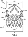
- FIG. 1 is a perspective view of a valve prosthesis 100 subject to radial interference at a proximal end. Radial interference can constrain or cause a change in the diameter of a portion of valve prosthesis 100.
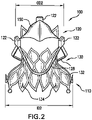
- FIG. 2 is a perspective view of valve prosthesis 100 not subject to radial interference at a proximal end.
- Valve prosthesis 100 includes an inflow section 110 at a proximal end thereof, and an outflow section 120 at a distal end thereof.
- Valve prosthesis 100 also includes a valve prosthesis support structure 130.
- Valve prosthesis support structure 130 includes posts 122 (also referred to as commissural posts) proximate to outflow section 120, and a proximal skirt 132 extending from inflow section 110 toward posts 122.
- Valve prosthesis 100 is preferably collapsible in order to facilitate transcatheter delivery.
- valve prosthesis 100 can be delivered via a transfemoral approach.
- Valve prosthesis 100 can also be delivered, however, by other transvascular approach methods or a transapical approach.
- Valve prosthesis 100 can also be implanted by open heart surgery or related methods.
- the valve prosthesis 100 can expand radially upon delivery at a target site.
- the target site is preferably the native aortic annulus of a subject, but it is understood that valves according to the present invention could be implanted at other positions in a subject (e.g., a native mitral or pulmonary annulus).
- distal tip of a catheter sheath containing prosthesis 100 can be inserted into a patient's vasculature (e.g., via a body lumen such as a femoral artery) and advanced (along a guide wire, if provided) to the position of a native annulus.
- the native leaflets of the annulus can be in place at the time of implantation of prosthesis 100, or can be partially or completely removed prior to implantation.
- An outer tube of the catheter can be withdrawn some distance to expose a proximal portion of proximal skirt 132. The proximal portion can be positioned so as to abut against the ventricular side of the aortic annulus.
- barbs 134 can be primary contact points of prosthesis 100 with an interior of a valve retaining sleeve, thereby reducing friction that could be caused by the inner surface of the valve retaining sleeve sliding over prosthesis 100 while prosthesis 100 moves with respect to the catheter sheath.
- Prosthesis support structure 130 can be made of a self-expanding material, e.g., nitinol, thus tending toward a fully expanded position that is sufficient to securely engage the native annulus. When in position within a patient, this tendency creates a radial force between prosthesis support structure 130 and the patient's anatomy, thus helping to hold valve prosthesis 100 in place.
- the pressure applied by the prosthesis support structure 130 need not be sufficient by itself to anchor the prosthesis 100 in the native annulus.
- Further inhibiting migration of valve prosthesis 100 can be axial support arms 128, which protrude over the tips of the native leaflets to provide axial support to valve prosthesis 100 and to prevent valve prosthesis 100 from being forced into the ventricle through the native leaflets during the cardiac cycle. Support arms 128 can take on a variety of configurations.
- inflow section 110 can engage the ventricle below the inflow end of the native annulus, providing additional anchoring.
- Support arms 128 can, for example, be configured to be at least partially disposed within aortic sinuses of the subject, and, for some applications, to engage and/or rest against floors of the aortic sinuses, and to apply an axial force directed toward a left ventricle of the subject.
- Support arms 128 can meet one another at junctures.
- the support arms can be mechanically engaged to one another where they meet at the junctures.
- support arms 128 meet one another without actually touching one another, and instead meet via an area defined at each juncture.
- the support arms are configured to define peaks at the junctures, and troughs between adjacent peaks.
- valve prosthesis 100 includes three posts 122, arranged circumferentially around a central longitudinal axis of valve prosthesis 100, and a flared portion extending in a proximal direction from posts 122.
- valve prosthesis 100 includes more or fewer than three posts 122, such as, for example, two posts 122, or four posts 122. Approximately 90% of humans have exactly three aortic sinuses. The three posts 122 provided in some exemplary embodiments correspond to these three aortic sinuses. For implantation in the approximately 10% of patients that have exactly two aortic sinuses, valve prosthesis 100 can include only two posts 122.
- Valve prosthesis 100 can also include a valve 150 coupled to posts 122.
- Valve 150 can be formed of a pliant material configured to collapse inwardly (i.e., towards the central longitudinal axis of valve prosthesis 100) during diastole, in order to inhibit retrograde blood flow, and to open outwardly during systole, to allow blood flow through valve prosthesis 100.
- Valve 150 can be formed of artificial or natural tissue.
- valve 150 can be formed of bovine or porcine pericardium, or of any suitable synthetic material.
- FIG. 2 is a perspective view of valve prosthesis 100 in an expanded state, wherein no inward radial pressure or interference is applied to inflow section 110.
- inflow section 110 has a diameter ID2
- outflow section 120 has an outflow diameter OD2.
- FIG. 1 is a perspective view of a valve prosthesis 100 that is subject to inward radial pressure or interference at inflow section 110.
- inflow section 110 will often be in at least a somewhat compressed position as shown in FIG. 1 due to the radial interference at inflow section 110.
- outflow section 120 has an outflow diameter OD1 that is larger than OD2, causing posts 122 to be positioned farther from one another than in a relaxed state.
- the outflow diameter of valve prosthesis 100 at outflow section 120 and the positioning of posts 122 are affected by radial interference on valve prosthesis 100 at inflow section 110, which can result in decreased performance characteristics of valve prosthesis 100.
- Decoupling of radial motion of outflow section 120 from radial interference at inflow section 110 can produce significant benefits by providing more predictable and stable valve geometry regardless of patient-specific anatomy.
- Fig. 3 is a perspective view of a valve prosthesis not falling within the scope of the claims.
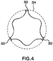
- FIG. 4 is a top schematic view of valve prosthesis 300.
- the basic structure of valve prosthesis 300 is generally similar to valve prosthesis 100.
- Valve prosthesis 300 includes an inflow section 310 at a proximal end thereof, and an outflow section 320 at a distal end thereof.
- Valve prosthesis support structure 330 includes posts 322 proximate to outflow section 320, and a proximal skirt 332 extending from inflow section 310 towards posts 322.
- Valve prosthesis 300 also includes a valve prosthesis support structure 330.
- Valve prosthesis 300 further includes a motion limiting member 324.
- Motion limiting member 324 includes a substantially rigid circular frame disposed around outflow section 320.
- the substantially rigid circular frame preferably substantially maintains its shape even when subjected to outside forces such as can be present within a body lumen of a patient.
- the substantially rigid circular frame can be made of, for example, the types of surgical steel traditionally used for making stent devices.
- Motion is limiting member 324 is mounted to valve prosthesis support structure 330 by being attached to distal ends of posts 322. In such a configuration, motion limiting member 324 prevents divergence of posts 322 by limiting the maximum diameter of outflow section 320, thereby preventing motion of posts 322 beyond the limits imposed by motion limiting member 324.
- Motion limiting member 324 can be constructed of a variety of materials, for example, nitinol.
- the rigid circular frame of motion limiting member 324 can, however, be sufficiently flexible to be compatible with collapse of valve prosthesis 300 during an insertion process.
- valve prosthesis 300 maintains predictable and stable valve geometry regardless of patient-specific anatomy.
- FIG. 5 is a perspective view of a valve prosthesis not falling within the scope of the claims.
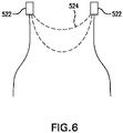
- FIG. 6 is a side schematic view of valve prosthesis 500. Description of elements of the prosthesis depicted in FIGS. 5 and 6 that are the same or operate similarly as the prosthesis described above may be omitted or abbreviated.
- Valve prosthesis 500 includes an inflow section 510 at a proximal end thereof, and an outflow section 520 at a distal end thereof.
- Valve prosthesis 500 also includes a valve prosthesis support structure 530, and a motion limiting member 524.
- Valve prosthesis support structure 530 includes posts 522 proximate to outflow section 520, and a proximal skirt 532 extending from inflow section 510 toward posts 522.
- Motion limiting member 524 includes rigid arches disposed proximate to outflow section 520. Each rigid arch is mounted to valve prosthesis support structure 530 by being attached to proximal ends of two adjacent posts 522. In this way, the rigid arches of the motion limiting member 524 together extend around outflow section 520. In such a configuration, motion limiting member 524 prevents divergence of posts 522 by limiting the diameter of outflow section 520, thereby preventing motion of posts 522 beyond the limits imposed by motion limiting member 524.
- the rigid arches of motion limiting member 524 can together form a circular shape, or can form another shape, such as, for example, a series of linked "humps" connecting around outflow section 520.
- the rigid arches of motion limiting member 524 are sufficiently flexible to collapse with valve prosthesis 500 during an insertion process.
- the rigid arches of motion limiting member 524 are mounted to valve prosthesis support structure 530 by being attached to distal ends of posts 522, or at intermediate positions of posts 522, in between proximal and distal ends.
- the rigid arches of motion limiting member 524 can extend out from valve prosthesis support structure 530 at a 90 degree angle with respect to a longitudinal axis extending through valve prosthesis 500.
- the rigid arches of motion limiting member 524 can extend from valve prosthesis support structure 530 at an angle other than 90 degrees, such as, for example, approximately 30 degrees, approximately 45 degrees, or approximately 120 degrees.
- each rigid arch need not extend out from valve prosthesis support structure 530 at the same angle as other rigid arches.
- multiple rigid arches can extend between adjacent posts 522. Intermediate connections can be formed between adjacent rigid arches such that the rigid arches extending between adjacent posts 522 are connected in series.
- valve prosthesis 500 maintains predictable and stable valve geometry regardless of patient-specific anatomy.
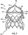
- FIG. 7 is a perspective view of a valve prosthesis 700 according to an embodiment of the present invention.
- FIG. 8 is a side schematic view of valve prosthesis 700. Description of elements of the embodiment depicted in FIGS. 7 and 8 that are the same or operate similarly as the prosthesis described above may be omitted or abbreviated.
- Valve prosthesis 700 includes an inflow section 710 at a proximal end thereof, and an outflow section 720 at a distal end thereof. Valve prosthesis 700 also includes a valve prosthesis support structure 730, and a motion limiting member 724.
- Valve prosthesis support structure 730 includes posts 722 proximate to outflow section 720, and a proximal skirt 732 extending from posts 722 toward inflow section 710.
- Motion limiting member 724 includes linear support elements disposed proximate to outflow section 720. Each linear support element is mounted to valve prosthesis support structure 730 by being attached to distal ends of two adjacent posts 722. In this way, the linear support elements of motion limiting member 724 together link posts 722. In such a configuration, motion limiting member 724 prevents divergence of posts 722 by limiting the diameter of outflow section 720, thereby preventing motion of posts 722 beyond the limits imposed by motion limiting member 724.
- multiple linear support sub-elements can extend between adjacent posts 722, with intermediate connections between adjacent linear support sub-elements such that the linear support sub-elements extending between adjacent posts 722 are connected in series.
- valve prosthesis 700 maintains predictable and stable valve geometry regardless
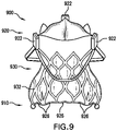
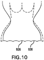
- FIG. 9 is a perspective view of an exemplary valve prosthesis 900 not falling under the scope of the claims.
- FIG. 10 is a side schematic view of valve prosthesis 900. Description of elements of the prosthesis depicted in FIGS. 9 and 10 that are the same or operate similarly as the embodiments described above may be omitted or abbreviated.
- Valve prosthesis 900 includes an inflow section 910 at a proximal end thereof, and an outflow section 920 at a distal end thereof. Valve prosthesis 900 also includes a valve prosthesis support structure 930, and a motion limiting member 926.
- Valve prosthesis support structure 930 includes posts 922 proximate to outflow section 920, and a proximal skirt 932 extending from inflow section 910 toward posts 922.
- Motion limiting member 926 includes strut support elements disposed proximate to inflow section 910. Each strut support element is mounted to a proximal end of inflow section 910, and extends between adjacent endpoints of proximal skirt 932. In this way, the strut support elements of motion limiting member 926 together link endpoints of inflow section 910. In such a configuration, motion limiting member 926 prevents divergence of the endpoints of proximal skirt 932 by limiting the diameter of inflow section 910, thereby preventing motion of the endpoints of proximal skirt 932 beyond the limits imposed by motion limiting member 926.
- multiple strut support elements can extend between adjacent endpoints of proximal skirt 932, with intermediate connections between adjacent endpoints of proximal skirt 932 such that the strut support elements extending between adjacent endpoints of proximal skirt 932 are connected in series.
- strut support members of motion limiting member 926 are incorporated in and form a part of proximal skirt 932 such that motion limiting member 926 and proximal skirt 932 are formed together monolithically.
- the strut support members of motion limiting member 926 are rigid. In some embodiments, the strut support members of motion limiting member are non-rigid.
- inflow section 910 is limited by motion limiting member 926, its motion due to valve function and cardiac contraction can be confined to within limits necessary for proper functioning, thereby eliminating or reducing unnecessary radial movement. Reducing this unnecessary radial movement in turn reduces the fatigue that valve prosthesis 900 is subject to, thereby extending its useful life, and eliminating the need for subsequent replacement of valve prosthesis 900 or reducing the frequency with which valve prosthesis 900 must be replaced to maintain proper functionality. Additionally, because motion limiting member 926 limits the diameter of inflow section 910, valve prosthesis 900 maintains more predictable and stable valve motion and valve geometry regardless of patient-specific anatomy. Further, stabilizing the diameter of inflow section 910 results in less deformation (i.e., changes in diameter) of outflow section 920.
- Fig. 11 is a perspective view of a valve prosthesis 1100 not falling under the scope of the claims. not showing all features of the claimed invention. Description of elements of the prosthesis depicted in FIG. 11 that are the same or operate similarly as those described above may be omitted or abbreviated.
- Valve prosthesis 1100 includes an inflow section 1110 at a proximal end thereof, and an outflow section 1120 at a distal end thereof. Valve prosthesis 1100 also includes a valve prosthesis support structure 1130, and sealing members 1142.
- Valve prosthesis support structure 1130 includes posts 1122 proximate to outflow section 1120, and a proximal skirt 1132 extending from posts 1122 toward inflow section 1110.
- Sealing members 1142 can be disposed proximate to inflow section 1110, and can be positioned to correspond radially with posts 1122. Such positioning corresponds to native commissures, and aligns sealing members 1142 with a patient's inter-leaflet triangles. Sealing members 1142 can be shaped so as to fit into the inter-leaflet triangles, or can be formed of a material that conforms to the shape of the inter-leaflet triangles upon being placed in contact with the inter-leaflet triangles. In this way, sealing members 1142 help valve prosthesis 1100 attain a high level of conformance to the patient's annular anatomy, thereby preventing or reducing the chance and severity of paravalvular leakage.
- U.S. Application No. 13/091,765, filed April 21, 2011 discusses sealing members for use with prosthetic valves.
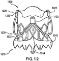
- Fig. 12 is a perspective view of an exemplary valve prosthesis 1200 not falling under the scope of the claims. Description of elements of the prosthesis depicted in FIG. 12 that are the same or operate similarly as those described above may be omitted or abbreviated.
- Valve prosthesis 1200 includes an inflow section 1210 at a proximal end thereof, and an outflow section 1220 at a distal end thereof. Valve prosthesis 1200 also includes a valve prosthesis support structure 1230, and a sealing member 1242.
- Valve prosthesis support structure 1230 includes posts 1222 proximate to outflow section 1220, and a proximal skirt 1232 extending from posts 1222 toward inflow section 1210.
- Sealing member 1242 can be disposed proximate to inflow section 1210, and can extend around the circumference of proximal skirt 1232. Sealing member 1242 can include sealing tips 1244 positioned to correspond radially with posts 1222. Such positioning corresponds to native commissures, and aligns sealing tips 1244 with a patient's inter-leaflet triangles. Sealing tips 1244 can be shaped so as to fit into the inter-leaflet triangles, or can be formed of a material that conforms to the shape of the inter-leaflet triangles upon being placed in contact with the inter-leaflet triangles. In this way, sealing member 1242, including sealing tips 1244, helps valve prosthesis 1200 attain a high level of conformance to the patient's annular anatomy, thereby preventing or reducing the chance and severity of paravalvular leakage.
- sealing member 1242 including sealing tips 1244 is formed of a single material.
- sealing tips 1244 are formed of a material different from the balance of sealing member 1242.
- sealing tips 1244 can be formed of a soft material capable of conforming to the patient's inter-leaflet triangles, while the balance of sealing member 1242 can be formed of a more rigid material.
- sealing member 1242 acts as a motion limiting member, and limits the diameter of inflow section 1210, thereby preventing motion of endpoints of proximal skirt 1232 beyond limits imposed by sealing member 1242. In this way, sealing member 1242 is similar to motion limiting member 926.
Description
- The present invention relates to prosthetic valves More particularly, the present invention provides for prosthetic valve support structures configured for transcatheter delivery.
- Aortic valve replacement in patients with severe valve disease is a common surgical procedure. The replacement is conventionally performed by open heart surgery, in which the heart is usually arrested and the patient is placed on a heart bypass machine. Prostheses including prosthetic heart valves have been developed that are implanted using minimally invasive procedures such as transapical or percutaneous approaches. These methods involve compressing the prosthesis radially to reduce its diameter, inserting the prosthesis into a delivery tool, such as a catheter, and advancing the delivery tool to the correct anatomical position in the heart. Once properly positioned, the prosthesis is deployed by radial expansion within the native valve annulus.
- Such a prosthesis can include a support structure to maintain the prosthetic heart valve in place. The inflow section of the prosthesis can be subject to radial interference from a body lumen, such as the left ventricular outflow tract (LVOT), that can exert circumferential radial pressure on the prosthesis. Such radial interference at an inflow section of the prosthesis can result in radial movement at an outflow section of the prosthesis. Such movement may be undesirable.
- Moreover, a prosthesis can be subject to radial movement at an inflow section, due to, for example, valve function and cardiac contraction. Such radial movement can cause the diameter of the inflow section to experience cyclical contraction and expansion. Such contraction and expansion can subject the prosthesis to unnecessary fatigue.
- Additionally, due to less than perfect conformance between the geometries of a patient's anatomy and the prosthesis, paravalvular leakage can occur. For example, a major course of leakage between a prosthesis and the LVOT wall is due to spaces created between scalloped leaflets called inter-leaflet triangles.
- Accordingly, there is a need for a prosthesis that provides decoupled radial motion of the outflow section and the inflow section, and that better conforms to a patient's anatomy.
-
PCT Publication No. WO 05/002466 to Schwammenthal et al. -
PCT Publication No. WO 06/070372 to Schwammenthal et al. -
US Patent Application Publication No. 2006/0149360 to Schwammenthal et al. , describes a prosthetic device including a valve-orifice attachment member attachable to a valve in a blood vessel and including a fluid inlet, and a diverging member that extends from the fluid inlet, the diverging member including a proximal end near the fluid inlet and a distal end distanced from the proximal end. A distal portion of the diverging member has a larger cross-sectional area for fluid flow therethrough than a proximal portion thereof. -
US Patent Application Publication No. 2006/0259136 to Nguyen et al. , describes a heart valve prosthesis having a self-expanding multi-level frame that supports a valve body including a skirt and plurality of coapting leaflets. The frame transitions between a contracted delivery configuration that enables percutaneous transluminal delivery, and an expanded deployed configuration having an asymmetric hourglass shape. The valve body skirt and leaflets are constructed so that the center of coaptation can be selected to reduce horizontal forces applied to the commissures of the valve, and to efficiently distribute and transmit forces along the leaflets and to the frame. Alternatively, the valve body can be used as a surgically implantable replacement valve prosthesis. - Document
US 2005/075584 A1 relates to a minimally invasive valve replacement system. - Document
US 2005/043790 A1 relates to a kit enabling a prosthetic valve to be placed in a body enabling a prosthetic valve to be put into place in a duct in the body. - Document
WO 03/047468 A1 - Document
US 2001/000188 A1 relates to limited expansion endoluminal prostheses and methods for their use. - Document
WO 2008/070797 A2 relates to a system and method for transapical delivery of an annulus anchored self-expanding valve. - Document
US 2008/103586 A1 relates to an implant for placing in a blood circulation conduit. - The present invention is defined in claim 1.
- The present invention provides a valve prosthesis support structure that limits radial motion at a distal end thereof.
- The present invention also provides a valve prosthesis support structure that limits radial motion at a proximal end thereof.
- Further disclosed is a valve prosthesis support structure that includes sealing members to prevent paravalvular leakage.
- The present invention provides a prosthesis including a support structure having a proximal end and a distal end, and a motion limiting member attached to the distal end of the support structure, wherein the motion limiting member is configured to restrict radial expansion of the distal end of the support structure.
- Further disclosed is a valve prosthesis support structure, including a collapsible and expandable support structure including a plurality of posts at a distal end thereof and a flared portion extending in a proximal direction from the plurality of posts, and a motion limiting member attached to a proximal end of the proximal skirt, wherein the motion limiting member is configured to restrict radial movement of the proximal end of the collapsible support structure.
- Further disclosed is a method of delivering a prosthesis to a desired location in a body. One such method includes introducing a sheath of a delivery system into a subject's vasculature, wherein a distal tip of the sheath contains the prosthesis, advancing the distal tip of the sheath to the desired location in the body, and releasing the prosthesis within the body, wherein the prosthesis includes a support structure having a proximal end and a distal end, and a motion limiting member attached to the distal end of the support structure.
- Additional features of the invention will be set forth in the description that follows. Both the foregoing general description and the following detailed description are exemplary and explanatory and are intended to provide further explanation of the invention as claimed.
- The accompanying figures, which are incorporated herein, form part of the specification and illustrate exemplary embodiments of the present invention. Together with the description, the figures further serve to explain the principles of and to enable a person skilled in the relevant art(s) to make and use the exemplary embodiments described herein. In the drawings like reference characters indicate identical or functionally similar elements.
Figs. 1-6 and9-12 do not show all features of the claimed invention. -
FIG. 1 is a perspective view of a valve prosthesis subject to radial interference at a proximal end. -
FIG. 2 is a perspective view of a valve prosthesis not subject to radial interference at a proximal end. -
FIG. 3 is a perspective view of a valve prosthesis -
FIG. 4 is a top schematic view of the valve prosthesis ofFIG. 3 . -
FIG. 5 is a perspective view of a valve prosthesis -
FIG. 6 is a side schematic view of the valve prosthesis ofFIG. 5 . -
FIG. 7 is a perspective view of a valve prosthesis according to an embodiment of the present invention. -
FIG. 8 is a top schematic view of the valve prosthesis ofFIG. 7 . -
FIG. 9 is a perspective view of a valve prosthesis -
FIG. 10 is a side schematic view of the valve prosthesis ofFIG. 9 . -
FIG. 11 is a perspective view of a valve prosthesis -
FIG. 12 is a perspective view of a valve prosthesis - The following detailed description of the present invention refers to the
-
FIG. 1 is a perspective view of avalve prosthesis 100 subject to radial interference at a proximal end. Radial interference can constrain or cause a change in the diameter of a portion ofvalve prosthesis 100.FIG. 2 is a perspective view ofvalve prosthesis 100 not subject to radial interference at a proximal end.Valve prosthesis 100 includes aninflow section 110 at a proximal end thereof, and anoutflow section 120 at a distal end thereof.Valve prosthesis 100 also includes a valveprosthesis support structure 130. - Valve
prosthesis support structure 130 includes posts 122 (also referred to as commissural posts) proximate tooutflow section 120, and aproximal skirt 132 extending frominflow section 110 towardposts 122. -
Valve prosthesis 100 is preferably collapsible in order to facilitate transcatheter delivery. Preferably,valve prosthesis 100 can be delivered via a transfemoral approach.Valve prosthesis 100 can also be delivered, however, by other transvascular approach methods or a transapical approach.Valve prosthesis 100 can also be implanted by open heart surgery or related methods. Thevalve prosthesis 100 can expand radially upon delivery at a target site. The target site is preferably the native aortic annulus of a subject, but it is understood that valves according to the present invention could be implanted at other positions in a subject (e.g., a native mitral or pulmonary annulus). - For example, distal tip of a catheter
sheath containing prosthesis 100 can be inserted into a patient's vasculature (e.g., via a body lumen such as a femoral artery) and advanced (along a guide wire, if provided) to the position of a native annulus. The native leaflets of the annulus can be in place at the time of implantation ofprosthesis 100, or can be partially or completely removed prior to implantation. An outer tube of the catheter can be withdrawn some distance to expose a proximal portion ofproximal skirt 132. The proximal portion can be positioned so as to abut against the ventricular side of the aortic annulus. If provided,barbs 134 can be primary contact points ofprosthesis 100 with an interior of a valve retaining sleeve, thereby reducing friction that could be caused by the inner surface of the valve retaining sleeve sliding overprosthesis 100 whileprosthesis 100 moves with respect to the catheter sheath. Once it is determined thatprosthesis 100 is properly positioned in the annulus, the outer tube can be fully withdrawn, releasingvalve prosthesis 100 and allowing radial expansion ofvalve prosthesis 100 to engage the annulus. If, after partial release, it is determined that the prosthesis is not properly positioned, theinflow section 110 can be recaptured into the outer tube for repositioning. -
Prosthesis support structure 130 can be made of a self-expanding material, e.g., nitinol, thus tending toward a fully expanded position that is sufficient to securely engage the native annulus. When in position within a patient, this tendency creates a radial force betweenprosthesis support structure 130 and the patient's anatomy, thus helping to holdvalve prosthesis 100 in place. The pressure applied by theprosthesis support structure 130, however, need not be sufficient by itself to anchor theprosthesis 100 in the native annulus. Further inhibiting migration ofvalve prosthesis 100 can beaxial support arms 128, which protrude over the tips of the native leaflets to provide axial support tovalve prosthesis 100 and to preventvalve prosthesis 100 from being forced into the ventricle through the native leaflets during the cardiac cycle.Support arms 128 can take on a variety of configurations. Further, as detailed above,inflow section 110 can engage the ventricle below the inflow end of the native annulus, providing additional anchoring. -
Support arms 128 can, for example, be configured to be at least partially disposed within aortic sinuses of the subject, and, for some applications, to engage and/or rest against floors of the aortic sinuses, and to apply an axial force directed toward a left ventricle of the subject.Support arms 128 can meet one another at junctures. For applications in which each ofsupport arms 128 is fabricated as a separate piece, the support arms can be mechanically engaged to one another where they meet at the junctures. For some applications, supportarms 128 meet one another without actually touching one another, and instead meet via an area defined at each juncture. Typically, the support arms are configured to define peaks at the junctures, and troughs between adjacent peaks.U.S. Application No. 11/728,253, filed March 23, 2007 U.S. Application No. 11/726,889, filed March 23, 2007 - In some exemplary embodiments,
valve prosthesis 100 includes threeposts 122, arranged circumferentially around a central longitudinal axis ofvalve prosthesis 100, and a flared portion extending in a proximal direction from posts 122. In some exemplary embodiments,valve prosthesis 100 includes more or fewer than threeposts 122, such as, for example, twoposts 122, or fourposts 122. Approximately 90% of humans have exactly three aortic sinuses. The threeposts 122 provided in some exemplary embodiments correspond to these three aortic sinuses. For implantation in the approximately 10% of patients that have exactly two aortic sinuses,valve prosthesis 100 can include only twoposts 122. -
Valve prosthesis 100 can also include avalve 150 coupled to posts 122.Valve 150 can be formed of a pliant material configured to collapse inwardly (i.e., towards the central longitudinal axis of valve prosthesis 100) during diastole, in order to inhibit retrograde blood flow, and to open outwardly during systole, to allow blood flow throughvalve prosthesis 100.Valve 150 can be formed of artificial or natural tissue. For example,valve 150 can be formed of bovine or porcine pericardium, or of any suitable synthetic material. -
FIG. 2 is a perspective view ofvalve prosthesis 100 in an expanded state, wherein no inward radial pressure or interference is applied toinflow section 110. In this expanded state,inflow section 110 has a diameter ID2, andoutflow section 120 has an outflow diameter OD2.FIG. 1 is a perspective view of avalve prosthesis 100 that is subject to inward radial pressure or interference atinflow section 110. Depending on the geometry of a particular subject's annulus,inflow section 110 will often be in at least a somewhat compressed position as shown inFIG. 1 due to the radial interference atinflow section 110. In this position,outflow section 120 has an outflow diameter OD1 that is larger than OD2, causingposts 122 to be positioned farther from one another than in a relaxed state. In other words, the outflow diameter ofvalve prosthesis 100 atoutflow section 120 and the positioning ofposts 122 are affected by radial interference onvalve prosthesis 100 atinflow section 110, which can result in decreased performance characteristics ofvalve prosthesis 100. - Decoupling of radial motion of
outflow section 120 from radial interference atinflow section 110 can produce significant benefits by providing more predictable and stable valve geometry regardless of patient-specific anatomy. -
Fig. 3 is a perspective view of a valve prosthesis not falling within the scope of the claims. - not showing all features of the claimed invention. of.
FIG. 4 is a top schematic view ofvalve prosthesis 300. The basic structure ofvalve prosthesis 300 is generally similar tovalve prosthesis 100.Valve prosthesis 300 includes aninflow section 310 at a proximal end thereof, and anoutflow section 320 at a distal end thereof. Valveprosthesis support structure 330 includesposts 322 proximate tooutflow section 320, and aproximal skirt 332 extending frominflow section 310 towardsposts 322.Valve prosthesis 300 also includes a valveprosthesis support structure 330. -
Valve prosthesis 300 further includes amotion limiting member 324.Motion limiting member 324 includes a substantially rigid circular frame disposed aroundoutflow section 320. The substantially rigid circular frame preferably substantially maintains its shape even when subjected to outside forces such as can be present within a body lumen of a patient. The substantially rigid circular frame can be made of, for example, the types of surgical steel traditionally used for making stent devices. Motion is limitingmember 324 is mounted to valveprosthesis support structure 330 by being attached to distal ends ofposts 322. In such a configuration,motion limiting member 324 prevents divergence ofposts 322 by limiting the maximum diameter ofoutflow section 320, thereby preventing motion ofposts 322 beyond the limits imposed bymotion limiting member 324.Motion limiting member 324 can be constructed of a variety of materials, for example, nitinol. - The rigid circular frame of
motion limiting member 324 can, however, be sufficiently flexible to be compatible with collapse ofvalve prosthesis 300 during an insertion process. - Because the diameter of
outflow section 320 is limited bymotion limiting member 324, the diameter ofoutflow section 320 is not substantially affected by changes in the diameter ofinflow section 310, thereby decoupling radial motion ofoutflow section 320 from radial interference atinflow section 310. Thus,valve prosthesis 300 maintains predictable and stable valve geometry regardless of patient-specific anatomy. -
Fig. 5 is a perspective view of a valve prosthesis not falling within the scope of the claims.FIG. 6 is a side schematic view ofvalve prosthesis 500. Description of elements of the prosthesis depicted inFIGS. 5 and6 that are the same or operate similarly as the prosthesis described above may be omitted or abbreviated. -
Valve prosthesis 500 includes aninflow section 510 at a proximal end thereof, and anoutflow section 520 at a distal end thereof.Valve prosthesis 500 also includes a valveprosthesis support structure 530, and amotion limiting member 524. Valveprosthesis support structure 530 includesposts 522 proximate tooutflow section 520, and aproximal skirt 532 extending frominflow section 510 towardposts 522. -
Motion limiting member 524 includes rigid arches disposed proximate tooutflow section 520. Each rigid arch is mounted to valveprosthesis support structure 530 by being attached to proximal ends of twoadjacent posts 522. In this way, the rigid arches of themotion limiting member 524 together extend aroundoutflow section 520. In such a configuration,motion limiting member 524 prevents divergence ofposts 522 by limiting the diameter ofoutflow section 520, thereby preventing motion ofposts 522 beyond the limits imposed bymotion limiting member 524. - In some examples the rigid arches of
motion limiting member 524 can together form a circular shape, or can form another shape, such as, for example, a series of linked "humps" connecting aroundoutflow section 520. - In some examples, the rigid arches of
motion limiting member 524 are sufficiently flexible to collapse withvalve prosthesis 500 during an insertion process. - In some examples, the rigid arches of
motion limiting member 524 are mounted to valveprosthesis support structure 530 by being attached to distal ends ofposts 522, or at intermediate positions ofposts 522, in between proximal and distal ends. - In some examples, the rigid arches of
motion limiting member 524 can extend out from valveprosthesis support structure 530 at a 90 degree angle with respect to a longitudinal axis extending throughvalve prosthesis 500. Alternatively, the rigid arches ofmotion limiting member 524 can extend from valveprosthesis support structure 530 at an angle other than 90 degrees, such as, for example, approximately 30 degrees, approximately 45 degrees, or approximately 120 degrees. Moreover, each rigid arch need not extend out from valveprosthesis support structure 530 at the same angle as other rigid arches. - In some examples multiple rigid arches can extend between
adjacent posts 522. Intermediate connections can be formed between adjacent rigid arches such that the rigid arches extending betweenadjacent posts 522 are connected in series. - Because the diameter of
outflow section 520 is limited bymotion limiting member 524, it is not substantially affected by radial interference (i.e., changes in diameter) atinflow section 510, thereby achieving decoupling of radial motion ofoutflow section 520 from radial interference atinflow section 510. Thus,valve prosthesis 500 maintains predictable and stable valve geometry regardless of patient-specific anatomy. -
FIG. 7 is a perspective view of avalve prosthesis 700 according to an embodiment of the present invention.FIG. 8 is a side schematic view ofvalve prosthesis 700. Description of elements of the embodiment depicted inFIGS. 7 and8 that are the same or operate similarly as the prosthesis described above may be omitted or abbreviated. -
Valve prosthesis 700 includes aninflow section 710 at a proximal end thereof, and anoutflow section 720 at a distal end thereof.Valve prosthesis 700 also includes a valveprosthesis support structure 730, and amotion limiting member 724. - Valve
prosthesis support structure 730 includesposts 722 proximate tooutflow section 720, and aproximal skirt 732 extending fromposts 722 towardinflow section 710. -
Motion limiting member 724 includes linear support elements disposed proximate tooutflow section 720. Each linear support element is mounted to valveprosthesis support structure 730 by being attached to distal ends of twoadjacent posts 722. In this way, the linear support elements ofmotion limiting member 724 together link posts 722. In such a configuration,motion limiting member 724 prevents divergence ofposts 722 by limiting the diameter ofoutflow section 720, thereby preventing motion ofposts 722 beyond the limits imposed bymotion limiting member 724. - In some embodiments multiple linear support sub-elements can extend between
adjacent posts 722, with intermediate connections between adjacent linear support sub-elements such that the linear support sub-elements extending betweenadjacent posts 722 are connected in series. - Because the diameter of
outflow section 720 is limited bymotion limiting member 724, it is preferably not substantially affected by radial interference (i.e., changes in diameter) atinflow section 710, thereby achieving decoupling of radial motion ofoutflow section 720 from radial interference atinflow section 710. Thus,valve prosthesis 700 maintains predictable and stable valve geometry regardless - of patient-specific anatomy.
Fig. 9 is a perspective view of anexemplary valve prosthesis 900 not falling under the scope of the claims.FIG. 10 is a side schematic view ofvalve prosthesis 900. Description of elements of the prosthesis depicted inFIGS. 9 and10 that are the same or operate similarly as the embodiments described above may be omitted or abbreviated. -
Valve prosthesis 900 includes aninflow section 910 at a proximal end thereof, and anoutflow section 920 at a distal end thereof.Valve prosthesis 900 also includes a valveprosthesis support structure 930, and amotion limiting member 926. - Valve
prosthesis support structure 930 includesposts 922 proximate tooutflow section 920, and aproximal skirt 932 extending frominflow section 910 towardposts 922. -
Motion limiting member 926 includes strut support elements disposed proximate toinflow section 910. Each strut support element is mounted to a proximal end ofinflow section 910, and extends between adjacent endpoints ofproximal skirt 932. In this way, the strut support elements ofmotion limiting member 926 together link endpoints ofinflow section 910. In such a configuration,motion limiting member 926 prevents divergence of the endpoints ofproximal skirt 932 by limiting the diameter ofinflow section 910, thereby preventing motion of the endpoints ofproximal skirt 932 beyond the limits imposed bymotion limiting member 926. - In some examples, multiple strut support elements can extend between adjacent endpoints of
proximal skirt 932, with intermediate connections between adjacent endpoints ofproximal skirt 932 such that the strut support elements extending between adjacent endpoints ofproximal skirt 932 are connected in series. - In some examples the strut support members of
motion limiting member 926 are incorporated in and form a part ofproximal skirt 932 such thatmotion limiting member 926 andproximal skirt 932 are formed together monolithically. - In some examples, the strut support members of
motion limiting member 926 are rigid. In some embodiments, the strut support members of motion limiting member are non-rigid. - Because the diameter of
inflow section 910 is limited bymotion limiting member 926, its motion due to valve function and cardiac contraction can be confined to within limits necessary for proper functioning, thereby eliminating or reducing unnecessary radial movement. Reducing this unnecessary radial movement in turn reduces the fatigue thatvalve prosthesis 900 is subject to, thereby extending its useful life, and eliminating the need for subsequent replacement ofvalve prosthesis 900 or reducing the frequency with whichvalve prosthesis 900 must be replaced to maintain proper functionality. Additionally, becausemotion limiting member 926 limits the diameter ofinflow section 910,valve prosthesis 900 maintains more predictable and stable valve motion and valve geometry regardless of patient-specific anatomy. Further, stabilizing the diameter ofinflow section 910 results in less deformation (i.e., changes in diameter) ofoutflow section 920. -
Fig. 11 is a perspective view of avalve prosthesis 1100 not falling under the scope of the claims. not showing all features of the claimed invention. Description of elements of the prosthesis depicted inFIG. 11 that are the same or operate similarly as those described above may be omitted or abbreviated. -
Valve prosthesis 1100 includes aninflow section 1110 at a proximal end thereof, and anoutflow section 1120 at a distal end thereof.Valve prosthesis 1100 also includes a valveprosthesis support structure 1130, and sealingmembers 1142. - Valve
prosthesis support structure 1130 includesposts 1122 proximate tooutflow section 1120, and aproximal skirt 1132 extending fromposts 1122 towardinflow section 1110. -
Sealing members 1142 can be disposed proximate toinflow section 1110, and can be positioned to correspond radially withposts 1122. Such positioning corresponds to native commissures, and aligns sealingmembers 1142 with a patient's inter-leaflet triangles.Sealing members 1142 can be shaped so as to fit into the inter-leaflet triangles, or can be formed of a material that conforms to the shape of the inter-leaflet triangles upon being placed in contact with the inter-leaflet triangles. In this way, sealingmembers 1142help valve prosthesis 1100 attain a high level of conformance to the patient's annular anatomy, thereby preventing or reducing the chance and severity of paravalvular leakage.U.S. Application No. 13/091,765, filed April 21, 2011 -
Fig. 12 is a perspective view of anexemplary valve prosthesis 1200 not falling under the scope of the claims. Description of elements of the prosthesis depicted inFIG. 12 that are the same or operate similarly as those described above may be omitted or abbreviated. -
Valve prosthesis 1200 includes aninflow section 1210 at a proximal end thereof, and anoutflow section 1220 at a distal end thereof.Valve prosthesis 1200 also includes a valveprosthesis support structure 1230, and a sealingmember 1242. - Valve
prosthesis support structure 1230 includesposts 1222 proximate tooutflow section 1220, and aproximal skirt 1232 extending fromposts 1222 towardinflow section 1210. -
Sealing member 1242 can be disposed proximate toinflow section 1210, and can extend around the circumference ofproximal skirt 1232.Sealing member 1242 can include sealingtips 1244 positioned to correspond radially withposts 1222. Such positioning corresponds to native commissures, and aligns sealingtips 1244 with a patient's inter-leaflet triangles.Sealing tips 1244 can be shaped so as to fit into the inter-leaflet triangles, or can be formed of a material that conforms to the shape of the inter-leaflet triangles upon being placed in contact with the inter-leaflet triangles. In this way, sealingmember 1242, including sealingtips 1244, helpsvalve prosthesis 1200 attain a high level of conformance to the patient's annular anatomy, thereby preventing or reducing the chance and severity of paravalvular leakage. - In some examples, sealing
member 1242 including sealingtips 1244 is formed of a single material. In some embodiments, sealingtips 1244 are formed of a material different from the balance of sealingmember 1242. For example, sealingtips 1244 can be formed of a soft material capable of conforming to the patient's inter-leaflet triangles, while the balance of sealingmember 1242 can be formed of a more rigid material. - In some examples, sealing
member 1242 acts as a motion limiting member, and limits the diameter ofinflow section 1210, thereby preventing motion of endpoints ofproximal skirt 1232 beyond limits imposed by sealingmember 1242. In this way, sealingmember 1242 is similar tomotion limiting member 926.
Claims (2)
- A valve prosthesis (300, 500, 700, 900) comprising:an inflow section (310) at a proximal end of the valve prosthesis and an outflow section (320) at a distal end of the valve prosthesis;a support structure (330, 530, 730, 930) having a proximal end and a distal end, wherein the support structure (330, 530, 730, 930) comprises a plurality of posts (322, 522, 722, 922) at a distal portion thereof;a motion limiting member (324, 524, 724, 926) attached to the distal end of the support structure,wherein the motion limiting member (324, 524, 724, 926) is configured to restrict radial expansion of the distal end of the support structure (330, 530, 730, 930) and to limit the diameter of outflow section (320), characterised in that the motion limiting member comprises linear support elements, each linear support element extending between adjacent posts (322, 522, 722, 922),wherein each linear support element is attached to distal ends of the adjacent posts (322, 522, 722, 922) and wherein each linear support element is rigid.
- The prosthesis (300, 500, 700, 900) of claim 1, wherein the motion limiting member (324, 524, 724, 926) is configured to limit radial movements of the plurality of posts (322, 522, 722, 922).
Priority Applications (1)
| Application Number | Priority Date | Filing Date | Title |
|---|---|---|---|
| EP22169380.7A EP4052682A1 (en) | 2010-09-01 | 2011-08-24 | Prosthetic valve support structure |
Applications Claiming Priority (2)
| Application Number | Priority Date | Filing Date | Title |
|---|---|---|---|
| US37911510P | 2010-09-01 | 2010-09-01 | |
| PCT/US2011/048988 WO2012030598A2 (en) | 2010-09-01 | 2011-08-24 | Prosthetic valve support structure |
Related Child Applications (1)
| Application Number | Title | Priority Date | Filing Date |
|---|---|---|---|
| EP22169380.7A Division EP4052682A1 (en) | 2010-09-01 | 2011-08-24 | Prosthetic valve support structure |
Publications (2)
| Publication Number | Publication Date |
|---|---|
| EP2611388A2 EP2611388A2 (en) | 2013-07-10 |
| EP2611388B1 true EP2611388B1 (en) | 2022-04-27 |
Family
ID=44759755
Family Applications (2)
| Application Number | Title | Priority Date | Filing Date |
|---|---|---|---|
| EP22169380.7A Pending EP4052682A1 (en) | 2010-09-01 | 2011-08-24 | Prosthetic valve support structure |
| EP11752405.8A Active EP2611388B1 (en) | 2010-09-01 | 2011-08-24 | Prosthetic valve support structure |
Family Applications Before (1)
| Application Number | Title | Priority Date | Filing Date |
|---|---|---|---|
| EP22169380.7A Pending EP4052682A1 (en) | 2010-09-01 | 2011-08-24 | Prosthetic valve support structure |
Country Status (7)
| Country | Link |
|---|---|
| US (4) | US9918833B2 (en) |
| EP (2) | EP4052682A1 (en) |
| JP (1) | JP5874727B2 (en) |
| CN (1) | CN103118629A (en) |
| AU (1) | AU2011296361B2 (en) |
| BR (1) | BR112013004962A2 (en) |
| WO (1) | WO2012030598A2 (en) |
Cited By (1)
| Publication number | Priority date | Publication date | Assignee | Title |
|---|---|---|---|---|
| US11617650B2 (en) | 2012-05-30 | 2023-04-04 | Neovasc Tiara Inc. | Methods and apparatus for loading a prosthesis onto a delivery system |
Families Citing this family (98)
| Publication number | Priority date | Publication date | Assignee | Title |
|---|---|---|---|---|
| US8870950B2 (en) | 2009-12-08 | 2014-10-28 | Mitral Tech Ltd. | Rotation-based anchoring of an implant |
| US20110224785A1 (en) * | 2010-03-10 | 2011-09-15 | Hacohen Gil | Prosthetic mitral valve with tissue anchors |
| US8579964B2 (en) | 2010-05-05 | 2013-11-12 | Neovasc Inc. | Transcatheter mitral valve prosthesis |
| US11653910B2 (en) | 2010-07-21 | 2023-05-23 | Cardiovalve Ltd. | Helical anchor implantation |
| US9763657B2 (en) | 2010-07-21 | 2017-09-19 | Mitraltech Ltd. | Techniques for percutaneous mitral valve replacement and sealing |
| US8992604B2 (en) | 2010-07-21 | 2015-03-31 | Mitraltech Ltd. | Techniques for percutaneous mitral valve replacement and sealing |
| US9132009B2 (en) | 2010-07-21 | 2015-09-15 | Mitraltech Ltd. | Guide wires with commissural anchors to advance a prosthetic valve |
| JP6010545B2 (en) | 2010-12-23 | 2016-10-19 | トゥエルヴ, インコーポレイテッド | System for mitral valve repair and replacement |
| US9308087B2 (en) | 2011-04-28 | 2016-04-12 | Neovasc Tiara Inc. | Sequentially deployed transcatheter mitral valve prosthesis |
| US9554897B2 (en) | 2011-04-28 | 2017-01-31 | Neovasc Tiara Inc. | Methods and apparatus for engaging a valve prosthesis with tissue |
| AU2012272855C1 (en) | 2011-06-21 | 2018-04-05 | Twelve, Inc. | Prosthetic heart valve devices and associated systems and methods |
| AU2012290221B2 (en) * | 2011-07-29 | 2017-02-23 | Carnegie Mellon University | Artificial valved conduits for cardiac reconstructive procedures and methods for their production |
| US8852272B2 (en) | 2011-08-05 | 2014-10-07 | Mitraltech Ltd. | Techniques for percutaneous mitral valve replacement and sealing |
| WO2013021374A2 (en) | 2011-08-05 | 2013-02-14 | Mitraltech Ltd. | Techniques for percutaneous mitral valve replacement and sealing |
| US20140324164A1 (en) | 2011-08-05 | 2014-10-30 | Mitraltech Ltd. | Techniques for percutaneous mitral valve replacement and sealing |
| WO2013021375A2 (en) | 2011-08-05 | 2013-02-14 | Mitraltech Ltd. | Percutaneous mitral valve replacement and sealing |
| US9039757B2 (en) | 2011-10-19 | 2015-05-26 | Twelve, Inc. | Prosthetic heart valve devices, prosthetic mitral valves and associated systems and methods |
| US9763780B2 (en) | 2011-10-19 | 2017-09-19 | Twelve, Inc. | Devices, systems and methods for heart valve replacement |
| US9655722B2 (en) | 2011-10-19 | 2017-05-23 | Twelve, Inc. | Prosthetic heart valve devices, prosthetic mitral valves and associated systems and methods |
| CN107028685B (en) | 2011-10-19 | 2019-11-15 | 托尔福公司 | Artificial heart valve film device, artificial mitral valve and related systems and methods |
| US11202704B2 (en) | 2011-10-19 | 2021-12-21 | Twelve, Inc. | Prosthetic heart valve devices, prosthetic mitral valves and associated systems and methods |
| AU2012325809B2 (en) | 2011-10-19 | 2016-01-21 | Twelve, Inc. | Devices, systems and methods for heart valve replacement |
| US9579198B2 (en) | 2012-03-01 | 2017-02-28 | Twelve, Inc. | Hydraulic delivery systems for prosthetic heart valve devices and associated methods |
| US9232995B2 (en) * | 2013-01-08 | 2016-01-12 | Medtronic, Inc. | Valve prosthesis and method for delivery |
| EP2948103B1 (en) | 2013-01-24 | 2022-12-07 | Cardiovalve Ltd | Ventricularly-anchored prosthetic valves |
| US9675451B2 (en) | 2013-02-01 | 2017-06-13 | Medtronic CV Luxembourg S.a.r.l. | Anti-paravalvular leakage component for a transcatheter valve prosthesis |
| US9681951B2 (en) | 2013-03-14 | 2017-06-20 | Edwards Lifesciences Cardiaq Llc | Prosthesis with outer skirt and anchors |
| CN103190968B (en) * | 2013-03-18 | 2015-06-17 | 杭州启明医疗器械有限公司 | Bracket and stably-mounted artificial valve displacement device with same |
| AU2014268631B2 (en) | 2013-05-20 | 2019-08-01 | Twelve, Inc. | Implantable heart valve devices, mitral valve repair devices and associated systems and methods |
| US9445894B2 (en) * | 2013-06-17 | 2016-09-20 | Alan W. HELDMAN | Prosthetic heart valve with linking element and methods for implanting same |
| EP3054895A4 (en) * | 2013-10-08 | 2017-07-12 | The Medical Research, Infrastructure, And Health Services Fund Of The Tel Aviv Medical Center | Cardiac prostheses and their deployment |
| US10064719B2 (en) * | 2014-03-11 | 2018-09-04 | Highlife Sas | Transcatheter valve prosthesis |
| WO2016016899A1 (en) | 2014-07-30 | 2016-02-04 | Mitraltech Ltd. | Articulatable prosthetic valve |
| WO2016079737A2 (en) * | 2014-11-17 | 2016-05-26 | Mitrassist Medical Ltd. | Heart valve prosthesis |
| CN110141399B (en) | 2015-02-05 | 2021-07-27 | 卡迪尔维尔福股份有限公司 | Prosthetic valve with axially sliding frame |
| US9974651B2 (en) | 2015-02-05 | 2018-05-22 | Mitral Tech Ltd. | Prosthetic valve with axially-sliding frames |
| US20160235525A1 (en) | 2015-02-12 | 2016-08-18 | Medtronic, Inc. | Integrated valve assembly and method of delivering and deploying an integrated valve assembly |
| CN107157622B (en) * | 2015-03-26 | 2019-12-17 | 杭州启明医疗器械股份有限公司 | Safe-to-use valve stent and valve replacement device with same |
| EP3337428A1 (en) | 2015-08-21 | 2018-06-27 | Twelve Inc. | Implantable heart valve devices, mitral valve repair devices and associated systems and methods |
| US10456243B2 (en) | 2015-10-09 | 2019-10-29 | Medtronic Vascular, Inc. | Heart valves prostheses and methods for percutaneous heart valve replacement |
| WO2017127939A1 (en) * | 2016-01-29 | 2017-08-03 | Neovasc Tiara Inc. | Prosthetic valve for avoiding obstruction of outflow |
| US10321992B2 (en) | 2016-02-01 | 2019-06-18 | Medtronic, Inc. | Heart valve prostheses having multiple support arms and methods for percutaneous heart valve replacement |
| US10531866B2 (en) | 2016-02-16 | 2020-01-14 | Cardiovalve Ltd. | Techniques for providing a replacement valve and transseptal communication |
| US10265172B2 (en) | 2016-04-29 | 2019-04-23 | Medtronic Vascular, Inc. | Prosthetic heart valve devices with tethered anchors and associated systems and methods |
| WO2018029680A1 (en) | 2016-08-10 | 2018-02-15 | Mitraltech Ltd. | Prosthetic valve with concentric frames |
| USD800908S1 (en) | 2016-08-10 | 2017-10-24 | Mitraltech Ltd. | Prosthetic valve element |
| US10195027B2 (en) * | 2016-11-04 | 2019-02-05 | Highlife Sas | Transcatheter valve prosthesis |
| US9999502B2 (en) | 2016-11-04 | 2018-06-19 | Highlife Sas | Transcather valve prosthesis |
| US10456247B2 (en) | 2016-11-04 | 2019-10-29 | Highlife Sas | Transcatheter valve prosthesis |
| US11376121B2 (en) | 2016-11-04 | 2022-07-05 | Highlife Sas | Transcatheter valve prosthesis |
| US10188514B2 (en) * | 2016-11-04 | 2019-01-29 | Highlife Sas | Transcatheter valve prosthesis |
| CN113893064A (en) | 2016-11-21 | 2022-01-07 | 内奥瓦斯克迪亚拉公司 | Methods and systems for rapid retrieval of transcatheter heart valve delivery systems |
| US10433961B2 (en) | 2017-04-18 | 2019-10-08 | Twelve, Inc. | Delivery systems with tethers for prosthetic heart valve devices and associated methods |
| US10702378B2 (en) | 2017-04-18 | 2020-07-07 | Twelve, Inc. | Prosthetic heart valve device and associated systems and methods |
| US10575950B2 (en) | 2017-04-18 | 2020-03-03 | Twelve, Inc. | Hydraulic systems for delivering prosthetic heart valve devices and associated methods |
| US10792151B2 (en) | 2017-05-11 | 2020-10-06 | Twelve, Inc. | Delivery systems for delivering prosthetic heart valve devices and associated methods |
| US20200078167A1 (en) * | 2017-05-14 | 2020-03-12 | Navigate Cardiac Structures, Inc. | Valved stent for orthotopic replacement of dysfunctional cardiac valve and delivery system |
| US10646338B2 (en) | 2017-06-02 | 2020-05-12 | Twelve, Inc. | Delivery systems with telescoping capsules for deploying prosthetic heart valve devices and associated methods |
| US10709591B2 (en) | 2017-06-06 | 2020-07-14 | Twelve, Inc. | Crimping device and method for loading stents and prosthetic heart valves |
| CN110831547B (en) * | 2017-06-21 | 2022-07-15 | 爱德华兹生命科学公司 | Double-wire limited expansion heart valve |
| US10786352B2 (en) | 2017-07-06 | 2020-09-29 | Twelve, Inc. | Prosthetic heart valve devices and associated systems and methods |
| US10729541B2 (en) | 2017-07-06 | 2020-08-04 | Twelve, Inc. | Prosthetic heart valve devices and associated systems and methods |
| US11793633B2 (en) | 2017-08-03 | 2023-10-24 | Cardiovalve Ltd. | Prosthetic heart valve |
| US10537426B2 (en) | 2017-08-03 | 2020-01-21 | Cardiovalve Ltd. | Prosthetic heart valve |
| US10575948B2 (en) | 2017-08-03 | 2020-03-03 | Cardiovalve Ltd. | Prosthetic heart valve |
| US11246704B2 (en) | 2017-08-03 | 2022-02-15 | Cardiovalve Ltd. | Prosthetic heart valve |
| US10888421B2 (en) | 2017-09-19 | 2021-01-12 | Cardiovalve Ltd. | Prosthetic heart valve with pouch |
| EP3672530A4 (en) | 2017-08-25 | 2021-04-14 | Neovasc Tiara Inc. | Sequentially deployed transcatheter mitral valve prosthesis |
| CN107928841B (en) * | 2017-11-27 | 2020-07-28 | 上海形状记忆合金材料有限公司 | Split aortic valve bracket assembly |
| GB201720803D0 (en) | 2017-12-13 | 2018-01-24 | Mitraltech Ltd | Prosthetic Valve and delivery tool therefor |
| GB201800399D0 (en) | 2018-01-10 | 2018-02-21 | Mitraltech Ltd | Temperature-control during crimping of an implant |
| WO2019195860A2 (en) | 2018-04-04 | 2019-10-10 | Vdyne, Llc | Devices and methods for anchoring transcatheter heart valve |
| US11278437B2 (en) | 2018-12-08 | 2022-03-22 | Vdyne, Inc. | Compression capable annular frames for side delivery of transcatheter heart valve replacement |
| US10595994B1 (en) | 2018-09-20 | 2020-03-24 | Vdyne, Llc | Side-delivered transcatheter heart valve replacement |
| US10321995B1 (en) | 2018-09-20 | 2019-06-18 | Vdyne, Llc | Orthogonally delivered transcatheter heart valve replacement |
| US11344413B2 (en) | 2018-09-20 | 2022-05-31 | Vdyne, Inc. | Transcatheter deliverable prosthetic heart valves and methods of delivery |
| US11071627B2 (en) | 2018-10-18 | 2021-07-27 | Vdyne, Inc. | Orthogonally delivered transcatheter heart valve frame for valve in valve prosthesis |
| US11109969B2 (en) | 2018-10-22 | 2021-09-07 | Vdyne, Inc. | Guidewire delivery of transcatheter heart valve |
| US11737872B2 (en) | 2018-11-08 | 2023-08-29 | Neovasc Tiara Inc. | Ventricular deployment of a transcatheter mitral valve prosthesis |
| US10653522B1 (en) | 2018-12-20 | 2020-05-19 | Vdyne, Inc. | Proximal tab for side-delivered transcatheter heart valve prosthesis |
| US11253359B2 (en) | 2018-12-20 | 2022-02-22 | Vdyne, Inc. | Proximal tab for side-delivered transcatheter heart valves and methods of delivery |
| US11273032B2 (en) | 2019-01-26 | 2022-03-15 | Vdyne, Inc. | Collapsible inner flow control component for side-deliverable transcatheter heart valve prosthesis |
| US11185409B2 (en) | 2019-01-26 | 2021-11-30 | Vdyne, Inc. | Collapsible inner flow control component for side-delivered transcatheter heart valve prosthesis |
| CA3132162A1 (en) | 2019-03-05 | 2020-09-10 | Vdyne, Inc. | Tricuspid regurgitation control devices for orthogonal transcatheter heart valve prosthesis |
| US11076956B2 (en) | 2019-03-14 | 2021-08-03 | Vdyne, Inc. | Proximal, distal, and anterior anchoring tabs for side-delivered transcatheter mitral valve prosthesis |
| US10631983B1 (en) | 2019-03-14 | 2020-04-28 | Vdyne, Inc. | Distal subannular anchoring tab for side-delivered transcatheter valve prosthesis |
| US11173027B2 (en) | 2019-03-14 | 2021-11-16 | Vdyne, Inc. | Side-deliverable transcatheter prosthetic valves and methods for delivering and anchoring the same |
| US10758346B1 (en) | 2019-03-14 | 2020-09-01 | Vdyne, Inc. | A2 clip for side-delivered transcatheter mitral valve prosthesis |
| JP7438236B2 (en) | 2019-04-01 | 2024-02-26 | ニオバスク ティアラ インコーポレイテッド | Controllably deployable prosthetic valve |
| JP2022530764A (en) | 2019-05-04 | 2022-07-01 | ブイダイン,インコーポレイテッド | Tightening device and method for deploying a laterally delivered artificial heart valve with a native annulus. |
| US11779742B2 (en) | 2019-05-20 | 2023-10-10 | Neovasc Tiara Inc. | Introducer with hemostasis mechanism |
| AU2020295566B2 (en) | 2019-06-20 | 2023-07-20 | Neovasc Tiara Inc. | Low profile prosthetic mitral valve |
| JP2022544707A (en) | 2019-08-20 | 2022-10-20 | ブイダイン,インコーポレイテッド | Devices and methods for delivery and retrieval of laterally deliverable transcatheter valve prostheses |
| CN114630665A (en) | 2019-08-26 | 2022-06-14 | 维迪内股份有限公司 | Laterally deliverable transcatheter prosthetic valve and methods of delivery and anchoring thereof |
| CN110507451A (en) * | 2019-08-29 | 2019-11-29 | 上海翰凌医疗器械有限公司 | Valve bracket and artificial valve with it |
| CN111110402B (en) | 2020-01-09 | 2020-11-06 | 南京圣德医疗科技有限公司 | Structure-fitted transcatheter aortic valve implantation device |
| US11234813B2 (en) | 2020-01-17 | 2022-02-01 | Vdyne, Inc. | Ventricular stability elements for side-deliverable prosthetic heart valves and methods of delivery |
| US11938022B2 (en) | 2020-06-26 | 2024-03-26 | Highlife Sas | Transcatheter valve prosthesis and method for implanting the same |
Citations (2)
| Publication number | Priority date | Publication date | Assignee | Title |
|---|---|---|---|---|
| US20080103586A1 (en) * | 2006-10-16 | 2008-05-01 | Mikolaj Styrc | Implant for placing in a blood circulation conduit |
| WO2008070797A2 (en) * | 2006-12-06 | 2008-06-12 | Medtronic Corevalve, Inc. | System and method for transapical delivery of an annulus anchored self-expanding valve |
Family Cites Families (476)
| Publication number | Priority date | Publication date | Assignee | Title |
|---|---|---|---|---|
| US3671979A (en) | 1969-09-23 | 1972-06-27 | Univ Utah | Catheter mounted artificial heart valve for implanting in close proximity to a defective natural heart valve |
| US3657744A (en) | 1970-05-08 | 1972-04-25 | Univ Minnesota | Method for fixing prosthetic implants in a living body |
| US3714671A (en) | 1970-11-30 | 1973-02-06 | Cutter Lab | Tissue-type heart valve with a graft support ring or stent |
| US3755823A (en) | 1971-04-23 | 1973-09-04 | Hancock Laboratories Inc | Flexible stent for heart valve |
| US3795246A (en) | 1973-01-26 | 1974-03-05 | Bard Inc C R | Venocclusion device |
| US4291420A (en) | 1973-11-09 | 1981-09-29 | Medac Gesellschaft Fur Klinische Spezialpraparate Mbh | Artificial heart valve |
| CA1069652A (en) | 1976-01-09 | 1980-01-15 | Alain F. Carpentier | Supported bioprosthetic heart valve with compliant orifice ring |
| US4056854A (en) | 1976-09-28 | 1977-11-08 | The United States Of America As Represented By The Department Of Health, Education And Welfare | Aortic heart valve catheter |
| US4297749A (en) | 1977-04-25 | 1981-11-03 | Albany International Corp. | Heart valve prosthesis |
| US4265694A (en) | 1978-12-14 | 1981-05-05 | The United States Of America As Represented By The Department Of Health, Education And Welfare | Method of making unitized three leaflet heart valve |
| US4222126A (en) | 1978-12-14 | 1980-09-16 | The United States Of America As Represented By The Secretary Of The Department Of Health, Education & Welfare | Unitized three leaflet heart valve |
| US4574803A (en) | 1979-01-19 | 1986-03-11 | Karl Storz | Tissue cutter |
| GB2056023B (en) | 1979-08-06 | 1983-08-10 | Ross D N Bodnar E | Stent for a cardiac valve |
| US4339831A (en) | 1981-03-27 | 1982-07-20 | Medtronic, Inc. | Dynamic annulus heart valve and reconstruction ring |
| US4470157A (en) | 1981-04-27 | 1984-09-11 | Love Jack W | Tricuspid prosthetic tissue heart valve |
| US4345340A (en) | 1981-05-07 | 1982-08-24 | Vascor, Inc. | Stent for mitral/tricuspid heart valve |
| US4501030A (en) | 1981-08-17 | 1985-02-26 | American Hospital Supply Corporation | Method of leaflet attachment for prosthetic heart valves |
| US4425908A (en) | 1981-10-22 | 1984-01-17 | Beth Israel Hospital | Blood clot filter |
| SE445884B (en) | 1982-04-30 | 1986-07-28 | Medinvent Sa | DEVICE FOR IMPLANTATION OF A RODFORM PROTECTION |
| US4834755A (en) | 1983-04-04 | 1989-05-30 | Pfizer Hospital Products Group, Inc. | Triaxially-braided fabric prosthesis |
| US4665906A (en) | 1983-10-14 | 1987-05-19 | Raychem Corporation | Medical devices incorporating sim alloy elements |
| US4681908A (en) | 1983-11-09 | 1987-07-21 | Dow Corning Corporation | Hard organopolysiloxane release coating |
| US4787899A (en) | 1983-12-09 | 1988-11-29 | Lazarus Harrison M | Intraluminal graft device, system and method |
| US4979939A (en) | 1984-05-14 | 1990-12-25 | Surgical Systems & Instruments, Inc. | Atherectomy system with a guide wire |
| US4883458A (en) | 1987-02-24 | 1989-11-28 | Surgical Systems & Instruments, Inc. | Atherectomy system and method of using the same |
| US4580568A (en) | 1984-10-01 | 1986-04-08 | Cook, Incorporated | Percutaneous endovascular stent and method for insertion thereof |
| US5232445A (en) | 1984-11-23 | 1993-08-03 | Tassilo Bonzel | Dilatation catheter |
| SU1271508A1 (en) | 1984-11-29 | 1986-11-23 | Горьковский государственный медицинский институт им.С.М.Кирова | Artificial heart valve |
| DE3530262A1 (en) | 1985-08-22 | 1987-02-26 | Siemens Ag | CIRCUIT ARRANGEMENT FOR TESTING A PASSIVE BUS NETWORK SYSTEM (CSMA / CD ACCESS METHOD) |
| DE3640745A1 (en) | 1985-11-30 | 1987-06-04 | Ernst Peter Prof Dr M Strecker | Catheter for producing or extending connections to or between body cavities |
| US4710192A (en) | 1985-12-30 | 1987-12-01 | Liotta Domingo S | Diaphragm and method for occlusion of the descending thoracic aorta |
| US4878906A (en) | 1986-03-25 | 1989-11-07 | Servetus Partnership | Endoprosthesis for repairing a damaged vessel |
| US4777951A (en) | 1986-09-19 | 1988-10-18 | Mansfield Scientific, Inc. | Procedure and catheter instrument for treating patients for aortic stenosis |
| US4748982A (en) | 1987-01-06 | 1988-06-07 | Advanced Cardiovascular Systems, Inc. | Reinforced balloon dilatation catheter with slitted exchange sleeve and method |
| US4878495A (en) | 1987-05-15 | 1989-11-07 | Joseph Grayzel | Valvuloplasty device with satellite expansion means |
| US4872874A (en) | 1987-05-29 | 1989-10-10 | Taheri Syde A | Method and apparatus for transarterial aortic graft insertion and implantation |
| US4796629A (en) | 1987-06-03 | 1989-01-10 | Joseph Grayzel | Stiffened dilation balloon catheter device |
| US4819751A (en) | 1987-10-16 | 1989-04-11 | Baxter Travenol Laboratories, Inc. | Valvuloplasty catheter and method |
| US4909252A (en) | 1988-05-26 | 1990-03-20 | The Regents Of The Univ. Of California | Perfusion balloon catheter |
| US4917102A (en) | 1988-09-14 | 1990-04-17 | Advanced Cardiovascular Systems, Inc. | Guidewire assembly with steerable adjustable tip |
| US4856516A (en) | 1989-01-09 | 1989-08-15 | Cordis Corporation | Endovascular stent apparatus and method |
| US4966604A (en) | 1989-01-23 | 1990-10-30 | Interventional Technologies Inc. | Expandable atherectomy cutter with flexibly bowed blades |
| US4994077A (en) | 1989-04-21 | 1991-02-19 | Dobben Richard L | Artificial heart valve for implantation in a blood vessel |
| US5609626A (en) | 1989-05-31 | 1997-03-11 | Baxter International Inc. | Stent devices and support/restrictor assemblies for use in conjunction with prosthetic vascular grafts |
| WO1990014804A1 (en) | 1989-05-31 | 1990-12-13 | Baxter International Inc. | Biological valvular prosthesis |
| US5047041A (en) | 1989-08-22 | 1991-09-10 | Samuels Peter B | Surgical apparatus for the excision of vein valves in situ |
| US4986830A (en) | 1989-09-22 | 1991-01-22 | Schneider (U.S.A.) Inc. | Valvuloplasty catheter with balloon which remains stable during inflation |
| US5089015A (en) | 1989-11-28 | 1992-02-18 | Promedica International | Method for implanting unstented xenografts and allografts |
| US5037434A (en) | 1990-04-11 | 1991-08-06 | Carbomedics, Inc. | Bioprosthetic heart valve with elastic commissures |
| US5059177A (en) | 1990-04-19 | 1991-10-22 | Cordis Corporation | Triple lumen balloon catheter |
| US5085635A (en) | 1990-05-18 | 1992-02-04 | Cragg Andrew H | Valved-tip angiographic catheter |
| US5411552A (en) | 1990-05-18 | 1995-05-02 | Andersen; Henning R. | Valve prothesis for implantation in the body and a catheter for implanting such valve prothesis |
| DK124690D0 (en) | 1990-05-18 | 1990-05-18 | Henning Rud Andersen | FAT PROTECTION FOR IMPLEMENTATION IN THE BODY FOR REPLACEMENT OF NATURAL FLEET AND CATS FOR USE IN IMPLEMENTING A SUCH FAT PROTECTION |
| US5217483A (en) | 1990-11-28 | 1993-06-08 | Numed, Inc. | Intravascular radially expandable stent |
| US6165292A (en) | 1990-12-18 | 2000-12-26 | Advanced Cardiovascular Systems, Inc. | Superelastic guiding member |
| US5152771A (en) | 1990-12-31 | 1992-10-06 | The Board Of Supervisors Of Louisiana State University | Valve cutter for arterial by-pass surgery |
| US5295958A (en) | 1991-04-04 | 1994-03-22 | Shturman Cardiology Systems, Inc. | Method and apparatus for in vivo heart valve decalcification |
| US5272909A (en) | 1991-04-25 | 1993-12-28 | Baxter International Inc. | Method and device for testing venous valves |
| US5167628A (en) | 1991-05-02 | 1992-12-01 | Boyles Paul W | Aortic balloon catheter assembly for indirect infusion of the coronary arteries |
| US5397351A (en) | 1991-05-13 | 1995-03-14 | Pavcnik; Dusan | Prosthetic valve for percutaneous insertion |
| US5350398A (en) | 1991-05-13 | 1994-09-27 | Dusan Pavcnik | Self-expanding filter for percutaneous insertion |
| IT1245750B (en) | 1991-05-24 | 1994-10-14 | Sorin Biomedica Emodialisi S R | CARDIAC VALVE PROSTHESIS, PARTICULARLY FOR REPLACING THE AORTIC VALVE |
| US20060058775A1 (en) | 1991-07-16 | 2006-03-16 | Stevens John H | System and methods for performing endovascular procedures |
| US5795325A (en) | 1991-07-16 | 1998-08-18 | Heartport, Inc. | Methods and apparatus for anchoring an occluding member |
| US6029671A (en) | 1991-07-16 | 2000-02-29 | Heartport, Inc. | System and methods for performing endovascular procedures |
| US5558644A (en) | 1991-07-16 | 1996-09-24 | Heartport, Inc. | Retrograde delivery catheter and method for inducing cardioplegic arrest |
| US6866650B2 (en) | 1991-07-16 | 2005-03-15 | Heartport, Inc. | System for cardiac procedures |
| US5584803A (en) | 1991-07-16 | 1996-12-17 | Heartport, Inc. | System for cardiac procedures |
| US5370685A (en) | 1991-07-16 | 1994-12-06 | Stanford Surgical Technologies, Inc. | Endovascular aortic valve replacement |
| US5766151A (en) | 1991-07-16 | 1998-06-16 | Heartport, Inc. | Endovascular system for arresting the heart |
| US5507767A (en) | 1992-01-15 | 1996-04-16 | Cook Incorporated | Spiral stent |
| US5489297A (en) | 1992-01-27 | 1996-02-06 | Duran; Carlos M. G. | Bioprosthetic heart valve with absorbable stent |
| US5163953A (en) | 1992-02-10 | 1992-11-17 | Vince Dennis J | Toroidal artificial heart valve stent |
| US5683448A (en) | 1992-02-21 | 1997-11-04 | Boston Scientific Technology, Inc. | Intraluminal stent and graft |
| US7101392B2 (en) | 1992-03-31 | 2006-09-05 | Boston Scientific Corporation | Tubular medical endoprostheses |
| EP0639958A1 (en) | 1992-05-08 | 1995-03-01 | Schneider (Usa) Inc. | Esophageal stent and delivery tool |
| US5332402A (en) | 1992-05-12 | 1994-07-26 | Teitelbaum George P | Percutaneously-inserted cardiac valve |
| US5449384A (en) | 1992-09-28 | 1995-09-12 | Medtronic, Inc. | Dynamic annulus heart valve employing preserved porcine valve leaflets |
| EP0676936A1 (en) | 1992-12-30 | 1995-10-18 | Schneider (Usa) Inc. | Apparatus for deploying body implantable stents |
| US5431676A (en) | 1993-03-05 | 1995-07-11 | Innerdyne Medical, Inc. | Trocar system having expandable port |
| US5415633A (en) | 1993-07-28 | 1995-05-16 | Active Control Experts, Inc. | Remotely steered catheterization device |
| KR970004845Y1 (en) | 1993-09-27 | 1997-05-21 | 주식회사 수호메디테크 | Stent for expanding a lumen |
| US5545209A (en) | 1993-09-30 | 1996-08-13 | Texas Petrodet, Inc. | Controlled deployment of a medical device |
| US5713950A (en) | 1993-11-01 | 1998-02-03 | Cox; James L. | Method of replacing heart valves using flexible tubes |
| US5480424A (en) | 1993-11-01 | 1996-01-02 | Cox; James L. | Heart valve replacement using flexible tubes |
| US5489294A (en) | 1994-02-01 | 1996-02-06 | Medtronic, Inc. | Steroid eluting stitch-in chronic cardiac lead |
| US5609627A (en) | 1994-02-09 | 1997-03-11 | Boston Scientific Technology, Inc. | Method for delivering a bifurcated endoluminal prosthesis |
| US5549663A (en) | 1994-03-09 | 1996-08-27 | Cordis Corporation | Endoprosthesis having graft member and exposed welded end junctions, method and procedure |
| US5695607A (en) | 1994-04-01 | 1997-12-09 | James River Corporation Of Virginia | Soft-single ply tissue having very low sidedness |
| DE4415359C2 (en) | 1994-05-02 | 1997-10-23 | Aesculap Ag | Surgical tubular shaft instrument |
| US5765418A (en) | 1994-05-16 | 1998-06-16 | Medtronic, Inc. | Method for making an implantable medical device from a refractory metal |
| US5824041A (en) | 1994-06-08 | 1998-10-20 | Medtronic, Inc. | Apparatus and methods for placement and repositioning of intraluminal prostheses |
| JP3970341B2 (en) | 1994-06-20 | 2007-09-05 | テルモ株式会社 | Vascular catheter |
| US5554185A (en) | 1994-07-18 | 1996-09-10 | Block; Peter C. | Inflatable prosthetic cardiovascular valve for percutaneous transluminal implantation of same |
| US5674277A (en) | 1994-12-23 | 1997-10-07 | Willy Rusch Ag | Stent for placement in a body tube |
| US5575818A (en) | 1995-02-14 | 1996-11-19 | Corvita Corporation | Endovascular stent with locking ring |
| US6579314B1 (en) | 1995-03-10 | 2003-06-17 | C.R. Bard, Inc. | Covered stent with encapsulated ends |
| US5849005A (en) | 1995-06-07 | 1998-12-15 | Heartport, Inc. | Method and apparatus for minimizing the risk of air embolism when performing a procedure in a patient's thoracic cavity |
| US5667523A (en) | 1995-04-28 | 1997-09-16 | Impra, Inc. | Dual supported intraluminal graft |
| US5824064A (en) | 1995-05-05 | 1998-10-20 | Taheri; Syde A. | Technique for aortic valve replacement with simultaneous aortic arch graft insertion and apparatus therefor |
| US5580922A (en) | 1995-06-06 | 1996-12-03 | Weyerhaeuser Company | Cellulose products treated with isocyanate compositions |
| US5716417A (en) | 1995-06-07 | 1998-02-10 | St. Jude Medical, Inc. | Integral supporting structure for bioprosthetic heart valve |
| DE19532846A1 (en) | 1995-09-06 | 1997-03-13 | Georg Dr Berg | Valve for use in heart |
| US5591195A (en) | 1995-10-30 | 1997-01-07 | Taheri; Syde | Apparatus and method for engrafting a blood vessel |
| US6348066B1 (en) | 1995-11-07 | 2002-02-19 | Corvita Corporation | Modular endoluminal stent-grafts and methods for their use |
| ATE218052T1 (en) | 1995-11-27 | 2002-06-15 | Schneider Europ Gmbh | STENT FOR USE IN A PHYSICAL PASSAGE |
| DE19546692C2 (en) | 1995-12-14 | 2002-11-07 | Hans-Reiner Figulla | Self-expanding heart valve prosthesis for implantation in the human body via a catheter system |
| US5861028A (en) | 1996-09-09 | 1999-01-19 | Shelhigh Inc | Natural tissue heart valve and stent prosthesis and method for making the same |
| WO1997025002A1 (en) * | 1996-01-05 | 1997-07-17 | Medtronic, Inc. | Expansible endoluminal prostheses |
| US5843158A (en) | 1996-01-05 | 1998-12-01 | Medtronic, Inc. | Limited expansion endoluminal prostheses and methods for their use |
| US5716370A (en) | 1996-02-23 | 1998-02-10 | Williamson, Iv; Warren | Means for replacing a heart valve in a minimally invasive manner |
| US20020068949A1 (en) | 1996-02-23 | 2002-06-06 | Williamson Warren P. | Extremely long wire fasteners for use in minimally invasive surgery and means and method for handling those fasteners |
| US5695498A (en) | 1996-02-28 | 1997-12-09 | Numed, Inc. | Stent implantation system |
| US5746709A (en) | 1996-04-25 | 1998-05-05 | Medtronic, Inc. | Intravascular pump and bypass assembly and method for using the same |
| US5891191A (en) | 1996-04-30 | 1999-04-06 | Schneider (Usa) Inc | Cobalt-chromium-molybdenum alloy stent and stent-graft |
| CA2254831C (en) | 1996-05-14 | 2006-10-17 | Embol-X, Inc. | Aortic occluder with associated filter and methods of use during cardiac surgery |
| DE69719237T2 (en) | 1996-05-23 | 2003-11-27 | Samsung Electronics Co Ltd | Flexible, self-expandable stent and method for its manufacture |
| US5855601A (en) | 1996-06-21 | 1999-01-05 | The Trustees Of Columbia University In The City Of New York | Artificial heart valve and method and device for implanting the same |
| US6764509B2 (en) | 1996-09-06 | 2004-07-20 | Carbomedics Inc. | Prosthetic heart valve with surface modification |
| US6702851B1 (en) | 1996-09-06 | 2004-03-09 | Joseph A. Chinn | Prosthetic heart valve with surface modification |
| US5968068A (en) | 1996-09-12 | 1999-10-19 | Baxter International Inc. | Endovascular delivery system |
| EP0881892B1 (en) | 1996-10-01 | 2005-01-26 | Numed, Inc. | Expandable stent |
| US6325826B1 (en) | 1998-01-14 | 2001-12-04 | Advanced Stent Technologies, Inc. | Extendible stent apparatus |
| US5749890A (en) | 1996-12-03 | 1998-05-12 | Shaknovich; Alexander | Method and system for stent placement in ostial lesions |
| NL1004827C2 (en) | 1996-12-18 | 1998-06-19 | Surgical Innovations Vof | Device for regulating blood circulation. |
| EP0850607A1 (en) | 1996-12-31 | 1998-07-01 | Cordis Corporation | Valve prosthesis for implantation in body channels |
| GB9701479D0 (en) | 1997-01-24 | 1997-03-12 | Aortech Europ Ltd | Heart valve |
| US6241757B1 (en) | 1997-02-04 | 2001-06-05 | Solco Surgical Instrument Co., Ltd. | Stent for expanding body's lumen |
| US7384411B1 (en) | 1997-02-19 | 2008-06-10 | Condado Medical Devices Corporation | Multi-purpose catheters, catheter systems, and radiation treatment |
| US5830229A (en) | 1997-03-07 | 1998-11-03 | Micro Therapeutics Inc. | Hoop stent |
| US5851232A (en) | 1997-03-15 | 1998-12-22 | Lois; William A. | Venous stent |
| US5824053A (en) | 1997-03-18 | 1998-10-20 | Endotex Interventional Systems, Inc. | Helical mesh endoprosthesis and methods of use |
| US5957949A (en) | 1997-05-01 | 1999-09-28 | World Medical Manufacturing Corp. | Percutaneous placement valve stent |
| US5855597A (en) | 1997-05-07 | 1999-01-05 | Iowa-India Investments Co. Limited | Stent valve and stent graft for percutaneous surgery |
| US6245102B1 (en) | 1997-05-07 | 2001-06-12 | Iowa-India Investments Company Ltd. | Stent, stent graft and stent valve |
| US6162245A (en) | 1997-05-07 | 2000-12-19 | Iowa-India Investments Company Limited | Stent valve and stent graft |
| US5911734A (en) | 1997-05-08 | 1999-06-15 | Embol-X, Inc. | Percutaneous catheter and guidewire having filter and medical device deployment capabilities |
| US6258120B1 (en) | 1997-12-23 | 2001-07-10 | Embol-X, Inc. | Implantable cerebral protection device and methods of use |
| US6855143B2 (en) | 1997-06-13 | 2005-02-15 | Arthrocare Corporation | Electrosurgical systems and methods for recanalization of occluded body lumens |
| US5906619A (en) | 1997-07-24 | 1999-05-25 | Medtronic, Inc. | Disposable delivery device for endoluminal prostheses |
| US5984957A (en) | 1997-08-12 | 1999-11-16 | Schneider (Usa) Inc | Radially expanded prostheses with axial diameter control |
| AU9478498A (en) | 1997-09-11 | 1999-03-29 | Genzyme Corporation | Articulating endoscopic implant rotator surgical apparatus and method for using same |
| US5954766A (en) | 1997-09-16 | 1999-09-21 | Zadno-Azizi; Gholam-Reza | Body fluid flow control device |
| US6056722A (en) | 1997-09-18 | 2000-05-02 | Iowa-India Investments Company Limited Of Douglas | Delivery mechanism for balloons, drugs, stents and other physical/mechanical agents and methods of use |
| US6361545B1 (en) | 1997-09-26 | 2002-03-26 | Cardeon Corporation | Perfusion filter catheter |
| US5925063A (en) | 1997-09-26 | 1999-07-20 | Khosravi; Farhad | Coiled sheet valve, filter or occlusive device and methods of use |
| US6221006B1 (en) | 1998-02-10 | 2001-04-24 | Artemis Medical Inc. | Entrapping apparatus and method for use |
| EP1032328A1 (en) | 1997-11-25 | 2000-09-06 | Triad Vascular Systems Inc. | Layered endovascular graft |
| US6248116B1 (en) | 1997-12-16 | 2001-06-19 | B. Braun Celsa | Medical treatment of a diseased anatomical duct |
| EP1049425B1 (en) | 1997-12-29 | 2009-11-25 | Cleveland Clinic Foundation The | System for minimally invasive insertion of a bioprosthetic heart valve |
| US6530952B2 (en) | 1997-12-29 | 2003-03-11 | The Cleveland Clinic Foundation | Bioprosthetic cardiovascular valve system |
| US5944738A (en) | 1998-02-06 | 1999-08-31 | Aga Medical Corporation | Percutaneous catheter directed constricting occlusion device |
| DE69941894D1 (en) | 1998-02-10 | 2010-02-25 | Artemis Medical Inc | OCCLUSION, ANCHORAGE, SPAN OR CURRENT CONTROL UNIT |
| US6059809A (en) | 1998-02-16 | 2000-05-09 | Medicorp, S.A. | Protective angioplasty device |
| EP0943300A1 (en) | 1998-03-17 | 1999-09-22 | Medicorp S.A. | Reversible action endoprosthesis delivery device. |
| US6074418A (en) | 1998-04-20 | 2000-06-13 | St. Jude Medical, Inc. | Driver tool for heart valve prosthesis fasteners |
| US6218662B1 (en) | 1998-04-23 | 2001-04-17 | Western Atlas International, Inc. | Downhole carbon dioxide gas analyzer |
| US6450989B2 (en) | 1998-04-27 | 2002-09-17 | Artemis Medical, Inc. | Dilating and support apparatus with disease inhibitors and methods for use |
| US7452371B2 (en) | 1999-06-02 | 2008-11-18 | Cook Incorporated | Implantable vascular device |
| US6200336B1 (en) | 1998-06-02 | 2001-03-13 | Cook Incorporated | Multiple-sided intraluminal medical device |
| US6630001B2 (en) | 1998-06-24 | 2003-10-07 | International Heart Institute Of Montana Foundation | Compliant dehyrated tissue for implantation and process of making the same |
| US6159239A (en) | 1998-08-14 | 2000-12-12 | Prodesco, Inc. | Woven stent/graft structure |
| US6179860B1 (en) | 1998-08-19 | 2001-01-30 | Artemis Medical, Inc. | Target tissue localization device and method |
| US6203550B1 (en) | 1998-09-30 | 2001-03-20 | Medtronic, Inc. | Disposable delivery device for endoluminal prostheses |
| US6051014A (en) | 1998-10-13 | 2000-04-18 | Embol-X, Inc. | Percutaneous filtration catheter for valve repair surgery and methods of use |
| US6475239B1 (en) | 1998-10-13 | 2002-11-05 | Sulzer Carbomedics Inc. | Method for making polymer heart valves with leaflets having uncut free edges |
| US6146366A (en) | 1998-11-03 | 2000-11-14 | Ras Holding Corp | Device for the treatment of macular degeneration and other eye disorders |
| DE19857887B4 (en) | 1998-12-15 | 2005-05-04 | Fraunhofer-Gesellschaft zur Förderung der angewandten Forschung e.V. | Anchoring support for a heart valve prosthesis |
| FR2788217A1 (en) | 1999-01-12 | 2000-07-13 | Brice Letac | PROSTHETIC VALVE IMPLANTABLE BY CATHETERISM, OR SURGICAL |
| US6350277B1 (en) | 1999-01-15 | 2002-02-26 | Scimed Life Systems, Inc. | Stents with temporary retaining bands |
| US6736845B2 (en) | 1999-01-26 | 2004-05-18 | Edwards Lifesciences Corporation | Holder for flexible heart valve |
| US6896690B1 (en) | 2000-01-27 | 2005-05-24 | Viacor, Inc. | Cardiac valve procedure methods and devices |
| IL144695A0 (en) | 1999-02-01 | 2002-06-30 | Univ Texas | Woven bifurcated and trifurcated stents and methods for making the same |
| US7018401B1 (en) | 1999-02-01 | 2006-03-28 | Board Of Regents, The University Of Texas System | Woven intravascular devices and methods for making the same and apparatus for delivery of the same |
| DE19904975A1 (en) | 1999-02-06 | 2000-09-14 | Impella Cardiotech Ag | Device for intravascular heart valve surgery |
| US6425916B1 (en) | 1999-02-10 | 2002-07-30 | Michi E. Garrison | Methods and devices for implanting cardiac valves |
| AU3999700A (en) | 1999-02-12 | 2000-08-29 | Johns Hopkins University, The | Venous valve implant bioprosthesis and endovascular treatment for venous insufficiency |
| US6110201A (en) | 1999-02-18 | 2000-08-29 | Venpro | Bifurcated biological pulmonary valved conduit |
| DE19907646A1 (en) | 1999-02-23 | 2000-08-24 | Georg Berg | Valve for blood vessels uses flap holders and counterpart holders on stent to latch together in place and all channeled for guide wire. |
| US6210408B1 (en) | 1999-02-24 | 2001-04-03 | Scimed Life Systems, Inc. | Guide wire system for RF recanalization of vascular blockages |
| US6673089B1 (en) | 1999-03-11 | 2004-01-06 | Mindguard Ltd. | Implantable stroke treating device |
| IL128938A0 (en) | 1999-03-11 | 2000-02-17 | Mind Guard Ltd | Implantable stroke treating device |
| US7147663B1 (en) | 1999-04-23 | 2006-12-12 | St. Jude Medical Atg, Inc. | Artificial heart valve attachment apparatus and methods |
| US6309417B1 (en) | 1999-05-12 | 2001-10-30 | Paul A. Spence | Heart valve and apparatus for replacement thereof |
| US6790229B1 (en) | 1999-05-25 | 2004-09-14 | Eric Berreklouw | Fixing device, in particular for fixing to vascular wall tissue |
| EP1057460A1 (en) | 1999-06-01 | 2000-12-06 | Numed, Inc. | Replacement valve assembly and method of implanting same |
| US6241763B1 (en) | 1999-06-08 | 2001-06-05 | William J. Drasler | In situ venous valve device and method of formation |
| AU6000200A (en) | 1999-07-16 | 2001-02-05 | Biocompatibles Limited | Braided stent |
| US6371970B1 (en) | 1999-07-30 | 2002-04-16 | Incept Llc | Vascular filter having articulation region and methods of use in the ascending aorta |
| US6299637B1 (en) | 1999-08-20 | 2001-10-09 | Samuel M. Shaolian | Transluminally implantable venous valve |
| CA2381787A1 (en) | 1999-09-10 | 2001-03-22 | Patricia Ellen Thorpe | Endovascular treatment for chronic venous insufficiency |
| US6371983B1 (en) | 1999-10-04 | 2002-04-16 | Ernest Lane | Bioprosthetic heart valve |
| FR2799364B1 (en) | 1999-10-12 | 2001-11-23 | Jacques Seguin | MINIMALLY INVASIVE CANCELING DEVICE |
| US6352708B1 (en) | 1999-10-14 | 2002-03-05 | The International Heart Institute Of Montana Foundation | Solution and method for treating autologous tissue for implant operation |
| US6440164B1 (en) | 1999-10-21 | 2002-08-27 | Scimed Life Systems, Inc. | Implantable prosthetic valve |
| US6585758B1 (en) | 1999-11-16 | 2003-07-01 | Scimed Life Systems, Inc. | Multi-section filamentary endoluminal stent |
| FR2815844B1 (en) | 2000-10-31 | 2003-01-17 | Jacques Seguin | TUBULAR SUPPORT FOR THE PERCUTANEOUS POSITIONING OF A REPLACEMENT HEART VALVE |
| US20070043435A1 (en) | 1999-11-17 | 2007-02-22 | Jacques Seguin | Non-cylindrical prosthetic valve system for transluminal delivery |
| FR2800984B1 (en) | 1999-11-17 | 2001-12-14 | Jacques Seguin | DEVICE FOR REPLACING A HEART VALVE PERCUTANEOUSLY |
| US8579966B2 (en) | 1999-11-17 | 2013-11-12 | Medtronic Corevalve Llc | Prosthetic valve for transluminal delivery |
| US7018406B2 (en) | 1999-11-17 | 2006-03-28 | Corevalve Sa | Prosthetic valve for transluminal delivery |
| US6379383B1 (en) | 1999-11-19 | 2002-04-30 | Advanced Bio Prosthetic Surfaces, Ltd. | Endoluminal device exhibiting improved endothelialization and method of manufacture thereof |
| US7195641B2 (en) | 1999-11-19 | 2007-03-27 | Advanced Bio Prosthetic Surfaces, Ltd. | Valvular prostheses having metal or pseudometallic construction and methods of manufacture |
| US6849085B2 (en) | 1999-11-19 | 2005-02-01 | Advanced Bio Prosthetic Surfaces, Ltd. | Self-supporting laminated films, structural materials and medical devices manufactured therefrom and method of making same |
| US6458153B1 (en) | 1999-12-31 | 2002-10-01 | Abps Venture One, Ltd. | Endoluminal cardiac and venous valve prostheses and methods of manufacture and delivery thereof |
| US7300457B2 (en) | 1999-11-19 | 2007-11-27 | Advanced Bio Prosthetic Surfaces, Ltd. | Self-supporting metallic implantable grafts, compliant implantable medical devices and methods of making same |
| US6936066B2 (en) | 1999-11-19 | 2005-08-30 | Advanced Bio Prosthetic Surfaces, Ltd. | Complaint implantable medical devices and methods of making same |
| US8241274B2 (en) | 2000-01-19 | 2012-08-14 | Medtronic, Inc. | Method for guiding a medical device |
| DE60134625D1 (en) | 2000-01-27 | 2008-08-14 | 3F Therapeutics Inc | HEART VALVE PROSTHESIS |
| US7749245B2 (en) | 2000-01-27 | 2010-07-06 | Medtronic, Inc. | Cardiac valve procedure methods and devices |
| US6872226B2 (en) | 2001-01-29 | 2005-03-29 | 3F Therapeutics, Inc. | Method of cutting material for use in implantable medical device |
| US6929653B2 (en) | 2000-12-15 | 2005-08-16 | Medtronic, Inc. | Apparatus and method for replacing aortic valve |
| US6398807B1 (en) | 2000-01-31 | 2002-06-04 | Scimed Life Systems, Inc. | Braided branching stent, method for treating a lumen therewith, and process for manufacture therefor |
| US6989028B2 (en) | 2000-01-31 | 2006-01-24 | Edwards Lifesciences Ag | Medical system and method for remodeling an extravascular tissue structure |
| US7507252B2 (en) | 2000-01-31 | 2009-03-24 | Edwards Lifesciences Ag | Adjustable transluminal annuloplasty system |
| US6402781B1 (en) | 2000-01-31 | 2002-06-11 | Mitralife | Percutaneous mitral annuloplasty and cardiac reinforcement |
| US6652571B1 (en) | 2000-01-31 | 2003-11-25 | Scimed Life Systems, Inc. | Braided, branched, implantable device and processes for manufacture thereof |
| CA2840468C (en) | 2000-01-31 | 2016-07-26 | Cook Biotech Incorporated | Stent valves and uses of same |
| US6622604B1 (en) | 2000-01-31 | 2003-09-23 | Scimed Life Systems, Inc. | Process for manufacturing a braided bifurcated stent |
| US6797002B2 (en) | 2000-02-02 | 2004-09-28 | Paul A. Spence | Heart valve repair apparatus and methods |
| US6821297B2 (en) | 2000-02-02 | 2004-11-23 | Robert V. Snyders | Artificial heart valve, implantation instrument and method therefor |
| DE10010074B4 (en) | 2000-02-28 | 2005-04-14 | Fraunhofer-Gesellschaft zur Förderung der angewandten Forschung e.V. | Device for fastening and anchoring heart valve prostheses |
| DE10010073B4 (en) | 2000-02-28 | 2005-12-22 | Fraunhofer-Gesellschaft zur Förderung der angewandten Forschung e.V. | Anchoring for implantable heart valve prostheses |
| US6468303B1 (en) | 2000-03-27 | 2002-10-22 | Aga Medical Corporation | Retrievable self expanding shunt |
| US6454799B1 (en) * | 2000-04-06 | 2002-09-24 | Edwards Lifesciences Corporation | Minimally-invasive heart valves and methods of use |
| CA2403276C (en) | 2000-05-04 | 2009-10-20 | Oregon Health Sciences University | Endovascular stent graft |
| US20020057440A1 (en) | 2000-05-19 | 2002-05-16 | Michael Weiner | Document with embedded information |
| US20030083656A1 (en) | 2000-11-07 | 2003-05-01 | George Morrison | Tissue separator assembly and method |
| SE522805C2 (en) | 2000-06-22 | 2004-03-09 | Jan Otto Solem | Stent Application System |
| US6695878B2 (en) | 2000-06-26 | 2004-02-24 | Rex Medical, L.P. | Vascular device for valve leaflet apposition |
| US6676698B2 (en) | 2000-06-26 | 2004-01-13 | Rex Medicol, L.P. | Vascular device with valve for approximating vessel wall |
| US6527800B1 (en) | 2000-06-26 | 2003-03-04 | Rex Medical, L.P. | Vascular device and method for valve leaflet apposition |
| EP1401358B1 (en) | 2000-06-30 | 2016-08-17 | Medtronic, Inc. | Apparatus for performing a procedure on a cardiac valve |
| WO2002005888A1 (en) | 2000-06-30 | 2002-01-24 | Viacor Incorporated | Intravascular filter with debris entrapment mechanism |
| US6419696B1 (en) | 2000-07-06 | 2002-07-16 | Paul A. Spence | Annuloplasty devices and related heart valve repair methods |
| WO2002019951A1 (en) | 2000-09-07 | 2002-03-14 | Viacor, Inc. | Fixation band for affixing a prosthetic heart valve to tissue |
| US20060142848A1 (en) | 2000-09-12 | 2006-06-29 | Shlomo Gabbay | Extra-anatomic aortic valve placement |
| WO2002022054A1 (en) | 2000-09-12 | 2002-03-21 | Gabbay S | Valvular prosthesis and method of using same |
| US7510572B2 (en) | 2000-09-12 | 2009-03-31 | Shlomo Gabbay | Implantation system for delivery of a heart valve prosthesis |
| WO2004030568A2 (en) | 2002-10-01 | 2004-04-15 | Ample Medical, Inc. | Device and method for repairing a native heart valve leaflet |
| US6461382B1 (en) | 2000-09-22 | 2002-10-08 | Edwards Lifesciences Corporation | Flexible heart valve having moveable commissures |
| AU2001296442A1 (en) | 2000-09-29 | 2002-04-08 | Tricardia, L.L.C. | Venous valvuloplasty device |
| ES2275737T3 (en) | 2000-09-29 | 2007-06-16 | Cordis Corporation | DRESSED MEDICAL DEVICES. |
| DE10049814B4 (en) | 2000-10-09 | 2006-10-19 | Universitätsklinikum Freiburg | Device for supporting surgical procedures within a vessel, in particular for minimally invasive explantation and implantation of heart valves |
| DE10049813C1 (en) | 2000-10-09 | 2002-04-18 | Universitaetsklinikum Freiburg | Instrument for the local removal of built-up matter at an aortic valve, in a human or animal heart, is a hollow catheter with a cutting unit at the far end within a closure cap for minimum invasion |
| DE10049812B4 (en) | 2000-10-09 | 2004-06-03 | Universitätsklinikum Freiburg | Device for filtering out macroscopic particles from the bloodstream during local removal of an aortic valve on the human or animal heart |
| DE10049815B4 (en) | 2000-10-09 | 2005-10-13 | Universitätsklinikum Freiburg | Device for local ablation of an aortic valve on the human or animal heart |
| AU2002220270A1 (en) | 2000-10-27 | 2002-05-06 | Viacor, Inc. | Intracardiovascular access (icvatm) system |
| US6482228B1 (en) | 2000-11-14 | 2002-11-19 | Troy R. Norred | Percutaneous aortic valve replacement |
| US6974476B2 (en) | 2003-05-05 | 2005-12-13 | Rex Medical, L.P. | Percutaneous aortic valve |
| US6494909B2 (en) | 2000-12-01 | 2002-12-17 | Prodesco, Inc. | Endovascular valve |
| US20020072789A1 (en) | 2000-12-12 | 2002-06-13 | Hackett Steven S. | Soc lubricant filler port |
| EP1341487B1 (en) | 2000-12-15 | 2005-11-23 | Angiomed GmbH & Co. Medizintechnik KG | Stent with valve |
| US6562058B2 (en) | 2001-03-02 | 2003-05-13 | Jacques Seguin | Intravascular filter system |
| US6488704B1 (en) | 2001-05-07 | 2002-12-03 | Biomed Solutions, Llc | Implantable particle measuring apparatus |
| US6503272B2 (en) | 2001-03-21 | 2003-01-07 | Cordis Corporation | Stent-based venous valves |
| US7556646B2 (en) | 2001-09-13 | 2009-07-07 | Edwards Lifesciences Corporation | Methods and apparatuses for deploying minimally-invasive heart valves |
| US7374571B2 (en) | 2001-03-23 | 2008-05-20 | Edwards Lifesciences Corporation | Rolled minimally-invasive heart valves and methods of manufacture |
| US6733525B2 (en) | 2001-03-23 | 2004-05-11 | Edwards Lifesciences Corporation | Rolled minimally-invasive heart valves and methods of use |
| US6613077B2 (en) | 2001-03-27 | 2003-09-02 | Scimed Life Systems, Inc. | Stent with controlled expansion |
| DE10121210B4 (en) | 2001-04-30 | 2005-11-17 | Universitätsklinikum Freiburg | Anchoring element for the intraluminal anchoring of a heart valve replacement and method for its production |
| US6682558B2 (en) | 2001-05-10 | 2004-01-27 | 3F Therapeutics, Inc. | Delivery system for a stentless valve bioprosthesis |
| US6663663B2 (en) | 2001-05-14 | 2003-12-16 | M.I. Tech Co., Ltd. | Stent |
| KR100393548B1 (en) | 2001-06-05 | 2003-08-02 | 주식회사 엠아이텍 | Stent |
| US8771302B2 (en) | 2001-06-29 | 2014-07-08 | Medtronic, Inc. | Method and apparatus for resecting and replacing an aortic valve |
| US7544206B2 (en) | 2001-06-29 | 2009-06-09 | Medtronic, Inc. | Method and apparatus for resecting and replacing an aortic valve |
| US7201761B2 (en) | 2001-06-29 | 2007-04-10 | Medtronic, Inc. | Method and apparatus for resecting and replacing an aortic valve |
| FR2826863B1 (en) * | 2001-07-04 | 2003-09-26 | Jacques Seguin | ASSEMBLY FOR PLACING A PROSTHETIC VALVE IN A BODY CONDUIT |
| US7547322B2 (en) | 2001-07-19 | 2009-06-16 | The Cleveland Clinic Foundation | Prosthetic valve and method for making same |
| FR2828091B1 (en) | 2001-07-31 | 2003-11-21 | Seguin Jacques | ASSEMBLY ALLOWING THE PLACEMENT OF A PROTHETIC VALVE IN A BODY DUCT |
| FR2828263B1 (en) | 2001-08-03 | 2007-05-11 | Philipp Bonhoeffer | DEVICE FOR IMPLANTATION OF AN IMPLANT AND METHOD FOR IMPLANTATION OF THE DEVICE |
| US6896002B2 (en) | 2001-08-21 | 2005-05-24 | Scimed Life Systems, Inc | Pressure transducer protection valve |
| US7097659B2 (en) | 2001-09-07 | 2006-08-29 | Medtronic, Inc. | Fixation band for affixing a prosthetic heart valve to tissue |
| US20030065386A1 (en) | 2001-09-28 | 2003-04-03 | Weadock Kevin Shaun | Radially expandable endoprosthesis device with two-stage deployment |
| US7172572B2 (en) | 2001-10-04 | 2007-02-06 | Boston Scientific Scimed, Inc. | Manifold system for a medical device |
| US6976974B2 (en) | 2002-10-23 | 2005-12-20 | Scimed Life Systems, Inc. | Rotary manifold syringe |
| US20080021552A1 (en) | 2001-10-09 | 2008-01-24 | Shlomo Gabbay | Apparatus To Facilitate Implantation |
| US6893460B2 (en) | 2001-10-11 | 2005-05-17 | Percutaneous Valve Technologies Inc. | Implantable prosthetic valve |
| GB0125925D0 (en) | 2001-10-29 | 2001-12-19 | Univ Glasgow | Mitral valve prosthesis |
| US20030130729A1 (en) | 2002-01-04 | 2003-07-10 | David Paniagua | Percutaneously implantable replacement heart valve device and method of making same |
| US8308797B2 (en) | 2002-01-04 | 2012-11-13 | Colibri Heart Valve, LLC | Percutaneously implantable replacement heart valve device and method of making same |
| US6730377B2 (en) | 2002-01-23 | 2004-05-04 | Scimed Life Systems, Inc. | Balloons made from liquid crystal polymer blends |
| US6689144B2 (en) | 2002-02-08 | 2004-02-10 | Scimed Life Systems, Inc. | Rapid exchange catheter and methods for delivery of vaso-occlusive devices |
| US6752828B2 (en) | 2002-04-03 | 2004-06-22 | Scimed Life Systems, Inc. | Artificial valve |
| US7125418B2 (en) | 2002-04-16 | 2006-10-24 | The International Heart Institute Of Montana Foundation | Sigmoid valve and method for its percutaneous implantation |
| US20030199971A1 (en) | 2002-04-23 | 2003-10-23 | Numed, Inc. | Biological replacement valve assembly |
| US7105016B2 (en) | 2002-04-23 | 2006-09-12 | Medtronic Vascular, Inc. | Integrated mechanical handle with quick slide mechanism |
| US8721713B2 (en) | 2002-04-23 | 2014-05-13 | Medtronic, Inc. | System for implanting a replacement valve |
| US6830575B2 (en) | 2002-05-08 | 2004-12-14 | Scimed Life Systems, Inc. | Method and device for providing full protection to a stent |
| US7141064B2 (en) | 2002-05-08 | 2006-11-28 | Edwards Lifesciences Corporation | Compressed tissue for heart valve leaflets |
| WO2003094795A1 (en) | 2002-05-10 | 2003-11-20 | Cordis Corporation | Method of making a medical device having a thin wall tubular membrane over a structural frame |
| US20030225445A1 (en) | 2002-05-14 | 2003-12-04 | Derus Patricia M. | Surgical stent delivery devices and methods |
| US20040117004A1 (en) | 2002-05-16 | 2004-06-17 | Osborne Thomas A. | Stent and method of forming a stent with integral barbs |
| EP1513440A2 (en) | 2002-05-30 | 2005-03-16 | The Board of Trustees of The Leland Stanford Junior University | Apparatus and method for coronary sinus access |
| DE10362367B3 (en) | 2002-08-13 | 2022-02-24 | Jenavalve Technology Inc. | Device for anchoring and aligning prosthetic heart valves |
| US7041132B2 (en) | 2002-08-16 | 2006-05-09 | 3F Therapeutics, Inc, | Percutaneously delivered heart valve and delivery means thereof |
| AU2003268220B8 (en) | 2002-08-28 | 2010-01-21 | Hlt, Inc. | Method and device for treating diseased valve |
| US6875231B2 (en) | 2002-09-11 | 2005-04-05 | 3F Therapeutics, Inc. | Percutaneously deliverable heart valve |
| US7105013B2 (en) | 2002-09-30 | 2006-09-12 | Advanced Cardiovascular Systems, Inc. | Protective sleeve assembly for a balloon catheter |
| AU2003285943B2 (en) | 2002-10-24 | 2008-08-21 | Boston Scientific Limited | Venous valve apparatus and method |
| ATE427079T1 (en) | 2002-11-08 | 2009-04-15 | Jacques Seguin | ENDOPROSTHESIS FOR VASCULAR BILCH |
| AU2003287638A1 (en) | 2002-11-13 | 2004-06-03 | Rosengart, Todd, K. | Apparatus and method for cutting a heart valve |
| US6887266B2 (en) | 2002-11-14 | 2005-05-03 | Synecor, Llc | Endoprostheses and methods of manufacture |
| FR2847155B1 (en) | 2002-11-20 | 2005-08-05 | Younes Boudjemline | METHOD FOR MANUFACTURING A MEDICAL IMPLANT WITH ADJUSTED STRUCTURE AND IMPLANT OBTAINED THEREBY |
| AU2003283792A1 (en) | 2002-11-29 | 2004-06-23 | Mindguard Ltd. | Braided intraluminal device for stroke prevention |
| US8551162B2 (en) | 2002-12-20 | 2013-10-08 | Medtronic, Inc. | Biologically implantable prosthesis |
| US6830585B1 (en) | 2003-01-14 | 2004-12-14 | 3F Therapeutics, Inc. | Percutaneously deliverable heart valve and methods of implantation |
| US7399315B2 (en) | 2003-03-18 | 2008-07-15 | Edwards Lifescience Corporation | Minimally-invasive heart valve with cusp positioners |
| WO2004089250A1 (en) | 2003-03-30 | 2004-10-21 | Fidel Realyvasquez | Apparatus and methods for valve repair |
| US20050107871A1 (en) | 2003-03-30 | 2005-05-19 | Fidel Realyvasquez | Apparatus and methods for valve repair |
| WO2004089253A1 (en) | 2003-04-01 | 2004-10-21 | Cook Incorporated | Percutaneously deployed vascular valves |
| US7175656B2 (en) | 2003-04-18 | 2007-02-13 | Alexander Khairkhahan | Percutaneous transcatheter heart valve replacement |
| US20040210240A1 (en) | 2003-04-21 | 2004-10-21 | Sean Saint | Method and repair device for treating mitral valve insufficiency |
| AU2004233848B2 (en) | 2003-04-24 | 2010-03-04 | Cook Medical Technologies Llc | Artificial valve prosthesis with improved flow dynamics |
| US8388628B2 (en) | 2003-04-24 | 2013-03-05 | Medtronic, Inc. | Expandable sheath for delivering instruments and agents into a body lumen and methods for use |
| US7591832B2 (en) | 2003-04-24 | 2009-09-22 | Medtronic, Inc. | Expandable guide sheath and apparatus with distal protection and methods for use |
| US20040267357A1 (en) | 2003-04-30 | 2004-12-30 | Allen Jeffrey W. | Cardiac valve modification method and device |
| DE602004023350D1 (en) | 2003-04-30 | 2009-11-12 | Medtronic Vascular Inc | Percutaneous inserted provisional valve |
| US7128759B2 (en) | 2003-05-19 | 2006-10-31 | Cook Incorporated | Implantable medical device with constrained expansion |
| DE602004029159D1 (en) | 2003-05-28 | 2010-10-28 | Cook Inc | |
| AU2003237985A1 (en) | 2003-06-09 | 2005-01-28 | 3F Therapeutics, Inc. | Atrioventricular heart valve and minimally invasive delivery systems thereof |
| WO2004112651A2 (en) | 2003-06-20 | 2004-12-29 | Medtronic Vascular, Inc. | Chordae tendinae girdle |
| WO2004112585A2 (en) | 2003-06-20 | 2004-12-29 | Medtronic Vascular, Inc. | Valve annulus reduction system |
| US7316706B2 (en) | 2003-06-20 | 2008-01-08 | Medtronic Vascular, Inc. | Tensioning device, system, and method for treating mitral valve regurgitation |
| US20040260394A1 (en) | 2003-06-20 | 2004-12-23 | Medtronic Vascular, Inc. | Cardiac valve annulus compressor system |
| US20070093869A1 (en) | 2003-06-20 | 2007-04-26 | Medtronic Vascular, Inc. | Device, system, and method for contracting tissue in a mammalian body |
| KR20060112705A (en) | 2003-07-08 | 2006-11-01 | 벤터 테크놀로지 리미티드 | Implantable prosthetic devices particularly for transarterial delivery in the treatment of aortic stenosis, and methods of implanting such devices |
| US7201772B2 (en) | 2003-07-08 | 2007-04-10 | Ventor Technologies, Ltd. | Fluid flow prosthetic device |
| EP1646332B1 (en) | 2003-07-18 | 2015-06-17 | Edwards Lifesciences AG | Remotely activated mitral annuloplasty system |
| CA2533353A1 (en) | 2003-07-21 | 2005-02-03 | The Trustees Of The University Of Pennsylvania | Percutaneous heart valve |
| DE10334868B4 (en) | 2003-07-29 | 2013-10-17 | Pfm Medical Ag | Implantable device as a replacement organ valve, its manufacturing process and basic body and membrane element for it |
| EP1659992B1 (en) | 2003-07-31 | 2013-03-27 | Cook Medical Technologies LLC | Prosthetic valve devices and methods of making such devices |
| WO2005011535A2 (en) | 2003-07-31 | 2005-02-10 | Cook Incorporated | Prosthetic valve for implantation in a body vessel |
| DE10340265A1 (en) | 2003-08-29 | 2005-04-07 | Sievers, Hans-Hinrich, Prof. Dr.med. | Prosthesis for the replacement of the aortic and / or mitral valve of the heart |
| US20050049692A1 (en) | 2003-09-02 | 2005-03-03 | Numamoto Michael J. | Medical device for reduction of pressure effects of cardiac tricuspid valve regurgitation |
| US8535344B2 (en) | 2003-09-12 | 2013-09-17 | Rubicon Medical, Inc. | Methods, systems, and devices for providing embolic protection and removing embolic material |
| WO2005032421A2 (en) | 2003-09-15 | 2005-04-14 | Medtronic Vascular, Inc. | Apparatus and method for elongation of a papillary muscle |
| EG24012A (en) | 2003-09-24 | 2008-03-23 | Wael Mohamed Nabil Lotfy | Valved balloon stent |
| JP3726266B2 (en) | 2003-10-02 | 2005-12-14 | 朝日インテック株式会社 | Medical guidewire tip structure |
| US20060259137A1 (en) | 2003-10-06 | 2006-11-16 | Jason Artof | Minimally invasive valve replacement system |
| CA2545874C (en) | 2003-10-06 | 2012-02-21 | 3F Therapeutics, Inc. | Minimally invasive valve replacement system |
| US7604650B2 (en) | 2003-10-06 | 2009-10-20 | 3F Therapeutics, Inc. | Method and assembly for distal embolic protection |
| US10219899B2 (en) | 2004-04-23 | 2019-03-05 | Medtronic 3F Therapeutics, Inc. | Cardiac valve replacement systems |
| US20050075720A1 (en) | 2003-10-06 | 2005-04-07 | Nguyen Tuoc Tan | Minimally invasive valve replacement system |
| DE602004026756D1 (en) | 2003-10-15 | 2010-06-02 | Cook Inc | HOLDING DEVICE FOR A PROSTHESIS SYSTEM |
| US7419498B2 (en) | 2003-10-21 | 2008-09-02 | Nmt Medical, Inc. | Quick release knot attachment system |
| US7347869B2 (en) | 2003-10-31 | 2008-03-25 | Cordis Corporation | Implantable valvular prosthesis |
| US7070616B2 (en) | 2003-10-31 | 2006-07-04 | Cordis Corporation | Implantable valvular prosthesis |
| US7955384B2 (en) | 2003-11-12 | 2011-06-07 | Medtronic Vascular, Inc. | Coronary sinus approach for repair of mitral valve regurgitation |
| WO2005046531A2 (en) | 2003-11-12 | 2005-05-26 | Medtronic Vascular, Inc. | Coronary sinus approach for repair of mitral valve regurgitation |
| US7655040B2 (en) | 2003-11-12 | 2010-02-02 | Medtronic Vascular, Inc. | Cardiac valve annulus reduction system |
| WO2005048883A1 (en) | 2003-11-13 | 2005-06-02 | Fidel Realyvasquez | Methods and apparatus for valve repair |
| US7186265B2 (en) | 2003-12-10 | 2007-03-06 | Medtronic, Inc. | Prosthetic cardiac valves and systems and methods for implanting thereof |
| US8182528B2 (en) | 2003-12-23 | 2012-05-22 | Sadra Medical, Inc. | Locking heart valve anchor |
| US20050137686A1 (en) | 2003-12-23 | 2005-06-23 | Sadra Medical, A Delaware Corporation | Externally expandable heart valve anchor and method |
| US7959666B2 (en) | 2003-12-23 | 2011-06-14 | Sadra Medical, Inc. | Methods and apparatus for endovascularly replacing a heart valve |
| US8840663B2 (en) | 2003-12-23 | 2014-09-23 | Sadra Medical, Inc. | Repositionable heart valve method |
| US9526609B2 (en) | 2003-12-23 | 2016-12-27 | Boston Scientific Scimed, Inc. | Methods and apparatus for endovascularly replacing a patient's heart valve |
| US20050149181A1 (en) | 2004-01-07 | 2005-07-07 | Medtronic, Inc. | Bileaflet prosthetic valve and method of manufacture |
| US20050228495A1 (en) | 2004-01-15 | 2005-10-13 | Macoviak John A | Suspended heart valve devices, systems, and methods for supplementing, repairing, or replacing a native heart valve |
| WO2005076973A2 (en) | 2004-02-05 | 2005-08-25 | Children's Medical Center Corporation | Transcatheter delivery of a replacement heart valve |
| CA2557657C (en) * | 2004-02-27 | 2013-06-18 | Aortx, Inc. | Prosthetic heart valve delivery systems and methods |
| ITTO20040135A1 (en) | 2004-03-03 | 2004-06-03 | Sorin Biomedica Cardio Spa | CARDIAC VALVE PROSTHESIS |
| US20050203549A1 (en) | 2004-03-09 | 2005-09-15 | Fidel Realyvasquez | Methods and apparatus for off pump aortic valve replacement with a valve prosthesis |
| EP1734898A1 (en) | 2004-03-15 | 2006-12-27 | Medtronic Vascular, Inc. | Radially crush-resistant stent |
| CA2561188A1 (en) | 2004-03-31 | 2005-10-20 | Med Institute, Inc. | Endoluminal graft with a prosthetic valve |
| EP1768630B1 (en) | 2004-06-16 | 2015-01-07 | Machine Solutions, Inc. | Stent crimping device |
| US7462191B2 (en) | 2004-06-30 | 2008-12-09 | Edwards Lifesciences Pvt, Inc. | Device and method for assisting in the implantation of a prosthetic valve |
| US8034102B2 (en) * | 2004-07-19 | 2011-10-11 | Coroneo, Inc. | Aortic annuloplasty ring |
| JP2008511401A (en) | 2004-08-27 | 2008-04-17 | クック インコーポレイテッド | Apparatus for arranging a plurality of intraluminal medical devices in a body cavity |
| FR2874813B1 (en) | 2004-09-07 | 2007-06-22 | Perouse Soc Par Actions Simpli | VALVULAR PROSTHESIS |
| US20060052867A1 (en) | 2004-09-07 | 2006-03-09 | Medtronic, Inc | Replacement prosthetic heart valve, system and method of implant |
| FR2874812B1 (en) * | 2004-09-07 | 2007-06-15 | Perouse Soc Par Actions Simpli | INTERCHANGEABLE PROTHETIC VALVE |
| US6951571B1 (en) | 2004-09-30 | 2005-10-04 | Rohit Srivastava | Valve implanting device |
| US20060089711A1 (en) | 2004-10-27 | 2006-04-27 | Medtronic Vascular, Inc. | Multifilament anchor for reducing a compass of a lumen or structure in mammalian body |
| US7458987B2 (en) | 2004-10-29 | 2008-12-02 | Cook Incorporated | Vascular valves having implanted and target configurations and methods of preparing the same |
| US8562672B2 (en) | 2004-11-19 | 2013-10-22 | Medtronic, Inc. | Apparatus for treatment of cardiac valves and method of its manufacture |
| EP1830747A2 (en) | 2004-11-19 | 2007-09-12 | Medtronic, Inc. | Method and apparatus for treatment of cardiac valves |
| DE102005003632A1 (en) | 2005-01-20 | 2006-08-17 | Fraunhofer-Gesellschaft zur Förderung der angewandten Forschung e.V. | Catheter for the transvascular implantation of heart valve prostheses |
| ITTO20050074A1 (en) | 2005-02-10 | 2006-08-11 | Sorin Biomedica Cardio Srl | CARDIAC VALVE PROSTHESIS |
| US7955385B2 (en) | 2005-02-28 | 2011-06-07 | Medtronic Vascular, Inc. | Device, system, and method for aiding valve annuloplasty |
| FR2883721B1 (en) | 2005-04-05 | 2007-06-22 | Perouse Soc Par Actions Simpli | NECESSARY TO BE IMPLANTED IN A BLOOD CIRCULATION CONDUIT, AND ASSOCIATED TUBULAR ENDOPROTHESIS |
| US20060276882A1 (en) | 2005-04-11 | 2006-12-07 | Cook Incorporated | Medical device including remodelable material attached to frame |
| US7914569B2 (en) | 2005-05-13 | 2011-03-29 | Medtronics Corevalve Llc | Heart valve prosthesis and methods of manufacture and use |
| US8663312B2 (en) | 2005-05-27 | 2014-03-04 | Hlt, Inc. | Intravascular cuff |
| EP1915105B1 (en) | 2005-05-27 | 2016-08-03 | HLT, Inc. | Stentless support structure |
| US7780723B2 (en) | 2005-06-13 | 2010-08-24 | Edwards Lifesciences Corporation | Heart valve delivery system |
| US20070027533A1 (en) | 2005-07-28 | 2007-02-01 | Medtronic Vascular, Inc. | Cardiac valve annulus restraining device |
| US20070038295A1 (en) | 2005-08-12 | 2007-02-15 | Cook Incorporated | Artificial valve prosthesis having a ring frame |
| US20070043431A1 (en) | 2005-08-19 | 2007-02-22 | Cook Incorporated | Prosthetic valve |
| US20080188928A1 (en) | 2005-09-16 | 2008-08-07 | Amr Salahieh | Medical device delivery sheath |
| US20070067029A1 (en) * | 2005-09-16 | 2007-03-22 | Shlomo Gabbay | Support apparatus to facilitate implantation of cardiac prosthesis |
| CA2622433A1 (en) | 2005-09-21 | 2007-04-05 | Medtronic, Inc. | Composite heart valve apparatus manufactured using techniques involving laser machining of tissue |
| EP1945142B1 (en) | 2005-09-26 | 2013-12-25 | Medtronic, Inc. | Prosthetic cardiac and venous valves |
| US8167932B2 (en) | 2005-10-18 | 2012-05-01 | Edwards Lifesciences Corporation | Heart valve delivery system with valve catheter |
| DE102005051849B4 (en) | 2005-10-28 | 2010-01-21 | JenaValve Technology Inc., Wilmington | Device for implantation and attachment of heart valve prostheses |
| US20070100449A1 (en) | 2005-10-31 | 2007-05-03 | O'neil Michael | Injectable soft tissue fixation technique |
| US20070100439A1 (en) | 2005-10-31 | 2007-05-03 | Medtronic Vascular, Inc. | Chordae tendinae restraining ring |
| WO2007054014A1 (en) | 2005-11-09 | 2007-05-18 | Ning Wen | Delivery device for delivering a self-expanding stent |
| US20070213813A1 (en) | 2005-12-22 | 2007-09-13 | Symetis Sa | Stent-valves for valve replacement and associated methods and systems for surgery |
| US9078781B2 (en) | 2006-01-11 | 2015-07-14 | Medtronic, Inc. | Sterile cover for compressible stents used in percutaneous device delivery systems |
| CN101011298B (en) | 2006-01-16 | 2010-05-26 | 孔祥清 | Device for replacing aortic valve membrane or pulmonary valve membrane percutaneously |
| EP2583640B1 (en) | 2006-02-16 | 2022-06-22 | Venus MedTech (HangZhou), Inc. | Minimally invasive replacement heart valve |
| US20070203391A1 (en) | 2006-02-24 | 2007-08-30 | Medtronic Vascular, Inc. | System for Treating Mitral Valve Regurgitation |
| US20070225681A1 (en) | 2006-03-21 | 2007-09-27 | Medtronic Vascular | Catheter Having a Selectively Formable Distal Section |
| US20070238979A1 (en) | 2006-03-23 | 2007-10-11 | Medtronic Vascular, Inc. | Reference Devices for Placement in Heart Structures for Visualization During Heart Valve Procedures |
| US8075615B2 (en) | 2006-03-28 | 2011-12-13 | Medtronic, Inc. | Prosthetic cardiac valve formed from pericardium material and methods of making same |
| JP2009532127A (en) | 2006-03-31 | 2009-09-10 | メドトロニック ヴァスキュラー インコーポレイテッド | Nested catheter with electromagnetic coil for imaging and navigation during cardiac procedures |
| US20070233238A1 (en) | 2006-03-31 | 2007-10-04 | Medtronic Vascular, Inc. | Devices for Imaging and Navigation During Minimally Invasive Non-Bypass Cardiac Procedures |
| US7625403B2 (en) | 2006-04-04 | 2009-12-01 | Medtronic Vascular, Inc. | Valved conduit designed for subsequent catheter delivered valve therapy |
| US7591848B2 (en) | 2006-04-06 | 2009-09-22 | Medtronic Vascular, Inc. | Riveted stent valve for percutaneous use |
| US7524331B2 (en) | 2006-04-06 | 2009-04-28 | Medtronic Vascular, Inc. | Catheter delivered valve having a barrier to provide an enhanced seal |
| US7740655B2 (en) | 2006-04-06 | 2010-06-22 | Medtronic Vascular, Inc. | Reinforced surgical conduit for implantation of a stented valve therein |
| US20070239254A1 (en) | 2006-04-07 | 2007-10-11 | Chris Chia | System for percutaneous delivery and removal of a prosthetic valve |
| US20070239269A1 (en) | 2006-04-07 | 2007-10-11 | Medtronic Vascular, Inc. | Stented Valve Having Dull Struts |
| US20070244555A1 (en) | 2006-04-12 | 2007-10-18 | Medtronic Vascular, Inc. | Annuloplasty Device Having a Helical Anchor and Methods for its Use |
| US7699892B2 (en) | 2006-04-12 | 2010-04-20 | Medtronic Vascular, Inc. | Minimally invasive procedure for implanting an annuloplasty device |
| DK2010102T3 (en) | 2006-04-12 | 2019-09-16 | Medtronic Vascular Inc | ANNULOPLASTIAN DEVICE WITH A SPIRAL ANCHOR |
| US20070244544A1 (en) | 2006-04-14 | 2007-10-18 | Medtronic Vascular, Inc. | Seal for Enhanced Stented Valve Fixation |
| US20070244545A1 (en) | 2006-04-14 | 2007-10-18 | Medtronic Vascular, Inc. | Prosthetic Conduit With Radiopaque Symmetry Indicators |
| US20070244546A1 (en) | 2006-04-18 | 2007-10-18 | Medtronic Vascular, Inc. | Stent Foundation for Placement of a Stented Valve |
| US20070288000A1 (en) | 2006-04-19 | 2007-12-13 | Medtronic Vascular, Inc. | Method for Aiding Valve Annuloplasty |
| US7442207B2 (en) | 2006-04-21 | 2008-10-28 | Medtronic Vascular, Inc. | Device, system, and method for treating cardiac valve regurgitation |
| WO2007127433A2 (en) | 2006-04-28 | 2007-11-08 | Medtronic, Inc. | Method and apparatus for cardiac valve replacement |
| CA2651281A1 (en) | 2006-05-05 | 2007-11-15 | Children's Medical Center Corporation | Transcatheter heart valve prostheses |
| US20080004696A1 (en) | 2006-06-29 | 2008-01-03 | Valvexchange Inc. | Cardiovascular valve assembly with resizable docking station |
| CN100581454C (en) | 2006-07-14 | 2010-01-20 | Ge医疗系统环球技术有限公司 | Magnetic field generator and MRI device |
| US20080065001A1 (en) | 2006-08-23 | 2008-03-13 | Dinucci Kent | Portable debridement and irrigation device |
| US8876895B2 (en) | 2006-09-19 | 2014-11-04 | Medtronic Ventor Technologies Ltd. | Valve fixation member having engagement arms |
| US20080082165A1 (en) | 2006-09-28 | 2008-04-03 | Heart Leaflet Technologies, Inc. | Delivery Tool For Percutaneous Delivery Of A Prosthesis |
| FR2906454B1 (en) | 2006-09-28 | 2009-04-10 | Perouse Soc Par Actions Simpli | IMPLANT INTENDED TO BE PLACED IN A BLOOD CIRCULATION CONDUIT. |
| DK2083901T3 (en) | 2006-10-16 | 2018-02-26 | Medtronic Ventor Tech Ltd | TRANSAPICAL DELIVERY SYSTEM WITH VENTRICULO-ARTERIAL OVERFLOW BYPASS |
| EP1935378B1 (en) | 2006-12-19 | 2014-09-17 | Sorin Group Italia S.r.l. | Instrument for in situ positioning of cardiac valve prostheses |
| US8070799B2 (en) | 2006-12-19 | 2011-12-06 | Sorin Biomedica Cardio S.R.L. | Instrument and method for in situ deployment of cardiac valve prostheses |
| US8236045B2 (en) | 2006-12-22 | 2012-08-07 | Edwards Lifesciences Corporation | Implantable prosthetic valve assembly and method of making the same |
| US9510943B2 (en) | 2007-01-19 | 2016-12-06 | Medtronic, Inc. | Stented heart valve devices and methods for atrioventricular valve replacement |
| CA2677633C (en) | 2007-02-15 | 2015-09-08 | Medtronic, Inc. | Multi-layered stents and methods of implanting |
| WO2008103280A2 (en) | 2007-02-16 | 2008-08-28 | Medtronic, Inc. | Delivery systems and methods of implantation for replacement prosthetic heart valves |
| FR2913879B1 (en) | 2007-03-21 | 2009-06-12 | Perouse Soc Par Actions Simpli | DEVICE FOR LAGGING A RADIALLY EXPANSIBLE IMPLANT, NECESSARY FOR TREATMENT AND METHOD OF RELAUNCHING |
| US20080255651A1 (en) | 2007-04-12 | 2008-10-16 | Medtronic Vascular, Inc. | Telescoping Stability Sheath and Method of Use |
| CN101742975B (en) * | 2007-04-13 | 2013-03-06 | 耶拿阀门科技公司 | Medical device for treating a heart valve insufficiency or stenosis |
| US9138315B2 (en) | 2007-04-13 | 2015-09-22 | Jenavalve Technology Gmbh | Medical device for treating a heart valve insufficiency or stenosis |
| US9295551B2 (en) | 2007-04-13 | 2016-03-29 | Jenavalve Technology Gmbh | Methods of implanting an endoprosthesis |
| US7896915B2 (en) * | 2007-04-13 | 2011-03-01 | Jenavalve Technology, Inc. | Medical device for treating a heart valve insufficiency |
| EP2155114B8 (en) | 2007-06-04 | 2020-05-20 | St. Jude Medical, LLC | Prosthetic heart valves |
| US8512398B2 (en) | 2007-06-26 | 2013-08-20 | St. Jude Medical, Inc. | Apparatus and method for implanting collapsible/expandable prosthetic heart valves |
| US8747458B2 (en) | 2007-08-20 | 2014-06-10 | Medtronic Ventor Technologies Ltd. | Stent loading tool and method for use thereof |
| WO2009029199A1 (en) | 2007-08-24 | 2009-03-05 | St. Jude Medical, Inc. | Prosthetic aortic heart valves |
| US8114154B2 (en) | 2007-09-07 | 2012-02-14 | Sorin Biomedica Cardio S.R.L. | Fluid-filled delivery system for in situ deployment of cardiac valve prostheses |
| US8808367B2 (en) | 2007-09-07 | 2014-08-19 | Sorin Group Italia S.R.L. | Prosthetic valve delivery system including retrograde/antegrade approach |
| DE202008018589U1 (en) | 2007-09-26 | 2016-03-14 | St. Jude Medical, Inc. | Foldable heart valve prostheses |
| US9532868B2 (en) | 2007-09-28 | 2017-01-03 | St. Jude Medical, Inc. | Collapsible-expandable prosthetic heart valves with structures for clamping native tissue |
| US7803186B1 (en) * | 2007-09-28 | 2010-09-28 | St. Jude Medical, Inc. | Prosthetic heart valves with flexible leaflets and leaflet edge clamping |
| US20090138079A1 (en) | 2007-10-10 | 2009-05-28 | Vector Technologies Ltd. | Prosthetic heart valve for transfemoral delivery |
| US9848981B2 (en) | 2007-10-12 | 2017-12-26 | Mayo Foundation For Medical Education And Research | Expandable valve prosthesis with sealing mechanism |
| EP2455041B2 (en) | 2007-11-05 | 2019-08-14 | St. Jude Medical, LLC | Collapsible/expandable prosthetic heart valves with non-expanding stent posts and retrieval features |
| WO2009091509A1 (en) | 2008-01-16 | 2009-07-23 | St. Jude Medical, Inc. | Delivery and retrieval systems for collapsible/expandable prosthetic heart valves |
| US9149358B2 (en) | 2008-01-24 | 2015-10-06 | Medtronic, Inc. | Delivery systems for prosthetic heart valves |
| US8157852B2 (en) | 2008-01-24 | 2012-04-17 | Medtronic, Inc. | Delivery systems and methods of implantation for prosthetic heart valves |
| EP2254512B1 (en) | 2008-01-24 | 2016-01-06 | Medtronic, Inc. | Markers for prosthetic heart valves |
| US9168130B2 (en) | 2008-02-26 | 2015-10-27 | Jenavalve Technology Gmbh | Stent for the positioning and anchoring of a valvular prosthesis in an implantation site in the heart of a patient |
| US9044318B2 (en) | 2008-02-26 | 2015-06-02 | Jenavalve Technology Gmbh | Stent for the positioning and anchoring of a valvular prosthesis |
| US8317858B2 (en) | 2008-02-26 | 2012-11-27 | Jenavalve Technology, Inc. | Stent for the positioning and anchoring of a valvular prosthesis in an implantation site in the heart of a patient |
| EP2247264A4 (en) | 2008-02-29 | 2011-08-31 | Florida Int Univ Board Trustees | Catheter deliverable artificial multi-leaflet heart valve prosthesis and intravascular delivery system for a catheter deliverable heart valve prosthesis |
| US8696689B2 (en) | 2008-03-18 | 2014-04-15 | Medtronic Ventor Technologies Ltd. | Medical suturing device and method for use thereof |
| US8313525B2 (en) | 2008-03-18 | 2012-11-20 | Medtronic Ventor Technologies, Ltd. | Valve suturing and implantation procedures |
| US7806919B2 (en) | 2008-04-01 | 2010-10-05 | Medtronic Vascular, Inc. | Double-walled stent system |
| EP3967274B1 (en) | 2008-04-23 | 2022-08-24 | Medtronic, Inc. | Stented heart valve devices |
| EP2119417B2 (en) | 2008-05-16 | 2020-04-29 | Sorin Group Italia S.r.l. | Atraumatic prosthetic heart valve prosthesis |
| ES2586111T3 (en) * | 2008-07-15 | 2016-10-11 | St. Jude Medical, Inc. | Collapsible and re-expandable prosthetic heart valve sleeve designs and complementary technological applications |
| US8137398B2 (en) | 2008-10-13 | 2012-03-20 | Medtronic Ventor Technologies Ltd | Prosthetic valve having tapered tip when compressed for delivery |
| US8986361B2 (en) | 2008-10-17 | 2015-03-24 | Medtronic Corevalve, Inc. | Delivery system for deployment of medical devices |
| EP2682072A1 (en) | 2008-12-23 | 2014-01-08 | Sorin Group Italia S.r.l. | Expandable prosthetic valve having anchoring appendages |
| US8021420B2 (en) | 2009-03-12 | 2011-09-20 | Medtronic Vascular, Inc. | Prosthetic valve delivery system |
| US20100256723A1 (en) | 2009-04-03 | 2010-10-07 | Medtronic Vascular, Inc. | Prosthetic Valve With Device for Restricting Expansion |
| US9176511B1 (en) | 2014-04-16 | 2015-11-03 | Qualcomm Incorporated | Band-gap current repeater |
-
2011
- 2011-08-24 AU AU2011296361A patent/AU2011296361B2/en not_active Ceased
- 2011-08-24 EP EP22169380.7A patent/EP4052682A1/en active Pending
- 2011-08-24 JP JP2013527123A patent/JP5874727B2/en active Active
- 2011-08-24 US US13/216,533 patent/US9918833B2/en active Active
- 2011-08-24 BR BR112013004962A patent/BR112013004962A2/en not_active Application Discontinuation
- 2011-08-24 CN CN2011800415875A patent/CN103118629A/en active Pending
- 2011-08-24 EP EP11752405.8A patent/EP2611388B1/en active Active
- 2011-08-24 WO PCT/US2011/048988 patent/WO2012030598A2/en active Application Filing
-
2018
- 2018-02-12 US US15/894,243 patent/US10835376B2/en active Active
-
2020
- 2020-10-09 US US17/067,204 patent/US11786368B2/en active Active
-
2023
- 2023-09-11 US US18/465,026 patent/US20230414349A1/en active Pending
Patent Citations (2)
| Publication number | Priority date | Publication date | Assignee | Title |
|---|---|---|---|---|
| US20080103586A1 (en) * | 2006-10-16 | 2008-05-01 | Mikolaj Styrc | Implant for placing in a blood circulation conduit |
| WO2008070797A2 (en) * | 2006-12-06 | 2008-06-12 | Medtronic Corevalve, Inc. | System and method for transapical delivery of an annulus anchored self-expanding valve |
Cited By (1)
| Publication number | Priority date | Publication date | Assignee | Title |
|---|---|---|---|---|
| US11617650B2 (en) | 2012-05-30 | 2023-04-04 | Neovasc Tiara Inc. | Methods and apparatus for loading a prosthesis onto a delivery system |
Also Published As
| Publication number | Publication date |
|---|---|
| EP2611388A2 (en) | 2013-07-10 |
| JP2013539391A (en) | 2013-10-24 |
| EP4052682A1 (en) | 2022-09-07 |
| AU2011296361A1 (en) | 2013-04-11 |
| US20210022857A1 (en) | 2021-01-28 |
| JP5874727B2 (en) | 2016-03-02 |
| US9918833B2 (en) | 2018-03-20 |
| US20120053682A1 (en) | 2012-03-01 |
| BR112013004962A2 (en) | 2016-08-16 |
| CN103118629A (en) | 2013-05-22 |
| US20230414349A1 (en) | 2023-12-28 |
| US20180161158A1 (en) | 2018-06-14 |
| US11786368B2 (en) | 2023-10-17 |
| AU2011296361B2 (en) | 2015-05-28 |
| US10835376B2 (en) | 2020-11-17 |
| WO2012030598A3 (en) | 2012-05-03 |
| WO2012030598A2 (en) | 2012-03-08 |
Similar Documents
| Publication | Publication Date | Title |
|---|---|---|
| US11786368B2 (en) | Prosthetic valve support structure | |
| US11202705B2 (en) | Paravalvular leak protection | |
| US20210161666A1 (en) | Valve prosthesis and method for delivery | |
| US11007054B2 (en) | Subannular sealing for paravalvular leak protection | |
| US10321993B2 (en) | Self-expanding heart valves for coronary perfusion and sealing | |
| EP3581151B1 (en) | Prosthetic valve with sealing members | |
| US9125738B2 (en) | Prosthetic valve for replacing an atrioventricular heart valve | |
| US20140277388A1 (en) | Biocompatible foam occlusion device for self-expanding heart valves | |
| EP3668455B1 (en) | Heart valve frame design with non-uniform struts | |
| WO2011159342A1 (en) | Collapsible heart valve with angled frame | |
| EP2129333A2 (en) | Replacement prosthetic heart valves and methods of implantation | |
| WO2024023627A1 (en) | Valve prosthesis having a gradual release for improved positioning | |
| AU2022345765A1 (en) | Devices and systems for docking a heart valve |
Legal Events
| Date | Code | Title | Description |
|---|---|---|---|
| PUAI | Public reference made under article 153(3) epc to a published international application that has entered the european phase |
Free format text: ORIGINAL CODE: 0009012 |
|
| 17P | Request for examination filed |
Effective date: 20130226 |
|
| AK | Designated contracting states |
Kind code of ref document: A2 Designated state(s): AL AT BE BG CH CY CZ DE DK EE ES FI FR GB GR HR HU IE IS IT LI LT LU LV MC MK MT NL NO PL PT RO RS SE SI SK SM TR |
|
| DAX | Request for extension of the european patent (deleted) | ||
| STAA | Information on the status of an ep patent application or granted ep patent |
Free format text: STATUS: EXAMINATION IS IN PROGRESS |
|
| 17Q | First examination report despatched |
Effective date: 20180502 |
|
| STAA | Information on the status of an ep patent application or granted ep patent |
Free format text: STATUS: EXAMINATION IS IN PROGRESS |
|
| RAP1 | Party data changed (applicant data changed or rights of an application transferred) |
Owner name: MEDTRONIC VASCULAR GALWAY |
|
| GRAP | Despatch of communication of intention to grant a patent |
Free format text: ORIGINAL CODE: EPIDOSNIGR1 |
|
| STAA | Information on the status of an ep patent application or granted ep patent |
Free format text: STATUS: GRANT OF PATENT IS INTENDED |
|
| INTG | Intention to grant announced |
Effective date: 20220103 |
|
| RAP3 | Party data changed (applicant data changed or rights of an application transferred) |
Owner name: MEDTRONIC VASCULAR GALWAY |
|
| GRAS | Grant fee paid |
Free format text: ORIGINAL CODE: EPIDOSNIGR3 |
|
| GRAA | (expected) grant |
Free format text: ORIGINAL CODE: 0009210 |
|
| STAA | Information on the status of an ep patent application or granted ep patent |
Free format text: STATUS: THE PATENT HAS BEEN GRANTED |
|
| AK | Designated contracting states |
Kind code of ref document: B1 Designated state(s): AL AT BE BG CH CY CZ DE DK EE ES FI FR GB GR HR HU IE IS IT LI LT LU LV MC MK MT NL NO PL PT RO RS SE SI SK SM TR |
|
| REG | Reference to a national code |
Ref country code: GB Ref legal event code: FG4D |
|
| REG | Reference to a national code |
Ref country code: CH Ref legal event code: EP |
|
| REG | Reference to a national code |
Ref country code: AT Ref legal event code: REF Ref document number: 1486354 Country of ref document: AT Kind code of ref document: T Effective date: 20220515 |
|
| REG | Reference to a national code |
Ref country code: DE Ref legal event code: R096 Ref document number: 602011072810 Country of ref document: DE |
|
| REG | Reference to a national code |
Ref country code: IE Ref legal event code: FG4D |
|
| REG | Reference to a national code |
Ref country code: LT Ref legal event code: MG9D |
|
| REG | Reference to a national code |
Ref country code: NL Ref legal event code: MP Effective date: 20220427 |
|
| REG | Reference to a national code |
Ref country code: AT Ref legal event code: MK05 Ref document number: 1486354 Country of ref document: AT Kind code of ref document: T Effective date: 20220427 |
|
| PG25 | Lapsed in a contracting state [announced via postgrant information from national office to epo] |
Ref country code: NL Free format text: LAPSE BECAUSE OF FAILURE TO SUBMIT A TRANSLATION OF THE DESCRIPTION OR TO PAY THE FEE WITHIN THE PRESCRIBED TIME-LIMIT Effective date: 20220427 |
|
| PG25 | Lapsed in a contracting state [announced via postgrant information from national office to epo] |
Ref country code: SE Free format text: LAPSE BECAUSE OF FAILURE TO SUBMIT A TRANSLATION OF THE DESCRIPTION OR TO PAY THE FEE WITHIN THE PRESCRIBED TIME-LIMIT Effective date: 20220427 Ref country code: PT Free format text: LAPSE BECAUSE OF FAILURE TO SUBMIT A TRANSLATION OF THE DESCRIPTION OR TO PAY THE FEE WITHIN THE PRESCRIBED TIME-LIMIT Effective date: 20220829 Ref country code: NO Free format text: LAPSE BECAUSE OF FAILURE TO SUBMIT A TRANSLATION OF THE DESCRIPTION OR TO PAY THE FEE WITHIN THE PRESCRIBED TIME-LIMIT Effective date: 20220727 Ref country code: LT Free format text: LAPSE BECAUSE OF FAILURE TO SUBMIT A TRANSLATION OF THE DESCRIPTION OR TO PAY THE FEE WITHIN THE PRESCRIBED TIME-LIMIT Effective date: 20220427 Ref country code: HR Free format text: LAPSE BECAUSE OF FAILURE TO SUBMIT A TRANSLATION OF THE DESCRIPTION OR TO PAY THE FEE WITHIN THE PRESCRIBED TIME-LIMIT Effective date: 20220427 Ref country code: GR Free format text: LAPSE BECAUSE OF FAILURE TO SUBMIT A TRANSLATION OF THE DESCRIPTION OR TO PAY THE FEE WITHIN THE PRESCRIBED TIME-LIMIT Effective date: 20220728 Ref country code: FI Free format text: LAPSE BECAUSE OF FAILURE TO SUBMIT A TRANSLATION OF THE DESCRIPTION OR TO PAY THE FEE WITHIN THE PRESCRIBED TIME-LIMIT Effective date: 20220427 Ref country code: ES Free format text: LAPSE BECAUSE OF FAILURE TO SUBMIT A TRANSLATION OF THE DESCRIPTION OR TO PAY THE FEE WITHIN THE PRESCRIBED TIME-LIMIT Effective date: 20220427 Ref country code: BG Free format text: LAPSE BECAUSE OF FAILURE TO SUBMIT A TRANSLATION OF THE DESCRIPTION OR TO PAY THE FEE WITHIN THE PRESCRIBED TIME-LIMIT Effective date: 20220727 Ref country code: AT Free format text: LAPSE BECAUSE OF FAILURE TO SUBMIT A TRANSLATION OF THE DESCRIPTION OR TO PAY THE FEE WITHIN THE PRESCRIBED TIME-LIMIT Effective date: 20220427 |
|
| PG25 | Lapsed in a contracting state [announced via postgrant information from national office to epo] |
Ref country code: RS Free format text: LAPSE BECAUSE OF FAILURE TO SUBMIT A TRANSLATION OF THE DESCRIPTION OR TO PAY THE FEE WITHIN THE PRESCRIBED TIME-LIMIT Effective date: 20220427 Ref country code: PL Free format text: LAPSE BECAUSE OF FAILURE TO SUBMIT A TRANSLATION OF THE DESCRIPTION OR TO PAY THE FEE WITHIN THE PRESCRIBED TIME-LIMIT Effective date: 20220427 Ref country code: LV Free format text: LAPSE BECAUSE OF FAILURE TO SUBMIT A TRANSLATION OF THE DESCRIPTION OR TO PAY THE FEE WITHIN THE PRESCRIBED TIME-LIMIT Effective date: 20220427 Ref country code: IS Free format text: LAPSE BECAUSE OF FAILURE TO SUBMIT A TRANSLATION OF THE DESCRIPTION OR TO PAY THE FEE WITHIN THE PRESCRIBED TIME-LIMIT Effective date: 20220827 |
|
| REG | Reference to a national code |
Ref country code: DE Ref legal event code: R097 Ref document number: 602011072810 Country of ref document: DE |
|
| PG25 | Lapsed in a contracting state [announced via postgrant information from national office to epo] |
Ref country code: SM Free format text: LAPSE BECAUSE OF FAILURE TO SUBMIT A TRANSLATION OF THE DESCRIPTION OR TO PAY THE FEE WITHIN THE PRESCRIBED TIME-LIMIT Effective date: 20220427 Ref country code: SK Free format text: LAPSE BECAUSE OF FAILURE TO SUBMIT A TRANSLATION OF THE DESCRIPTION OR TO PAY THE FEE WITHIN THE PRESCRIBED TIME-LIMIT Effective date: 20220427 Ref country code: RO Free format text: LAPSE BECAUSE OF FAILURE TO SUBMIT A TRANSLATION OF THE DESCRIPTION OR TO PAY THE FEE WITHIN THE PRESCRIBED TIME-LIMIT Effective date: 20220427 Ref country code: EE Free format text: LAPSE BECAUSE OF FAILURE TO SUBMIT A TRANSLATION OF THE DESCRIPTION OR TO PAY THE FEE WITHIN THE PRESCRIBED TIME-LIMIT Effective date: 20220427 Ref country code: DK Free format text: LAPSE BECAUSE OF FAILURE TO SUBMIT A TRANSLATION OF THE DESCRIPTION OR TO PAY THE FEE WITHIN THE PRESCRIBED TIME-LIMIT Effective date: 20220427 Ref country code: CZ Free format text: LAPSE BECAUSE OF FAILURE TO SUBMIT A TRANSLATION OF THE DESCRIPTION OR TO PAY THE FEE WITHIN THE PRESCRIBED TIME-LIMIT Effective date: 20220427 |
|
| PLBE | No opposition filed within time limit |
Free format text: ORIGINAL CODE: 0009261 |
|
| STAA | Information on the status of an ep patent application or granted ep patent |
Free format text: STATUS: NO OPPOSITION FILED WITHIN TIME LIMIT |
|
| PG25 | Lapsed in a contracting state [announced via postgrant information from national office to epo] |
Ref country code: MC Free format text: LAPSE BECAUSE OF FAILURE TO SUBMIT A TRANSLATION OF THE DESCRIPTION OR TO PAY THE FEE WITHIN THE PRESCRIBED TIME-LIMIT Effective date: 20220427 Ref country code: AL Free format text: LAPSE BECAUSE OF FAILURE TO SUBMIT A TRANSLATION OF THE DESCRIPTION OR TO PAY THE FEE WITHIN THE PRESCRIBED TIME-LIMIT Effective date: 20220427 |
|
| REG | Reference to a national code |
Ref country code: CH Ref legal event code: PL |
|
| 26N | No opposition filed |
Effective date: 20230130 |
|
| GBPC | Gb: european patent ceased through non-payment of renewal fee |
Effective date: 20220824 |
|
| PG25 | Lapsed in a contracting state [announced via postgrant information from national office to epo] |
Ref country code: LU Free format text: LAPSE BECAUSE OF NON-PAYMENT OF DUE FEES Effective date: 20220824 Ref country code: LI Free format text: LAPSE BECAUSE OF NON-PAYMENT OF DUE FEES Effective date: 20220831 Ref country code: CH Free format text: LAPSE BECAUSE OF NON-PAYMENT OF DUE FEES Effective date: 20220831 |
|
| REG | Reference to a national code |
Ref country code: BE Ref legal event code: MM Effective date: 20220831 |
|
| PG25 | Lapsed in a contracting state [announced via postgrant information from national office to epo] |
Ref country code: SI Free format text: LAPSE BECAUSE OF FAILURE TO SUBMIT A TRANSLATION OF THE DESCRIPTION OR TO PAY THE FEE WITHIN THE PRESCRIBED TIME-LIMIT Effective date: 20220427 |
|
| PG25 | Lapsed in a contracting state [announced via postgrant information from national office to epo] |
Ref country code: IE Free format text: LAPSE BECAUSE OF NON-PAYMENT OF DUE FEES Effective date: 20220824 |
|
| PG25 | Lapsed in a contracting state [announced via postgrant information from national office to epo] |
Ref country code: BE Free format text: LAPSE BECAUSE OF NON-PAYMENT OF DUE FEES Effective date: 20220831 |
|
| PG25 | Lapsed in a contracting state [announced via postgrant information from national office to epo] |
Ref country code: GB Free format text: LAPSE BECAUSE OF NON-PAYMENT OF DUE FEES Effective date: 20220824 |
|
| PGFP | Annual fee paid to national office [announced via postgrant information from national office to epo] |
Ref country code: FR Payment date: 20230720 Year of fee payment: 13 Ref country code: DE Payment date: 20230720 Year of fee payment: 13 |
|
| PG25 | Lapsed in a contracting state [announced via postgrant information from national office to epo] |
Ref country code: IT Free format text: LAPSE BECAUSE OF FAILURE TO SUBMIT A TRANSLATION OF THE DESCRIPTION OR TO PAY THE FEE WITHIN THE PRESCRIBED TIME-LIMIT Effective date: 20220427 |
|
| PG25 | Lapsed in a contracting state [announced via postgrant information from national office to epo] |
Ref country code: HU Free format text: LAPSE BECAUSE OF FAILURE TO SUBMIT A TRANSLATION OF THE DESCRIPTION OR TO PAY THE FEE WITHIN THE PRESCRIBED TIME-LIMIT; INVALID AB INITIO Effective date: 20110824 |