EP0260554B1 - Récipient en carton pour petits objets - Google Patents
Récipient en carton pour petits objets Download PDFInfo
- Publication number
- EP0260554B1 EP0260554B1 EP87112999A EP87112999A EP0260554B1 EP 0260554 B1 EP0260554 B1 EP 0260554B1 EP 87112999 A EP87112999 A EP 87112999A EP 87112999 A EP87112999 A EP 87112999A EP 0260554 B1 EP0260554 B1 EP 0260554B1
- Authority
- EP
- European Patent Office
- Prior art keywords
- receptacle
- blank
- section
- lateral
- lug
- Prior art date
- Legal status (The legal status is an assumption and is not a legal conclusion. Google has not performed a legal analysis and makes no representation as to the accuracy of the status listed.)
- Expired - Lifetime
Links
- 230000001154 acute effect Effects 0.000 claims abstract 2
- 239000000853 adhesive Substances 0.000 claims description 15
- 230000001070 adhesive effect Effects 0.000 claims description 15
- 210000002105 tongue Anatomy 0.000 description 8
- 239000007788 liquid Substances 0.000 description 4
- 230000015572 biosynthetic process Effects 0.000 description 2
- 238000003780 insertion Methods 0.000 description 2
- 230000037431 insertion Effects 0.000 description 2
- 238000005452 bending Methods 0.000 description 1
- 238000007789 sealing Methods 0.000 description 1
Images


Classifications
-
- B—PERFORMING OPERATIONS; TRANSPORTING
- B65—CONVEYING; PACKING; STORING; HANDLING THIN OR FILAMENTARY MATERIAL
- B65D—CONTAINERS FOR STORAGE OR TRANSPORT OF ARTICLES OR MATERIALS, e.g. BAGS, BARRELS, BOTTLES, BOXES, CANS, CARTONS, CRATES, DRUMS, JARS, TANKS, HOPPERS, FORWARDING CONTAINERS; ACCESSORIES, CLOSURES, OR FITTINGS THEREFOR; PACKAGING ELEMENTS; PACKAGES
- B65D5/00—Rigid or semi-rigid containers of polygonal cross-section, e.g. boxes, cartons or trays, formed by folding or erecting one or more blanks made of paper
- B65D5/36—Rigid or semi-rigid containers of polygonal cross-section, e.g. boxes, cartons or trays, formed by folding or erecting one or more blanks made of paper specially constructed to allow collapsing and re-erecting without disengagement of side or bottom connections
- B65D5/3607—Rigid or semi-rigid containers of polygonal cross-section, e.g. boxes, cartons or trays, formed by folding or erecting one or more blanks made of paper specially constructed to allow collapsing and re-erecting without disengagement of side or bottom connections formed by folding or erecting a single blank
- B65D5/3614—Rigid or semi-rigid containers of polygonal cross-section, e.g. boxes, cartons or trays, formed by folding or erecting one or more blanks made of paper specially constructed to allow collapsing and re-erecting without disengagement of side or bottom connections formed by folding or erecting a single blank to form a tubular body, at least one of the ends of the body remaining connected
- B65D5/3621—Rigid or semi-rigid containers of polygonal cross-section, e.g. boxes, cartons or trays, formed by folding or erecting one or more blanks made of paper specially constructed to allow collapsing and re-erecting without disengagement of side or bottom connections formed by folding or erecting a single blank to form a tubular body, at least one of the ends of the body remaining connected collapsed along two fold lines of the tubular body
Definitions
- the invention relates to a collecting container made of cardboard for small objects of the type mentioned in the preamble of the main claim.
- US Pat. No. 3,089,633 discloses a collecting container formed from a one-piece, box-shaped blank which likewise shows side flaps of its blank, but lacks the notches. The unfolded position of the blank parts is ensured solely by the rectangular shape of the side flaps of one of the two container side walls. This container is not liquid-tight since the side flaps are separated from one another up to the fold lines along the front wall, the bottom, the rear wall and the lid and are only connected to one another by means of four small triangular adhesive points.
- US-A 2 677 494 discloses a foldable container made from a cardboard blank, the bottom of which is created by a side flap on each of the cut parts forming the side and end walls of the container, two opposite side flaps being provided with interlocking locking parts.
- Such locking parts also have the container according to DE-U 8 526 754, according to which the generic term of the main claim is formed. Furthermore, this collecting container is liquid-tight over at least part of its height, since the side straps are connected to one another in partial areas. With this collection container, however, it is difficult to unfold, since the connection points between the side flaps hinder the easy unfolding. In this collection container, too, the side flaps are connected to one another only via four adhesive points, which means that a complicated design of the side flaps is required in order to bring the container into the unfolded position and into its box shape. Nevertheless, it is not readily guaranteed that the side flaps will not receive any unwanted crease lines when unfolded. When holding the collection container according to DE-U 8 526 754, a certain amount of caution is therefore necessary so that the collection container does not become unusable when it is unfolded.
- the object of the invention is to improve this collecting container in such a way that it is easy to unfold with liquid tightness at least in the lower container area and, in the unfolded position of its parts, maintains its box shape with walls lying at right angles to one another even in the unfilled state, which can be achieved with simple means should.
- the invention provides the features of the characterizing part of the main claim, the features of the subclaims serve to improve and further develop the features of the main claim.
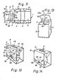
- the container is formed from a one-piece, tubular foldable blank 1, which essentially has parts 2, 3, 4 and 5.
- the part 2 forms the lid of the container, the parts 3 and 5 the side walls and the part 4 the bottom of the container created by the unfolded blank according to FIG. 7.
- the lid part 2 has an insertion opening formed by means of perforations 6, which is symmetrical is arranged to the longitudinal axis L of the blank.
- the lid part 2 also has at its edge a fold line 7, which delimits the lid part 2 from a closure strip 8, which is narrower than the lid part 2 and, as will be explained below, on its side facing the viewer in Fig. 7 with adhesive provided with the side wall part 5 is connectable so that a tubular blank is formed.
- the side wall parts 3, 5 have the same length as the cover part 2 and the bottom part 4.
- the parts 2-5 of the blank 1 Symmetrically on both sides of the longitudinal center line L of the blank 1, the parts 2-5 of the blank 1 have side flaps which are connected to the blank parts 2-5 by fold lines 9, 10, 11, 12.
- the side flaps 13 on each side of the cover part 2 have an approximately prismatic cross section and are delimited by the edges 14, 15, 16.
- the side tabs 17 of the side wall part 3 have an Ab cut 18, which is delimited by a fold line 19 from the central region 20 of the side flap 17.
- Another fold line 21 delimits this central area 20 from another section 22.
- the central region 20 of the side plate 17 has an acute-angled notch 23, the tip 24 of which is directed at an angle a of 45 ° against the longitudinal axis L of the blank.
- the blank 4 forming the bottom of the container has two side flaps 25 symmetrical to the longitudinal axis L of the blank. Between this flap and the side flap 77, a fold line 26 extends over a length 1, which fold line 26 continues or approximately experiences in the edge 27 of the side flap 25 .
- the side flap 25 has an approximately leaf-shaped section 28 which is connected to the central region 30 of the side flap 25 via a fold line 29 and is separated from the adjacent regions of the side flap 25 by curved incisions 31. Section 28 is of particular importance for the solution of the problem, and its function will be explained in more detail below.
- the fold line 29 also extends at an angle of approximately 45 ° to the longitudinal center line L of the blank 1.
- the side flap 32 is separated from the blank part 5 forming the second side wall of the container via the fold line 12.
- This flap has a section 33 which is separated from the central region 35 of the side flap 32 via a fold line 34 which is inclined at 135 ° relative to the longitudinal center line L.
- the longitudinal edge 36 of the side flap 32, before it merges into the fold line 34, has an acute-angled notch 37, which has a smaller cross section than the notch 23 of the side flap 17. This forms a support edge 23a, as does the notch 37, also in or approximately bearing edge 37a extending at right angles to the longitudinal central axis L.
- 1-4 shows the formation of the blank according to FIG. 5 with its sections lying one on top of the other.
- the sections 18 of the two side flaps 17 are folded outward or downward about the fold line 19 onto the central region 20 of the side flaps 17 (facing away from the viewer of FIG. 2).
- the leaf-shaped section 28 of the side flap 25 is placed around the fold line 29 on the central region of the side flap 25, so that the parts assume the position shown in FIG. 2, in which they are denoted by 18 'and 28'.
- the side flaps 13 placed on the cover part 2 of the blank are provided with an adhesive point 40.
- An adhesive point 41 is applied to the section 33 of the side flap 32 and the section 35a of the central region 35 of the side flap 32 adjacent to this point is given an adhesive point 42.
- the cover part 2 and the side wall part 5 are folded around the fold lines 43 and 44 onto the bottom part 4 and the second side wall part 3 and the closure strip 8 is glued to the outside of the side wall part 5 in the manner described above and the tubular cut is formed.
- the adhesive point 40 comes to lie on the section 18 'of the side flap 17 folded around the fold line 19 and connects these two parts to one another (cf. also FIG. 7), while the Adhesive point 42 comes to lie on the sheet-shaped section 28 ′ and this section is connected to the side tab 32.
- the adhesive point 41 at the corner 33a of the section 33 is glued to the tab-like section 25a of the side flap 25. It is particularly important to ensure that the adhesive site 41 is no larger than the tab-shaped section 25a.
- FIG. 9 shows the view of one of the end walls of the container from the inside of the container
- FIG. 10 shows the view from the outside
- the side flap 25 lies with its edge 27 and the fold line 26 on the through the Cut part 3 formed side wall of the container, as the folding line 26a and the edge 33a of the section 33 abuts against the part 5 forming the second side wall. Since the edges and lines mentioned limit a rectangular cross-section in their entirety, which corresponds to the inner cross-section of the container, this further reinforces the erected blank and container, which on the one hand increases the stability of the unfilled container, and on the other hand an additional securing of the container besides the Locking devices 23, 37 guaranteed.
- the length 1 of the fold lines 26, 26a determines the height of the container up to which the liquid tightness is given. Nevertheless, the sheet-shaped section 28 ensures the desired erection of the blank as in known containers (US Pat. No. 3,089,633 and DE-GM 85 26 754), in which the liquid tightness in the lower container area is not ensured.
- the parts 2 to 5 and the tabs and sections connected to them have the same configuration as in the embodiment according to FIGS. 1 to 10.
- the closure strip 8 is again provided, which is connected to the blank 5 is connected via the fold line 7.
- a flap 51 is connected to the closure strip 8 via a further fold line 50 which is parallel to the fold line 7 and which delimits the closure strip 8 between itself and the line 7.
- This flap has a further fold line 52, which has a slightly larger width than the strip 8, so that for the closure of the unfolded container, the section 53 between the fold lines 50, 52 can first be folded onto the part 5 or the closure strip 8, whereupon the flap section 51a between the line 52 and the flap edge 54, as indicated in FIG.
- the flap edge 54 has, as can be seen in FIGS. 11 and 12, a central tongue 55 which can be inserted into part 2 of a corresponding slot 56 on the folding line 44 by bending 90 ° along line 55c and there with its ends 55a , 55b is held clamped.
- the edge 54 of the flap 51 preferably has two tongues 57, 58 which correspond to two slots 59, 60 on the folded edge 44 of the blank.
- the central region of the flap section 51 a has a flap edge 61 starting from the flap edge 54, which on its three sides z. B.
- the tongue 55 is detachably connected to the part 5 by an adhesive point
- the part 63 is connected to the blank part 5 by an adhesive point 64. If such a blank is unfolded from the flat position of its parts (see FIG. 5) to form a container, then despite the stiffness of the blank and the container parts, these can be adjusted relative to one another in such a way that the blank parts can be easily unfolded against one another.
- the embodiment according to FIG. 14 serves the same purpose.
- three tongues 65, 66, 67 are provided on the edge 51a of the flap 51.
- the tongue 66 located in the middle is in turn connected to the flap 51 via two short webs 69, forming a slot 68, this middle tongue 66 being releasably glued to the blank 5, while the tongues 65, 67 like the tongues 57, 58 can remain without connection to part 5.
- the flap 51 After the flap 51 has been released from the part 5, the flap 51 can be folded in the direction of the arrow U in FIG. 12 onto the part 2 with the filling opening.
Landscapes
- Engineering & Computer Science (AREA)
- Mechanical Engineering (AREA)
- Cartons (AREA)
- Paper (AREA)
Claims (7)
Priority Applications (1)
| Application Number | Priority Date | Filing Date | Title |
|---|---|---|---|
| AT87112999T ATE52983T1 (de) | 1986-09-13 | 1987-09-05 | Sammelbehaelter aus karton fuer kleingegenstaende. |
Applications Claiming Priority (2)
| Application Number | Priority Date | Filing Date | Title |
|---|---|---|---|
| DE19863631268 DE3631268A1 (de) | 1986-09-13 | 1986-09-13 | Sammelbehaelter aus karton fuer kleingegenstaende |
| DE3631268 | 1986-09-13 |
Publications (2)
| Publication Number | Publication Date |
|---|---|
| EP0260554A1 EP0260554A1 (fr) | 1988-03-23 |
| EP0260554B1 true EP0260554B1 (fr) | 1990-05-23 |
Family
ID=6309570
Family Applications (1)
| Application Number | Title | Priority Date | Filing Date |
|---|---|---|---|
| EP87112999A Expired - Lifetime EP0260554B1 (fr) | 1986-09-13 | 1987-09-05 | Récipient en carton pour petits objets |
Country Status (3)
| Country | Link |
|---|---|
| EP (1) | EP0260554B1 (fr) |
| AT (1) | ATE52983T1 (fr) |
| DE (2) | DE3631268A1 (fr) |
Families Citing this family (3)
| Publication number | Priority date | Publication date | Assignee | Title |
|---|---|---|---|---|
| FR2873105B1 (fr) * | 2004-07-16 | 2007-12-14 | Sita Ile De France Sa | Boite en papier destinee a recevoir des papiers de bureau |
| DE102014017999B3 (de) * | 2014-12-04 | 2016-05-19 | Smurfit Kappa Gmbh | Karton mit Automatikboden |
| AT16941U1 (de) * | 2019-06-13 | 2020-12-15 | Amepro Gmbh | Kartonbehältersystem, Kartonbehälter und Kartonbehälterzuschnitt |
Family Cites Families (4)
| Publication number | Priority date | Publication date | Assignee | Title |
|---|---|---|---|---|
| US2677494A (en) * | 1950-10-11 | 1954-05-04 | Sutherland Paper Co | Collapsible automatic setup carton |
| US3057535A (en) * | 1960-04-04 | 1962-10-09 | Ferguson Lander Box Company | Carton |
| IT1085829B (it) * | 1976-07-10 | 1985-05-28 | Hammer Lit Gmbh | Recipiente di raccolta a perdere,di cartone o materia artificiale,per piccoli oggetti usati e per immondizie,specialmente per articoli medicinali |
| DE8526754U1 (de) * | 1985-09-19 | 1985-11-07 | Hammerlit Gmbh, 2950 Leer | Sammelbehälter aus Karton od. dgl. |
-
1986
- 1986-09-13 DE DE19863631268 patent/DE3631268A1/de not_active Withdrawn
-
1987
- 1987-09-05 EP EP87112999A patent/EP0260554B1/fr not_active Expired - Lifetime
- 1987-09-05 DE DE8787112999T patent/DE3762837D1/de not_active Expired - Fee Related
- 1987-09-05 AT AT87112999T patent/ATE52983T1/de active
Also Published As
| Publication number | Publication date |
|---|---|
| EP0260554A1 (fr) | 1988-03-23 |
| DE3631268A1 (de) | 1988-03-24 |
| DE3762837D1 (de) | 1990-06-28 |
| ATE52983T1 (de) | 1990-06-15 |
Similar Documents
| Publication | Publication Date | Title |
|---|---|---|
| DD146165A5 (de) | Kappenfaltschachtel | |
| EP0367945B1 (fr) | Emballage en carton | |
| DE29618895U1 (de) | Faltschachtel, insbesondere zur Aufbewahrung von Hygieneartikeln | |
| CH653635A5 (de) | Sechseckige schachtel. | |
| DE1486558A1 (de) | Prismatischer Faltbehaelter | |
| EP0260554B1 (fr) | Récipient en carton pour petits objets | |
| DE8809938U1 (de) | Faltschachtel für Kleinteile | |
| DE9314930U1 (de) | Verpackung zum Aufbewahren und gleichzeitigen Exponieren einer Flasche | |
| DE2720591C2 (de) | Sammelbehälter aus Karton oder dergleichen für Kleingegenstände | |
| EP0058640A1 (fr) | Découpe pour une boîte pliante | |
| EP0271056A2 (fr) | Porte-emballage en carton ou similaire réalisé à partir d'un flan unique | |
| DE3741283A1 (de) | Schachtel mit einem flach zusammenlegbaren grundkoerper | |
| DE3807443A1 (de) | Faltbehaelter | |
| DE2914882A1 (de) | Faltbehaelter | |
| DE3637965C2 (de) | Behälter zum Transport von Pflanzen | |
| EP0371298A1 (fr) | Emballage en carton | |
| DE9313241U1 (de) | Korb für Obst, Gemüse u.dgl. | |
| DE8624607U1 (de) | Sammelbehälter aus Karton für Kleingegenstände | |
| DE2113549A1 (de) | Zuschnitt zur Herstellung von Gefachteilungen | |
| DE3627440A1 (de) | Zigarettenschachtel mit aufklappbarem deckel sowie schnittmuster zur herstellung derselben | |
| DE102004063655B4 (de) | Zuschnitt aus Karton oder dergleichen mit zusammensteckbarem Boden | |
| EP0340319A1 (fr) | Boîte pliante | |
| DE19638308B4 (de) | Faltschachtel | |
| DE102008029217B4 (de) | Trayverpackung, insbesondere für schwere Produkte | |
| DE2332654C3 (de) | Aus einem Kartonzuschnitt gebildeter Entnahmekarton |
Legal Events
| Date | Code | Title | Description |
|---|---|---|---|
| PUAI | Public reference made under article 153(3) epc to a published international application that has entered the european phase |
Free format text: ORIGINAL CODE: 0009012 |
|
| AK | Designated contracting states |
Kind code of ref document: A1 Designated state(s): AT BE CH DE FR IT LI NL |
|
| 17P | Request for examination filed |
Effective date: 19880415 |
|
| 17Q | First examination report despatched |
Effective date: 19890530 |
|
| GRAA | (expected) grant |
Free format text: ORIGINAL CODE: 0009210 |
|
| AK | Designated contracting states |
Kind code of ref document: B1 Designated state(s): AT BE CH DE FR IT LI NL |
|
| REF | Corresponds to: |
Ref document number: 52983 Country of ref document: AT Date of ref document: 19900615 Kind code of ref document: T |
|
| REF | Corresponds to: |
Ref document number: 3762837 Country of ref document: DE Date of ref document: 19900628 |
|
| ITF | It: translation for a ep patent filed | ||
| ET | Fr: translation filed | ||
| PGFP | Annual fee paid to national office [announced via postgrant information from national office to epo] |
Ref country code: BE Payment date: 19900927 Year of fee payment: 4 |
|
| PGFP | Annual fee paid to national office [announced via postgrant information from national office to epo] |
Ref country code: FR Payment date: 19900928 Year of fee payment: 4 |
|
| PGFP | Annual fee paid to national office [announced via postgrant information from national office to epo] |
Ref country code: NL Payment date: 19900930 Year of fee payment: 4 |
|
| PLBE | No opposition filed within time limit |
Free format text: ORIGINAL CODE: 0009261 |
|
| STAA | Information on the status of an ep patent application or granted ep patent |
Free format text: STATUS: NO OPPOSITION FILED WITHIN TIME LIMIT |
|
| 26N | No opposition filed | ||
| ITTA | It: last paid annual fee | ||
| PG25 | Lapsed in a contracting state [announced via postgrant information from national office to epo] |
Ref country code: BE Effective date: 19910930 |
|
| BERE | Be: lapsed |
Owner name: FIRMA HAMMERLIT G.M.B.H. Effective date: 19910930 |
|
| PG25 | Lapsed in a contracting state [announced via postgrant information from national office to epo] |
Ref country code: NL Effective date: 19920401 |
|
| NLV4 | Nl: lapsed or anulled due to non-payment of the annual fee | ||
| PG25 | Lapsed in a contracting state [announced via postgrant information from national office to epo] |
Ref country code: FR Effective date: 19920529 |
|
| REG | Reference to a national code |
Ref country code: FR Ref legal event code: ST |
|
| PGFP | Annual fee paid to national office [announced via postgrant information from national office to epo] |
Ref country code: CH Payment date: 19930902 Year of fee payment: 7 |
|
| PGFP | Annual fee paid to national office [announced via postgrant information from national office to epo] |
Ref country code: AT Payment date: 19930914 Year of fee payment: 7 |
|
| PG25 | Lapsed in a contracting state [announced via postgrant information from national office to epo] |
Ref country code: AT Effective date: 19940905 |
|
| PG25 | Lapsed in a contracting state [announced via postgrant information from national office to epo] |
Ref country code: LI Effective date: 19940930 Ref country code: CH Effective date: 19940930 |
|
| REG | Reference to a national code |
Ref country code: CH Ref legal event code: PL |
|
| PGFP | Annual fee paid to national office [announced via postgrant information from national office to epo] |
Ref country code: DE Payment date: 20030818 Year of fee payment: 17 |
|
| PG25 | Lapsed in a contracting state [announced via postgrant information from national office to epo] |
Ref country code: DE Free format text: LAPSE BECAUSE OF NON-PAYMENT OF DUE FEES Effective date: 20050401 |
|
| PG25 | Lapsed in a contracting state [announced via postgrant information from national office to epo] |
Ref country code: IT Free format text: LAPSE BECAUSE OF NON-PAYMENT OF DUE FEES Effective date: 20050905 |