EP0258570B1 - Dispositif pour déplacer un chariot ou similaire dans une direction avec une vitesse essentiellement constante, et son retour avec une vitesse inégale - Google Patents
Dispositif pour déplacer un chariot ou similaire dans une direction avec une vitesse essentiellement constante, et son retour avec une vitesse inégale Download PDFInfo
- Publication number
- EP0258570B1 EP0258570B1 EP87109624A EP87109624A EP0258570B1 EP 0258570 B1 EP0258570 B1 EP 0258570B1 EP 87109624 A EP87109624 A EP 87109624A EP 87109624 A EP87109624 A EP 87109624A EP 0258570 B1 EP0258570 B1 EP 0258570B1
- Authority
- EP
- European Patent Office
- Prior art keywords
- roller
- carriage
- lever
- frame
- rollers
- Prior art date
- Legal status (The legal status is an assumption and is not a legal conclusion. Google has not performed a legal analysis and makes no representation as to the accuracy of the status listed.)
- Expired - Lifetime
Links
Images


Classifications
-
- B—PERFORMING OPERATIONS; TRANSPORTING
- B29—WORKING OF PLASTICS; WORKING OF SUBSTANCES IN A PLASTIC STATE IN GENERAL
- B29C—SHAPING OR JOINING OF PLASTICS; SHAPING OF MATERIAL IN A PLASTIC STATE, NOT OTHERWISE PROVIDED FOR; AFTER-TREATMENT OF THE SHAPED PRODUCTS, e.g. REPAIRING
- B29C66/00—General aspects of processes or apparatus for joining preformed parts
- B29C66/80—General aspects of machine operations or constructions and parts thereof
- B29C66/83—General aspects of machine operations or constructions and parts thereof characterised by the movement of the joining or pressing tools
- B29C66/834—General aspects of machine operations or constructions and parts thereof characterised by the movement of the joining or pressing tools moving with the parts to be joined
- B29C66/8351—Jaws mounted on rollers, cylinders, drums, bands, belts or chains; Flying jaws
- B29C66/83541—Jaws mounted on rollers, cylinders, drums, bands, belts or chains; Flying jaws flying jaws, e.g. jaws mounted on crank mechanisms or following a hand over hand movement
- B29C66/83543—Jaws mounted on rollers, cylinders, drums, bands, belts or chains; Flying jaws flying jaws, e.g. jaws mounted on crank mechanisms or following a hand over hand movement cooperating flying jaws
-
- B—PERFORMING OPERATIONS; TRANSPORTING
- B29—WORKING OF PLASTICS; WORKING OF SUBSTANCES IN A PLASTIC STATE IN GENERAL
- B29C—SHAPING OR JOINING OF PLASTICS; SHAPING OF MATERIAL IN A PLASTIC STATE, NOT OTHERWISE PROVIDED FOR; AFTER-TREATMENT OF THE SHAPED PRODUCTS, e.g. REPAIRING
- B29C65/00—Joining or sealing of preformed parts, e.g. welding of plastics materials; Apparatus therefor
- B29C65/02—Joining or sealing of preformed parts, e.g. welding of plastics materials; Apparatus therefor by heating, with or without pressure
- B29C65/18—Joining or sealing of preformed parts, e.g. welding of plastics materials; Apparatus therefor by heating, with or without pressure using heated tools
-
- B—PERFORMING OPERATIONS; TRANSPORTING
- B29—WORKING OF PLASTICS; WORKING OF SUBSTANCES IN A PLASTIC STATE IN GENERAL
- B29C—SHAPING OR JOINING OF PLASTICS; SHAPING OF MATERIAL IN A PLASTIC STATE, NOT OTHERWISE PROVIDED FOR; AFTER-TREATMENT OF THE SHAPED PRODUCTS, e.g. REPAIRING
- B29C66/00—General aspects of processes or apparatus for joining preformed parts
- B29C66/40—General aspects of joining substantially flat articles, e.g. plates, sheets or web-like materials; Making flat seams in tubular or hollow articles; Joining single elements to substantially flat surfaces
- B29C66/41—Joining substantially flat articles ; Making flat seams in tubular or hollow articles
- B29C66/43—Joining a relatively small portion of the surface of said articles
- B29C66/431—Joining the articles to themselves
- B29C66/4312—Joining the articles to themselves for making flat seams in tubular or hollow articles, e.g. transversal seams
-
- F—MECHANICAL ENGINEERING; LIGHTING; HEATING; WEAPONS; BLASTING
- F16—ENGINEERING ELEMENTS AND UNITS; GENERAL MEASURES FOR PRODUCING AND MAINTAINING EFFECTIVE FUNCTIONING OF MACHINES OR INSTALLATIONS; THERMAL INSULATION IN GENERAL
- F16H—GEARING
- F16H21/00—Gearings comprising primarily only links or levers, with or without slides
- F16H21/10—Gearings comprising primarily only links or levers, with or without slides all movement being in, or parallel to, a single plane
- F16H21/16—Gearings comprising primarily only links or levers, with or without slides all movement being in, or parallel to, a single plane for interconverting rotary motion and reciprocating motion
- F16H21/18—Crank gearings; Eccentric gearings
- F16H21/36—Crank gearings; Eccentric gearings without swinging connecting-rod, e.g. with epicyclic parallel motion, slot-and-crank motion
-
- B—PERFORMING OPERATIONS; TRANSPORTING
- B29—WORKING OF PLASTICS; WORKING OF SUBSTANCES IN A PLASTIC STATE IN GENERAL
- B29C—SHAPING OR JOINING OF PLASTICS; SHAPING OF MATERIAL IN A PLASTIC STATE, NOT OTHERWISE PROVIDED FOR; AFTER-TREATMENT OF THE SHAPED PRODUCTS, e.g. REPAIRING
- B29C66/00—General aspects of processes or apparatus for joining preformed parts
- B29C66/01—General aspects dealing with the joint area or with the area to be joined
- B29C66/05—Particular design of joint configurations
- B29C66/10—Particular design of joint configurations particular design of the joint cross-sections
- B29C66/11—Joint cross-sections comprising a single joint-segment, i.e. one of the parts to be joined comprising a single joint-segment in the joint cross-section
- B29C66/112—Single lapped joints
- B29C66/1122—Single lap to lap joints, i.e. overlap joints
Definitions
- the invention relates to a device for moving a carriage or the like in one direction at substantially the same speed and for returning it at a non-uniform speed, preferably for the intermittent preference of a film web relative to a welding device fixed to the frame or for the intermittent speed-equal advancement of a welding device relative to one moving film web, with a lever that can be swiveled back and forth by a drive, which, via a first link guide running in the longitudinal direction thereof, and a sliding block or a roller in a plane parallel to the pivoting plane of the lever Guides movable carriage gives the drive movement, the holder of the sliding block or the bearing of the roller are slidably guided on a line which is the basis of an isosceles triangle, the legs of which are defined by the lever pivoted into its end positions.
- the object of the invention is therefore to provide a device of the type specified at the outset, which has a more compact and thus space-saving design.
- the above-described first embodiment of the device according to the invention makes it possible to carry out processing on a device continuous web, in particular tubular film web, to be provided, for example, for the production of sacks with transverse weld seams or also with punched-outs.
- a device continuous web in particular tubular film web
- the device according to the invention for webs, preferably tubular webs, from which sections, for example bags provided with bottom and / or top seams, are separated and conveyed individually, in shingles one above the other or in stack form.
- a device for the intermittent preference of a film web fed at a constant speed relative to a cross-cut or cross-cut welding device fixed to the frame that rollers or rollers are mounted in the end regions of the slide transversely to its direction of displacement, via which an endless belt or an endless belt runs, the upper run wraps around loop-fixed deflection rollers or rollers and the lower run in loop form runs over feed rollers for the film web, and that the film web runs from the feed rollers over the rear roller of the carriage in the film feed direction and the first from the top run of the belt or Belt intermittently driven frame-fixed deflection roller runs.
- the rollers or rollers mounted in the carriage and the frame-fixed rollers or rollers are driven or coupled by the endless belt that wraps around them, so that they are in drive connection with the preferred rollers for the incoming film web without all rollers and / or rollers of the Foil sheet itself are wrapped.
- the film web which in this embodiment only runs over the rear roller of the carriage in the film feed direction and the first frame-fixed deflection roller driven intermittently by the upper run of the belt or belt, can therefore pass behind this deflection roller continued in any form or separated and stored in sections.
- the first deflection roller fixed to the frame and driven intermittently by the upper run of the belt or belt is expediently a roller of a second pair of preferred rollers for the film web.
- a depositing table or a depositing conveyor belt can be provided behind this roller or this second pair of preferred rollers, a cross-welding separating or cross-cutting device which separates sections or bags from the web or tubular film web can be arranged between the two.
- crank pin is fastened in a holder which is mounted on a radial guide of the Crank is longitudinally displaceable to this and that the holder is provided on its side opposite the crank pin with a pin which carries a sliding block or a roller which runs in a closed frame-fixed curve guide enclosing the crank shaft pin with the desired characteristic.
- the guides of the slide run parallel to the base of the isosceles triangle and that the slide is provided with a guide perpendicular to these guides, in which the carrier of the in the first guide of the lever-guided roller is guided adjustable by adjusting means.
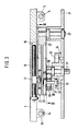
- a supply roll 1 is mounted in a stand, from which a film tube web 2, for example to be processed into bags or sacks, is continuously drawn off by the feed rollers 3.
- the film tube web 2 runs over a frame-fixed deflection roller 4 to two rollers 6 and 7 mounted at a distance from one another in a carriage 5.
- a frame-fixed sealing device 8 of a conventional type is provided.
- the film tubular web provided with sealing seams then runs over a deflection roller 9 fixed to the frame and a feed roller 10 to a buffer store consisting of a pendulum roller 11 and from there to the winding device 12, by means of which the tubular film web provided with weld seams is wound up into a supply roll.
- the carriage 5 is provided with guide brackets 13 which grip guide rods 14 fixed to the frame and are guided thereon.
- the two guide rods 14 are firmly connected to the machine frame 15 in the region of their ends, so that the slide 5 can be pushed back and forth on the guide rods 14 in the direction of arrow A.
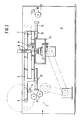
- it has a guide groove 16 in which an adjusting nut 17 is guided, which can be moved in the groove 16 via a threaded spindle rod in the groove 16 for the purpose of format adjustment.
- a pin 19 is fixedly connected to the adjusting nut 17 and carries a guide roller 20 at its end facing away from the adjusting nut 17.
- This guide roller 20 is guided in a guide track 21 which is provided in the rocker 22 consisting of a lever.
- the rocker 22 is pivotally mounted about the axis 23 in the gear housing 24, which is connected to the frame.
- the rocker 22 is next to the Guide track 21 provided with a second guide track 25 running parallel to this.
- a roller 26 is guided, which is placed on one end of the crank pin 27.
- the crank pin 27 is held by a sliding block 28 which is slidably mounted in the crank arm 30 on guide rods 29.
- the crank arm 30 is fastened on the crankshaft journal 31.
- the amount of displacement of the sliding block 28 on the guide rods 29 with each revolution of the crankshaft pin 31 is determined by the configuration of the cam groove 32, in which a roller 33 is guided, which is placed on the end of the crank pin 27 opposite the roller 26.
- the cam groove 32 is machined into the hub 34, which is firmly connected to the housing 24.
- the configuration of the guide groove 32 ensures that, in the manner shown in the diagrams according to FIGS. 7 and 8, a constant speed is achieved over a certain path, so that the deflection rollers 6, 7 of the carriage 5 during the sealing time with such a speed Speed are shifted so that there is no relative movement between the continuously drawn hose or half-hose web 2 and the sealing device 8.
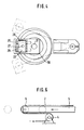
- the intermittent standstill of the tubular film web 2 during the sealing times is achieved by correspondingly moving the slide 5, the end position of the slide being shown in FIG. 6 by the rollers 6 shown in broken lines.
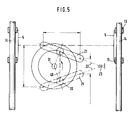
- Fig. 5 the slide 5 is shown schematically on the guide rods 14. Furthermore, the rocker arm 22, which can be pivoted about the axis 23, has dash-dotted lines and the guide groove 21 provided on its upper side has been hinted at.
- the roller 20 is guided in the guide groove 21. Since the roller 20 is adjustable via its holder 17 in the groove 16 of the slide 15, the slide stroke can be adjusted from the maximum stroke length shown to the indicated minimum stroke length by the adjustment. Since the roller 20 is held in its respective setting relative to the slide, it is guided on lines parallel to the guides 14, of which a line 40 is indicated by dashed lines in FIG. 5. As can be seen from FIG. 5, line 40 is the basis of an isosceles triangle, the legs of which are defined by the rocker arm 22 pivoted into its end positions.
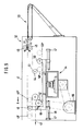
- FIG. 9 shows a device in which bags provided with bottom weld seams from the tubular film web 42 are welded and placed on a stacking belt.
- the device has two side frames, of which only the rear side frame 41 is shown for the sake of clarity.
- a pair of preferred rollers 42 is mounted, via which the tubular web 43 is continuously advanced.
- a deflection roller 44 and a pair of preferred rollers 45 are mounted in the side frame 41.
- two parallel guide rods 45 are provided, which are connected via crossbars 47 to the side frame (not shown) and to the side frame 41.
- a slide 48 which carries two deflection rollers 49 and 50, is slidably placed on the guide rods 46.
- the carriage 48 is traced in the manner described with reference to FIGS. 1 to 8. From the drawing it can be seen that the pair of preferred rollers 42, the deflecting roller 49, the lower deflecting roller of the pair of rollers 45, the deflecting roller 44 and the deflecting roller 50 are wrapped in an endless belt 51.
- the hose web 43 continuously advanced by the pair of preferred rollers 42 only wraps around the deflection roller 49. It then follows then discontinuously advanced by the pair of preferred rollers 45.
- Via a device known per se, designated by 52, 45 individual hose sections are then separated from the web 43 and provided, for example, with a bottom seam, in time with the pair of preferred rollers. The individual separated hose sections can then, for example, be placed on a scale-forming conveyor belt 53.
Landscapes
- Engineering & Computer Science (AREA)
- Mechanical Engineering (AREA)
- General Engineering & Computer Science (AREA)
- Making Paper Articles (AREA)
- Containers And Plastic Fillers For Packaging (AREA)
- Lining Or Joining Of Plastics Or The Like (AREA)
- Transmission Devices (AREA)
Claims (6)
- Dispositif pour déplacer un chariot (5) ou similaire dans une direction avec une vitesse essentiellement constante, et pour son retour avec une vitesse inégale, de préférence pour la traction intermittente d'une bande en feuille amenée à vitesse constante par rapport à un dispositif de soudage solidaire du bâti ou pour l'avance cadencée à la même vitesse d'un dispositif de soudage par rapport à une bande en feuille en déplacement,
comprenant un levier (22) pouvant être pivoté suivant un mouvement alternatif par l'intermédiaire d'un entraînement, levier qui, par l'intermédiaire d'un premier guide de coulisse (21) s'étendant dans celui-ci dans la direction longitudinale de celui-ci et un premier coulisseau ou un premier rouleau (20) communique le mouvement d'entraînement au chariot (5) pouvant être déplacé dans des guidages dans un plan parallèle au plan de pivotement du levier,
le dispositif de fixation ou de maintien du premier coulisseau ou le palier du premier rouleau étant guidé de façon déplaçable sur une ligne qui constitue la base d'un triangle à ailes égales dont les ailes sont définies par le levier (22) pivoté dans ses positions extrêmes,
caractérisé
en ce que l'entraînement du levier (22) est constitué par une manivelle (30) tournant dans un plan parallèle au plan de pivotement du levier (22) comprenant un tourillon du vilebrequin entraîné (31) dont le tourillon de manivelle (27) supporte un deuxième coulisseau ou un deuxième rouleau (26) qui se déplace dans un deuxième guide de coulisse (25) du levier (22) qui se trouve sur son côté opposé au premier guide de coulisse (21), et en ce que le tourillon de manivelle (27) est fixé dans un dispositif de fixation (28) qui est guidé sur un guidage radial (29) de la manivelle (30) de façon déplaçable longitudinalement par rapport à celle-ci, et en ce que le dispositif de fixation ou de maintien (28) sur son côté opposé au tourillon de manivelle est pourvu d'un tourillon qui supporte un troisième coulisseau ou un troisième rouleau (33) qui se déplace dans un guidage de courbe (32) solidaire du bâti, fermé, entourant le tourillon du vilebrequin (31), suivant la caractéristique recherchée. - Dispositif selon la revendication 1, caractérisé en ce que dans les zones extrêmes du chariot (48), transversalement à sa direction de déplacement sont placés des cylindres (49, 50) ou des rouleaux sur lesquels passe une bande sans fin (51) ou une courroie sans fin dont le brin supérieur entoure à la manière d'une boucle des cylindres ou rouleaux de déviation (45, 44) solidaires du bâti, et dont le brin inférieur passe sous forme de boucle sur des cylindres de traction (42) de la bande en feuille (43), et en ce que la bande en feuille (43) passe des cylindres de traction (42) sur le cylindre (49) arrière dans la direction d'amenée de la feuille du chariot (48) et le premier cylindre de déviation (45) solidaire du bâti, entraîné par intermittence, par le brin supérieur de la bande (51) ou de la courroie.
- Dispositif selon la revendication 1 ou 2, caractérisé en ce que le cylindre de déviation (45) solidaire du bâti entraîné par intermittence par le brin supérieur de la bande (51) ou de la courroie est un cylindre d'une deuxième paire de cylindres de traction de la bande en feuille (43).
- Dispositif selon la revendication 1 ou 2, caractérisé en ce qu'il est prévu derrière le premier cylindre de déviation (45) solidaire du bâti entraîné par intermittence par le brin supérieur de la bande (51) ou la courroie une table de réception ou une bande transporteuse de réception (53), et qu'il est prévu, entre les deux, un dispositif de séparation de coupe transversale ou de soudure transversale (52).
- Dispositif selon l'une des revendications 1 à 4, caractérisé en ce que les tourillons fixés au dispositif de fixation ou de maintien (28) sont alignés les uns avec les autres.
- Dispositif selon l'une des revendications 1 à 5, caractérisé en ce que les guidages (14) du chariot (5) s'étendent de façon parallèle à la base (40) du triangle à ailes égales (22, 40), et en ce que le chariot (5) est pourvu d'un guidage (16) à angle droit par rapport à ces guidages (13) dans lequel est guidé de façon déplaçable par des moyens de réglage (18) le support (17) du rouleau (20) guidé dans le premier guide de coulisse (21) du levier (22).
Applications Claiming Priority (4)
| Application Number | Priority Date | Filing Date | Title |
|---|---|---|---|
| DE3623699 | 1986-07-14 | ||
| DE3623699A DE3623699C1 (en) | 1986-07-14 | 1986-07-14 | Device for moving a carriage or the like in one direction with an essentially uniform velocity and for moving it back with non-uniform velocity |
| DE3711653 | 1987-04-07 | ||
| DE19873711653 DE3711653A1 (de) | 1987-04-07 | 1987-04-07 | Vorrichtung zum verfahren eines schlittens o. dgl. in einer richtung mit im wesentlichen gleicher geschwindigkeit und zu dessen zurueckfuehren mit ungleichfoermiger geschwindigkeit |
Publications (3)
| Publication Number | Publication Date |
|---|---|
| EP0258570A2 EP0258570A2 (fr) | 1988-03-09 |
| EP0258570A3 EP0258570A3 (en) | 1990-05-02 |
| EP0258570B1 true EP0258570B1 (fr) | 1992-09-30 |
Family
ID=25845557
Family Applications (1)
| Application Number | Title | Priority Date | Filing Date |
|---|---|---|---|
| EP87109624A Expired - Lifetime EP0258570B1 (fr) | 1986-07-14 | 1987-07-03 | Dispositif pour déplacer un chariot ou similaire dans une direction avec une vitesse essentiellement constante, et son retour avec une vitesse inégale |
Country Status (5)
| Country | Link |
|---|---|
| US (1) | US4811879A (fr) |
| EP (1) | EP0258570B1 (fr) |
| CA (1) | CA1292022C (fr) |
| DK (1) | DK162749C (fr) |
| ES (1) | ES2034995T3 (fr) |
Families Citing this family (1)
| Publication number | Priority date | Publication date | Assignee | Title |
|---|---|---|---|---|
| US6890796B1 (en) | 1997-07-16 | 2005-05-10 | Oki Electric Industry Co., Ltd. | Method of manufacturing a semiconductor package having semiconductor decice mounted thereon and elongate opening through which electodes and patterns are connected |
Citations (1)
| Publication number | Priority date | Publication date | Assignee | Title |
|---|---|---|---|---|
| US3053129A (en) * | 1958-10-13 | 1962-09-11 | Commercial Envelope Mfg Co Inc | High speed means for feeding a strip with constant speed input but with intermittent motion at the work location |
Family Cites Families (12)
| Publication number | Priority date | Publication date | Assignee | Title |
|---|---|---|---|---|
| US1883025A (en) * | 1929-10-14 | 1932-10-18 | American Brake Materials Corp | Machine for cutting friction elements |
| DE931629C (de) * | 1951-05-22 | 1955-08-11 | Windmoeller & Hoelscher | Maschine zum Herstellen heissverklebter Flachbeutel |
| DE1147379B (de) * | 1960-11-16 | 1963-04-18 | Windmoeller & Hoelscher | Vorrichtung zum Herstellen von Flachbeuteln aus thermoplastischen Kunststoffbahnen |
| DE1303722C2 (de) * | 1963-01-14 | 1973-11-22 | Synchronisiereinrichtung fuer den spannungsrichtigen abzug einer materialbahn | |
| US3883389A (en) * | 1971-07-06 | 1975-05-13 | Gloucester Eng Co Inc | Continuous reciprocating web drive means working with intermittent heat seal forming means |
| US3863823A (en) * | 1973-09-04 | 1975-02-04 | Allred Metal Stamping Works | Strip Stock Feeding Mechanism |
| US3953129A (en) * | 1975-01-09 | 1976-04-27 | The Unites States Of America As Represented By The Secretary Of The Army | Testing and inspecting lens by holographic means |
| IL48233A (en) * | 1975-10-03 | 1980-10-26 | Zlaikha Eliyahu | Automatic strip-feeder device particularly for punch dies |
| FR2380086A1 (fr) * | 1977-02-15 | 1978-09-08 | Bihler Otto | Dispositif d'avancement pour l'introduction d'une matiere, notamment en bande ou fil continus, dans une machine ou un dispositif |
| JPS5933486B2 (ja) * | 1980-12-20 | 1984-08-16 | 株式会社明電舎 | せん断機 |
| DE3234227C2 (de) * | 1981-12-01 | 1985-05-09 | Windmöller & Hölscher, 4540 Lengerich | Vorrichtung zum Anbringen von Querschweißnähten oder Querschweißtrennähten an kontinuierlich geförderten schlauch- oder halbschlauchförmigen Folienbahnen |
| DE3247001A1 (de) * | 1982-12-18 | 1984-06-20 | RWM-Raster-Werkzeugmaschinen GmbH, 7136 Ötisheim | Zangenvorschubeinrichtung fuer band- oder drahtmaterial |
-
1987
- 1987-06-16 CA CA000539832A patent/CA1292022C/fr not_active Expired - Fee Related
- 1987-07-03 ES ES198787109624T patent/ES2034995T3/es not_active Expired - Lifetime
- 1987-07-03 EP EP87109624A patent/EP0258570B1/fr not_active Expired - Lifetime
- 1987-07-13 DK DK364687A patent/DK162749C/da not_active IP Right Cessation
- 1987-07-14 US US07/073,129 patent/US4811879A/en not_active Expired - Fee Related
Patent Citations (1)
| Publication number | Priority date | Publication date | Assignee | Title |
|---|---|---|---|---|
| US3053129A (en) * | 1958-10-13 | 1962-09-11 | Commercial Envelope Mfg Co Inc | High speed means for feeding a strip with constant speed input but with intermittent motion at the work location |
Also Published As
| Publication number | Publication date |
|---|---|
| DK162749B (da) | 1991-12-09 |
| CA1292022C (fr) | 1991-11-12 |
| EP0258570A2 (fr) | 1988-03-09 |
| DK162749C (da) | 1992-04-27 |
| US4811879A (en) | 1989-03-14 |
| DK364687A (da) | 1988-01-15 |
| ES2034995T3 (es) | 1993-04-16 |
| EP0258570A3 (en) | 1990-05-02 |
| DK364687D0 (da) | 1987-07-13 |
Similar Documents
| Publication | Publication Date | Title |
|---|---|---|
| DE2402545C2 (de) | Verfahren und Vorrichtung zum kontinuierlichen Herstellen von Beuteln o.dgl. aus thermoplastischer Kunststoffolie | |
| DE2825722C2 (de) | Vorrichtung zum Herstellen von Beuteln oder Säcken und zu deren Ablegen in Schuppenformation | |
| DE2735396A1 (de) | Form-, abfuell- und schweissmaschine fuer verpackungen | |
| DE3941184A1 (de) | Vorrichtung zur trennung eines kontinuierlich gefoerderten stroms von geschuppt uebereinander liegenden flachen werkstuecken | |
| EP0111210B1 (fr) | Dispositif d'enveloppement d'articles avec une feuille en matière plastique ou similaire | |
| DE2524487C3 (de) | Vorrichtung zum Herstellen und Bündeln von Etiketten | |
| DE3340279C2 (de) | Vorrichtung zum Anspleißen des nachlaufenden Endes einer ersten Kunststoffolie an das vorlaufende Ende einer zweiten Kunststoffolie | |
| EP0258570B1 (fr) | Dispositif pour déplacer un chariot ou similaire dans une direction avec une vitesse essentiellement constante, et son retour avec une vitesse inégale | |
| DE2037670B2 (de) | Verfahren zur herstellung von beuteln aus einer folienbahn, insbesondere aus einer kunststoffolie oder einer kunststoffbeschichteten papier-, zellophanoder aluminiumfolie und vorrichtung zu seiner durchfuehrung | |
| DE3838563A1 (de) | Vorrichtung zum stapeln von flachen gegenstaenden | |
| EP0014858B1 (fr) | Procédé et dispositif pour appliquer des rubans d'ouverture ou analogues sur une feuille de matériau d'empaquetage | |
| DE2431790C2 (de) | Vorrichtung zum Kehlnahtschweißen von Längsgliedern an einer waagerechten Grundplatte einer Rahmenkonstruktion | |
| DE3711653C2 (fr) | ||
| DE2354974A1 (de) | Verfahren und vorrichtung zum stapeln und ablegen von beuteln | |
| EP0802137A2 (fr) | Dispositif pour le retournement et l'alimentation de paquets | |
| EP0461461B1 (fr) | Dispositif pour emballer une pile d'objets avec une housse étirable | |
| DE3623699C1 (en) | Device for moving a carriage or the like in one direction with an essentially uniform velocity and for moving it back with non-uniform velocity | |
| DE3045049C2 (de) | Packstück-Umschnürungsmaschine mit Ausrichtstation | |
| DE1900768B2 (de) | Vorrichtung zum befestigen von abreisstreifen | |
| DE2039024B1 (de) | Stofflege- und Schneidemaschine | |
| DE2163926C3 (de) | Einrichtung zur Herstellung von weichen Beuteln oder Taschen | |
| DE2249367C3 (de) | Vorrichtung zum kontinuierlichen Aufwickeln dünnen bahnförmigen Guts | |
| DE2833233C2 (de) | Verfahren und Vorrichtung zum Abtrennen von für die Herstellung von Säcken bestimmten Schlauchabschnitten von Schlauchbahnen und zu deren Transport zu Bodenlegemaschinen | |
| DE2858022C2 (de) | Vorrichtung zum Abziehen eines Stapels von Beuteln aus Kunststoffolien unter einem sich bildenden Stapel | |
| DE2343854C2 (de) | Vorrichtung zum Wenden von Schlauchabschnittpaketen |
Legal Events
| Date | Code | Title | Description |
|---|---|---|---|
| PUAI | Public reference made under article 153(3) epc to a published international application that has entered the european phase |
Free format text: ORIGINAL CODE: 0009012 |
|
| AK | Designated contracting states |
Kind code of ref document: A2 Designated state(s): BE ES FR GB IT SE |
|
| PUAL | Search report despatched |
Free format text: ORIGINAL CODE: 0009013 |
|
| AK | Designated contracting states |
Kind code of ref document: A3 Designated state(s): BE ES FR GB IT SE |
|
| 17P | Request for examination filed |
Effective date: 19900523 |
|
| 17Q | First examination report despatched |
Effective date: 19910415 |
|
| GRAA | (expected) grant |
Free format text: ORIGINAL CODE: 0009210 |
|
| AK | Designated contracting states |
Kind code of ref document: B1 Designated state(s): BE ES FR GB IT SE |
|
| ITF | It: translation for a ep patent filed |
Owner name: BUGNION S.P.A. |
|
| GBT | Gb: translation of ep patent filed (gb section 77(6)(a)/1977) | ||
| ET | Fr: translation filed | ||
| REG | Reference to a national code |
Ref country code: ES Ref legal event code: FG2A Ref document number: 2034995 Country of ref document: ES Kind code of ref document: T3 |
|
| PGFP | Annual fee paid to national office [announced via postgrant information from national office to epo] |
Ref country code: GB Payment date: 19930625 Year of fee payment: 7 |
|
| PGFP | Annual fee paid to national office [announced via postgrant information from national office to epo] |
Ref country code: BE Payment date: 19930709 Year of fee payment: 7 |
|
| PGFP | Annual fee paid to national office [announced via postgrant information from national office to epo] |
Ref country code: SE Payment date: 19930713 Year of fee payment: 7 Ref country code: ES Payment date: 19930713 Year of fee payment: 7 |
|
| PGFP | Annual fee paid to national office [announced via postgrant information from national office to epo] |
Ref country code: FR Payment date: 19930721 Year of fee payment: 7 |
|
| PLBE | No opposition filed within time limit |
Free format text: ORIGINAL CODE: 0009261 |
|
| STAA | Information on the status of an ep patent application or granted ep patent |
Free format text: STATUS: NO OPPOSITION FILED WITHIN TIME LIMIT |
|
| 26N | No opposition filed | ||
| PG25 | Lapsed in a contracting state [announced via postgrant information from national office to epo] |
Ref country code: GB Effective date: 19940703 |
|
| PG25 | Lapsed in a contracting state [announced via postgrant information from national office to epo] |
Ref country code: SE Effective date: 19940704 Ref country code: ES Free format text: LAPSE BECAUSE OF THE APPLICANT RENOUNCES Effective date: 19940704 |
|
| PG25 | Lapsed in a contracting state [announced via postgrant information from national office to epo] |
Ref country code: BE Effective date: 19940731 |
|
| BERE | Be: lapsed |
Owner name: WINDMOLLER & HOLSCHER Effective date: 19940731 |
|
| EUG | Se: european patent has lapsed |
Ref document number: 87109624.4 Effective date: 19950210 |
|
| GBPC | Gb: european patent ceased through non-payment of renewal fee |
Effective date: 19940703 |
|
| PG25 | Lapsed in a contracting state [announced via postgrant information from national office to epo] |
Ref country code: FR Effective date: 19950331 |
|
| EUG | Se: european patent has lapsed |
Ref document number: 87109624.4 |
|
| REG | Reference to a national code |
Ref country code: FR Ref legal event code: ST |
|
| REG | Reference to a national code |
Ref country code: ES Ref legal event code: FD2A Effective date: 19991007 |
|
| PG25 | Lapsed in a contracting state [announced via postgrant information from national office to epo] |
Ref country code: IT Free format text: LAPSE BECAUSE OF NON-PAYMENT OF DUE FEES;WARNING: LAPSES OF ITALIAN PATENTS WITH EFFECTIVE DATE BEFORE 2007 MAY HAVE OCCURRED AT ANY TIME BEFORE 2007. THE CORRECT EFFECTIVE DATE MAY BE DIFFERENT FROM THE ONE RECORDED. Effective date: 20050703 |