EP0254873A2 - Schaltungsanordnung mit einer Brückenendstufe - Google Patents
Schaltungsanordnung mit einer Brückenendstufe Download PDFInfo
- Publication number
- EP0254873A2 EP0254873A2 EP87109104A EP87109104A EP0254873A2 EP 0254873 A2 EP0254873 A2 EP 0254873A2 EP 87109104 A EP87109104 A EP 87109104A EP 87109104 A EP87109104 A EP 87109104A EP 0254873 A2 EP0254873 A2 EP 0254873A2
- Authority
- EP
- European Patent Office
- Prior art keywords
- circuit arrangement
- switch
- arrangement according
- bridge
- output stage
- Prior art date
- Legal status (The legal status is an assumption and is not a legal conclusion. Google has not performed a legal analysis and makes no representation as to the accuracy of the status listed.)
- Granted
Links
Images
Classifications
-
- H—ELECTRICITY
- H03—ELECTRONIC CIRCUITRY
- H03F—AMPLIFIERS
- H03F3/00—Amplifiers with only discharge tubes or only semiconductor devices as amplifying elements
- H03F3/30—Single-ended push-pull [SEPP] amplifiers; Phase-splitters therefor
- H03F3/3081—Duplicated single-ended push-pull arrangements, i.e. bridge circuits
-
- H—ELECTRICITY
- H03—ELECTRONIC CIRCUITRY
- H03F—AMPLIFIERS
- H03F1/00—Details of amplifiers with only discharge tubes, only semiconductor devices or only unspecified devices as amplifying elements
- H03F1/52—Circuit arrangements for protecting such amplifiers
Definitions
- the invention relates to a circuit arrangement according to the type of the main claim.
- the circuit arrangement according to the invention with the characterizing features of the main claim has the advantage that an impermissibly high housing temperature despite a large maximum output power of the output stages is prevented, operation of the output stages being continued, albeit with a reduced output power.
- circuit arrangement according to the invention can be implemented with a few additional components.
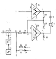
- the two push-pull amplifiers 1, 2 form a bridge output stage with A / B operation.
- the outputs 3, 4 of the push-pull amplifier 1, 2 form the output of the bridge output stage, to which a loudspeaker 6 or a loudspeaker group is connected via a bipolar capacitor 5.
- the push-pull amplifier 1, 2 can be constructed in a manner known per se as a complementary or quasi-complementary output stage. Since such circuits are well known, only the two end transistors 7, 8 and 9, 10 are indicated in the figure.
- the audio signal to be reproduced is fed to the push-pull amplifier 1 via a non-inverting input 11.
- the output signal of the push-pull amplifier 1 is fed to the inverting input of the push-pull amplifier 2 via a voltage divider 12, 13. With corresponding Tue Dimensioning of the voltage divider 12, 13 result at the outputs 3, 4 of the push-pull amplifier 1, 2 antiphase signals with the same amplitude.
- the in-phase signal can also be fed into the push-pull amplifier 2 in a manner known per se via negative-feedback networks of the push-pull amplifier 1, 2. Between the outputs 3, 4 there is therefore a signal with double amplitude, which is supplied to the loudspeaker 6 via the bipolar capacitor C.
- a temperature sensor 14 is in heat-conducting connection with a heat sink for the push-pull amplifiers 1, 2.
- An NTC or a PTC resistor, for example, through which a predetermined current flows, is suitable as the temperature sensor.
- the voltage drop across the temperature sensor is fed to a Schmitt trigger 15, the threshold values of which are set such that a switch 16 connected to the output of the Schmitt trigger 15 becomes conductive when the maximum permissible temperature is reached.
- the switch 16 connects the input 17 of the push-pull amplifier 2 via a diode 18 and a resistor 19 to the positive pole 25 of the operating voltage source.
- the transistor 10 in the push-pull amplifier 2 is controlled into the saturation state regardless of the size of the signal supplied via the resistor 12, 13.
- a diode 26 connected in parallel with the output 4 enables current to flow in the opposite direction.
- the output stage now works like a single output stage; the output signal supplied to the loudspeaker 6 now points more than half the amplitude, so that only a quarter of the power is delivered. This also reduces the power loss to a quarter with essentially the same efficiency.
- the entire arrangement, including the heat sink, is designed in such a way that cooling takes place below the maximum permissible temperature for a quarter of the total output. So that the power switching described does not take place too often, however, the switch 16 is only opened again at a temperature which is significantly below the maximum permissible temperature.
- the Schmitt trigger 15 is provided with a corresponding hysteresis.
- the output stages of several channels are usually provided with a common heat sink. It is therefore provided in the exemplary embodiment that the control circuit consisting of the thermal sensor 14, the Schmitt trigger 15 and the switch 16 controls the bridge output stages of a plurality of channels be connected. This can be, for example, a power amplifier with normal stereo reception. However, three additional channels can also be connected, for example, with a total of four-channel playback.
- the switch 16 is shown in the figure only by a switch symbol. However, a semiconductor switch, such as a transistor, is preferably suitable for this. So that no cracking noises occur when switching, the output voltage of the Schmitt trigger 15 of the control electrode can of the switch 16 are supplied via a low-pass filter, not shown, so that there is a gradual transition between the conductive and the non-conductive state of the switch 16.
Landscapes
- Engineering & Computer Science (AREA)
- Power Engineering (AREA)
- Amplifiers (AREA)
Abstract
Description
- Die Erfindung geht aus von einer Schaltungsanordnung nach der Gattung des Hauptanspruchs.
- Insbesondere bei Autoradios treten Probleme dadurch auf, daß bei gegebener Größe des Gerätes sowie maximal zulässige Gehäusetemperatur der Verlustleistung und damit auch der Ausgangsleistung Grenzen gesetzt sind. Neben Maßnahmen zur Verbesserung des Wirkungsgrades sind Schutzschaltungen bekannt geworden, die bei Erreichen einer vorgegebenen Temperatur den Signalfluß unterbrechen, um ihn nach dem Abkühlen wieder herzustellen. Diese bekannten Maßnahmen sind jedoch nicht besonders vorteilhaft, da der Benutzer eines Autoradios das Gerät während der Abkühlphase nicht benutzen kann.
- Die erfindungsgemäße Schaltungsanordnung mit den kennzeichnenden Merkmalen des Hauptanspruchs hat demgegenüber den Vorteil, daß eine unzulässig hohe Gehäusetemperatur trotz großer maximaler Ausgangs leistung der Endstufen verhindert wird, wobei ein Betrieb der Endstufen - wenn auch mit verminderter Ausgangsleistung - fortgesetzt wird.
- Besonders vorteilhaft ist ferner, daß sich die erfindungsgemäße Schaltungsanordnung mit wenigen zusätzlichen Bauelementen verwirklichen läßt.
- Durch die in den Unteransprüchen aufgeführten Maßnahmen sind vorteilhafte Weiterbildungen und Verbesserungen der im Hauptanspruch angegebenen Schaltungsanordnung möglich.
- Ein Ausführungsbeispiel der Erfindung ist in der Zeichnung schematisch dargestellt und in der nachfolgenden Beschreibung näher erläutert.
- Die beiden Gegentaktverstärker 1, 2 bilden eine Brückenendstufe mit A/B-Betrieb. Die Ausgänge 3, 4 der Gegentaktverstärker 1, 2 bilden den Ausgang der Brückenendstufe, an den uber einen bipolaren Kondensator 5 ein Lautsprecher 6 bzw. eine Lautsprechergruppe angeschlossen ist.
- Die Gegentaktverstärker 1, 2 können in an sich bekannter Weise als komplementäre oder quasi komplementäre Endstufe aufgebaut sein. Da derartige Schaltungen hinreichend bekannt sind, sind in der Figur lediglich jeweils die beiden Endtransistoren 7, 8 und 9, 10 angedeutet. Über einen nichtinvertierenden Eingang 11 wird das wiederzugebende Audiosignal dem Gegentaktverstärker 1 zugeführt. Das Ausgangssignal des Gegentaktverstärkers 1 wird über einen Spannungsteiler 12, 13 dem invertierenden Eingang des Gegentaktverstärkers 2 zugeführt. Bei entsprechender Di mensionierung des Spannungsteilers 12, 13 ergeben sich an den Ausgängen 3, 4 der Gegentaktverstärker 1, 2 gegenphasige Signale mit gleicher Amplitude. Eine Einspeisung des phasenrichtigen Signals in den Gegentaktverstärker 2 kann auch in an sich bekannter Weise über Gegenkopplungsnetzwerke der Gegentaktverstärker 1, 2 erfolgen. Zwischen den Ausgàngen 3, 4 liegt also ein Signal mit doppelter Amplitude, das über den bipolaren Kondensator C dem Lautsprecher 6 zugeführt wird.
- Ein Temperatursensor 14 steht in wärmeleitender Verbindung mit einem Kühlkörper für die Gegentaktverstärker 1, 2. Als Temperatursensor eignet sich beispielsweise ein NTC- oder ein PTC-Widerstand, der von einem vorgegebenen Strom durchflossen wird. Der Spannungsabfall an dem Temperatursensor wird einem Schmitt-Trigger 15 zugeführt, dessen Schwellwerte derart eingestellt sind, daß bei Erreichen der höchst zulässigen Temperatur ein an den Ausgang des Schmitt-Triggers 15 angeschlossener Schalter 16 leitend wird. Der Schalter 16 verbindet den Eingang 17 des Gegentaktverstärkers 2 über eine Diode 18 und einen Widerstand 19 mit dem positiven Pol 25 der Betriebsspannungsquelle. Dadurch wird der Transistor 10 im Gegentaktverstärker 2 unabhängig von der Größe des über den Widerstand 12, 13 zugeführten Signals in den Sättigungszustand gesteuert. Eine dem Ausgang 4 parallelgeschaltete Diode 26 ermöglicht einen Stromfluß in entgegengesetzter Richtung.
- Durch die damit bewirkte Verbindung des Ausgangs 4 des Gegentaktverstärkers 2 mit Masse arbeitet die Endstufe jetzt wie eine Einfachendstufe; das dem Lautsprecher 6 zugeführte Ausgangssignal weist nun mehr die halbe Amplitude auf, so daß nur noch ein Viertel der Leistung abgegeben wird. Damit wird auch die Verlustleistung bei im wesentlichen gleichen Wirkungsgrad auf ein Viertel reduziert.
- Die gesamte Anordnung einschließlich des Kühlkörpers ist derart ausgelegt, daß bei einem Viertel der Gesamtleistung eine Abkuhlung unter die höchst zulässige Temperatur erfolgt. Damit die beschriebene Leistungsumschaltung nicht zu oft erfolgt, wird jedoch der Schalter 16 erst wieder bei einer Temperatur geöffnet, die deutlich unter der höchst zulässigen Temperaturliegt. Hierzu ist der Schmitt-Trigger 15 mit einer entsprechenden Hysterese versehen.
- Üblicherweise sind die Endstufen mehrerer Kanäle mit einem gemeinsamen Kühlkörper versehen. Es ist daher bei dem Ausführungsbeispiel vorgesehen, daß die aus dem Thermosensor 14, dem Schmitt-Trigger 15 sowie dem Schalter 16 bestehende Steuerschaltung die Brückenendstufen mehrerer Kanäle steuert, dazu können an den Schaltungspunkt 20 uber Widerstände 21, 22 und Dioden 23, 24 weitere Brückenendstufen angeschlossen werden. Dieses kann beispielsweise eine Endstufe bei normalem Stereoempfang sein. Es können jedoch auch beispielsweise drei weitere Kanäle bei insgesamt vierkanaliger Wiedergabe angeschlossen werden.
- Der Schalter 16 ist in der Figur lediglich durch ein Schaltersymbol dargestellt. Es eignet sich jedoch vorzugsweise hierfür ein Halbleiterschalter, wie beispielsweise ein Transistor. Damit beim Umschalten keine Knackgeräusche auftreten, kann die Ausgangsspannung des Schmitt-Triggers 15 der Steuerelektrode des Schalters 16 über einen nicht dargestellten Tiefpaß zugeführt werden, so daß ein allmählicher Übergang zwischen dem leitenden und dem nichtleitenden Zustand des Schalters 16 erfolgt.
Claims (10)
daß in Abhängigkeit von der Temperatur der Endstufe einer der Brückenzweige (2) in einen Sättigungszustand steuerbar ist.
daß ein Temperatursensor (14) in wärmeleitender Verbindung mit der Endstufe (1, 2) steht,
daß das Ausgangssignal des Temperatursensors (14) über einen Schwellwertschalter (15) als Steuerspannung einem Schalter (16) zugeführt ist und
daß der Schalter (16) zwischen einem Pol (25) einer Betriebsspannungsquelle und dem Steuereingang (17) des Brückenzweiges (2) liegt.
daß der Schalter (16) ein elektronischer Schalter ist und die Steuerspannung über einen Tiefpaß zuge führt ist.
daß der Schwellwertschalter (15) ein Schmitt-Trigger ist.
daß zwischen dem Schalter (16) und dem Steuereingang (17) des Brückenzweiges (2) eine Diode (18) angeordnet ist, welche bei nichtleitendem Schalter (16) gesperrt ist.
, daß in Reihe mit der Diode (18) ein Widerstand (19) angeordnet ist.
daß dem anderen Brückenzweig (1) der Endstufe ein Audiosignal zuführbar ist und das Ausgangssignal des anderen Brückenzweiges (1) zur Steuerung des Brückenzweiges (2), welcher temperaturabhängig geschaltet wird, herangezogen wird.
daß der Temperatursensor (14) auf einem Kühlkörper für die Endstufe(n) angeordnet ist.
dadurch gekennzeichnet,
daß der Ausgang des Brückenzweiges (2) über eine Diode (26) mit einem Pol der Betriebsspannungsquelle verbunden ist, wobei die Diode (16) derart gepolt ist, daß sie beim Betrieb des Brückenzweiges (2) als Endstufe gesperrt ist.
Applications Claiming Priority (2)
| Application Number | Priority Date | Filing Date | Title |
|---|---|---|---|
| DE3622713 | 1986-07-05 | ||
| DE19863622713 DE3622713A1 (de) | 1986-07-05 | 1986-07-05 | Schaltungsanordnung mit einer brueckenendstufe |
Publications (3)
| Publication Number | Publication Date |
|---|---|
| EP0254873A2 true EP0254873A2 (de) | 1988-02-03 |
| EP0254873A3 EP0254873A3 (en) | 1989-03-15 |
| EP0254873B1 EP0254873B1 (de) | 1992-05-06 |
Family
ID=6304533
Family Applications (1)
| Application Number | Title | Priority Date | Filing Date |
|---|---|---|---|
| EP87109104A Expired - Lifetime EP0254873B1 (de) | 1986-07-05 | 1987-06-24 | Schaltungsanordnung mit einer Brückenendstufe |
Country Status (4)
| Country | Link |
|---|---|
| US (1) | US4792766A (de) |
| EP (1) | EP0254873B1 (de) |
| JP (1) | JPH06103805B2 (de) |
| DE (2) | DE3622713A1 (de) |
Cited By (2)
| Publication number | Priority date | Publication date | Assignee | Title |
|---|---|---|---|---|
| EP0425878A3 (en) * | 1989-10-31 | 1991-09-11 | Sgs-Thomson Microelectronics S.R.L. | High-efficiency audio amplifier |
| EP0658289B1 (de) * | 1992-09-04 | 1997-12-10 | Deutsche Thomson-Brandt Gmbh | Verfahren und vorrichtung zur ansteuerung mehrerer verbraucher |
Families Citing this family (7)
| Publication number | Priority date | Publication date | Assignee | Title |
|---|---|---|---|---|
| US5519886A (en) * | 1994-09-26 | 1996-05-21 | Motorola, Inc. | Method and apparatus for controlling device temperature during transmissions |
| DE19929429C2 (de) * | 1998-02-07 | 2003-10-30 | Ralph Mantel | Lautsprecherschutzschaltung |
| AU6035699A (en) * | 1998-09-14 | 2000-04-03 | Nokia Networks Oy | System and method for output power compensation for actual device temperature |
| KR100794050B1 (ko) * | 2006-12-13 | 2008-01-10 | 현대자동차주식회사 | 데크의 온도 유지 시스템 |
| JP5259270B2 (ja) | 2008-06-27 | 2013-08-07 | ルネサスエレクトロニクス株式会社 | 半導体装置 |
| US8330539B2 (en) * | 2009-08-14 | 2012-12-11 | Nxp B.V. | Dynamic switchable mode dual bridge power amplifier |
| US11188379B2 (en) * | 2018-09-21 | 2021-11-30 | International Business Machines Corporation | Thermal capacity optimization for maximized single core performance |
Family Cites Families (9)
| Publication number | Priority date | Publication date | Assignee | Title |
|---|---|---|---|---|
| US3277386A (en) * | 1963-10-21 | 1966-10-04 | Torio Company Ltd | Overload protection circuit for transistor amplifiers |
| JPS582607B2 (ja) * | 1976-03-12 | 1983-01-18 | パイオニア株式会社 | 温度検知回路 |
| US4053996A (en) * | 1976-03-24 | 1977-10-18 | General Motors Corporation | Power amplifier protection circuit |
| NL7902160A (nl) * | 1979-03-20 | 1980-09-23 | Philips Nv | Eindversterker met niet-lineaire tegenkoppeling. |
| JPS5921534Y2 (ja) * | 1979-05-17 | 1984-06-26 | ヤマハ株式会社 | Btlアンプ |
| FR2498844A1 (fr) * | 1981-01-27 | 1982-07-30 | Thomson Brandt | Dispositif de protection thermique d'un amplificateur de puissance en classe b, c, d ou ab et amplificateur comportant un tel dispositif |
| JPS6149616A (ja) * | 1984-08-10 | 1986-03-11 | シーメンス、アクチエンゲゼルシヤフト | 温度保護用回路装置 |
| US4611180A (en) * | 1985-01-09 | 1986-09-09 | Crown International, Inc. | Grounded bridge amplifier protection through transistor thermo protection |
| DE3517342A1 (de) * | 1985-05-14 | 1986-11-20 | Grundig E.M.V. Elektro-Mechanische Versuchsanstalt Max Grundig holländ. Stiftung & Co KG, 8510 Fürth | Leistungsverstaerker mit mehreren endstufen |
-
1986
- 1986-07-05 DE DE19863622713 patent/DE3622713A1/de active Granted
-
1987
- 1987-06-18 US US07/064,086 patent/US4792766A/en not_active Expired - Lifetime
- 1987-06-24 DE DE8787109104T patent/DE3778780D1/de not_active Expired - Fee Related
- 1987-06-24 EP EP87109104A patent/EP0254873B1/de not_active Expired - Lifetime
- 1987-07-06 JP JP62168514A patent/JPH06103805B2/ja not_active Expired - Fee Related
Cited By (2)
| Publication number | Priority date | Publication date | Assignee | Title |
|---|---|---|---|---|
| EP0425878A3 (en) * | 1989-10-31 | 1991-09-11 | Sgs-Thomson Microelectronics S.R.L. | High-efficiency audio amplifier |
| EP0658289B1 (de) * | 1992-09-04 | 1997-12-10 | Deutsche Thomson-Brandt Gmbh | Verfahren und vorrichtung zur ansteuerung mehrerer verbraucher |
Also Published As
| Publication number | Publication date |
|---|---|
| EP0254873B1 (de) | 1992-05-06 |
| DE3622713A1 (de) | 1988-01-07 |
| EP0254873A3 (en) | 1989-03-15 |
| DE3622713C2 (de) | 1991-03-14 |
| DE3778780D1 (de) | 1992-06-11 |
| JPH06103805B2 (ja) | 1994-12-14 |
| US4792766A (en) | 1988-12-20 |
| JPS6327105A (ja) | 1988-02-04 |
Similar Documents
| Publication | Publication Date | Title |
|---|---|---|
| DE3586863T2 (de) | Verstaerker mit eingangsfaehigkeit ueber den gesamten versorgungsspannungsbereich und geregelter transkonduktanz. | |
| EP0691735B1 (de) | Verstärkeranordnung und Empfängerschaltung, die die Verstärkeranordnung enthält | |
| EP1522142B1 (de) | Verstärkerschaltung mit einstellbarer verstärkung und sendeanordnung mit der verstärkerschaltung | |
| EP0254873B1 (de) | Schaltungsanordnung mit einer Brückenendstufe | |
| EP1189337B1 (de) | Gegentaktmischerschaltung unter Verwendung von bipolaren Transistoren | |
| EP0821476B1 (de) | Vorrichtung zur Offset-Kompensation einer Signalverarbeitungsschaltung | |
| EP0365085B1 (de) | Schaltungsanordnung zum Einstellen der Amplitude eines Signals | |
| DE2416534C3 (de) | Transistorschaltung zum Umkehren der Stromrichtung in einem Verbraucher | |
| EP1481487B1 (de) | Sendeanordnung | |
| DE1513409A1 (de) | Strombegrenzungsschaltung | |
| EP0908016B1 (de) | Schaltungsanordnung zur digitalen einstellung analoger parameter | |
| DE3210452A1 (de) | Signal-eingangsschaltung | |
| EP0004008B1 (de) | Schneller Amplitudenentscheider für digitale Signale | |
| EP0620648B1 (de) | ECL-CMOS-Pegelverschieber | |
| DE4106267A1 (de) | Autoradio | |
| EP1684422B1 (de) | Elektronisch schaltbare Eichleitung | |
| DE3341570A1 (de) | Endstufenanordnung | |
| DE3742796C2 (de) | ||
| EP0466233B1 (de) | Schaltungsanordnung zum wahlweisen Verstärken von Signalen | |
| DE69100502T2 (de) | Verstärker mit Doppelbandausgang. | |
| WO2025036670A1 (de) | Verstärkervorrichtung und hochfrequenzschaltkreis | |
| EP0548479A1 (de) | Verstärkerschaltung mit exponentieller Verstärkungssteuerung | |
| EP0806081B1 (de) | Schaltungsanordnung zum kurzzeitigen stummschalten der wiedergabe eines nf-signals in einem rundfunkempfänger | |
| DE2355512B2 (de) | Schaltungsanordnung zur wahlweisen anschaltung verschiedener signalquellen an den eingang eines verstaerkers | |
| DE2319824A1 (de) | Gegentaktverstaerkerschaltung |
Legal Events
| Date | Code | Title | Description |
|---|---|---|---|
| PUAI | Public reference made under article 153(3) epc to a published international application that has entered the european phase |
Free format text: ORIGINAL CODE: 0009012 |
|
| AK | Designated contracting states |
Kind code of ref document: A2 Designated state(s): DE FR GB IT SE |
|
| PUAL | Search report despatched |
Free format text: ORIGINAL CODE: 0009013 |
|
| AK | Designated contracting states |
Kind code of ref document: A3 Designated state(s): DE FR GB IT SE |
|
| 17P | Request for examination filed |
Effective date: 19890208 |
|
| 17Q | First examination report despatched |
Effective date: 19910430 |
|
| GRAA | (expected) grant |
Free format text: ORIGINAL CODE: 0009210 |
|
| AK | Designated contracting states |
Kind code of ref document: B1 Designated state(s): DE FR GB IT SE |
|
| REF | Corresponds to: |
Ref document number: 3778780 Country of ref document: DE Date of ref document: 19920611 |
|
| ET | Fr: translation filed | ||
| GBT | Gb: translation of ep patent filed (gb section 77(6)(a)/1977) | ||
| ITF | It: translation for a ep patent filed | ||
| PLBE | No opposition filed within time limit |
Free format text: ORIGINAL CODE: 0009261 |
|
| STAA | Information on the status of an ep patent application or granted ep patent |
Free format text: STATUS: NO OPPOSITION FILED WITHIN TIME LIMIT |
|
| 26N | No opposition filed | ||
| EAL | Se: european patent in force in sweden |
Ref document number: 87109104.7 |
|
| REG | Reference to a national code |
Ref country code: GB Ref legal event code: IF02 |
|
| PGFP | Annual fee paid to national office [announced via postgrant information from national office to epo] |
Ref country code: GB Payment date: 20020611 Year of fee payment: 16 |
|
| PGFP | Annual fee paid to national office [announced via postgrant information from national office to epo] |
Ref country code: FR Payment date: 20020622 Year of fee payment: 16 |
|
| PGFP | Annual fee paid to national office [announced via postgrant information from national office to epo] |
Ref country code: SE Payment date: 20020626 Year of fee payment: 16 |
|
| PGFP | Annual fee paid to national office [announced via postgrant information from national office to epo] |
Ref country code: DE Payment date: 20020802 Year of fee payment: 16 |
|
| PG25 | Lapsed in a contracting state [announced via postgrant information from national office to epo] |
Ref country code: GB Free format text: LAPSE BECAUSE OF NON-PAYMENT OF DUE FEES Effective date: 20030624 |
|
| PG25 | Lapsed in a contracting state [announced via postgrant information from national office to epo] |
Ref country code: SE Free format text: LAPSE BECAUSE OF NON-PAYMENT OF DUE FEES Effective date: 20030625 |
|
| PG25 | Lapsed in a contracting state [announced via postgrant information from national office to epo] |
Ref country code: DE Free format text: LAPSE BECAUSE OF NON-PAYMENT OF DUE FEES Effective date: 20040101 |
|
| EUG | Se: european patent has lapsed | ||
| GBPC | Gb: european patent ceased through non-payment of renewal fee |
Effective date: 20030624 |
|
| PG25 | Lapsed in a contracting state [announced via postgrant information from national office to epo] |
Ref country code: FR Free format text: LAPSE BECAUSE OF NON-PAYMENT OF DUE FEES Effective date: 20040227 |
|
| REG | Reference to a national code |
Ref country code: FR Ref legal event code: ST |
|
| PG25 | Lapsed in a contracting state [announced via postgrant information from national office to epo] |
Ref country code: IT Free format text: LAPSE BECAUSE OF NON-PAYMENT OF DUE FEES;WARNING: LAPSES OF ITALIAN PATENTS WITH EFFECTIVE DATE BEFORE 2007 MAY HAVE OCCURRED AT ANY TIME BEFORE 2007. THE CORRECT EFFECTIVE DATE MAY BE DIFFERENT FROM THE ONE RECORDED. Effective date: 20050624 |