EP0253383A2 - Aufhängungssystem vom Typ mit zwei Aufhängungsarmen - Google Patents
Aufhängungssystem vom Typ mit zwei Aufhängungsarmen Download PDFInfo
- Publication number
- EP0253383A2 EP0253383A2 EP87110242A EP87110242A EP0253383A2 EP 0253383 A2 EP0253383 A2 EP 0253383A2 EP 87110242 A EP87110242 A EP 87110242A EP 87110242 A EP87110242 A EP 87110242A EP 0253383 A2 EP0253383 A2 EP 0253383A2
- Authority
- EP
- European Patent Office
- Prior art keywords
- suspension system
- end section
- double link
- link type
- type suspension
- Prior art date
- Legal status (The legal status is an assumption and is not a legal conclusion. Google has not performed a legal analysis and makes no representation as to the accuracy of the status listed.)
- Granted
Links
- 239000000725 suspension Substances 0.000 title claims abstract description 70
- 230000035939 shock Effects 0.000 claims description 29
- 239000006096 absorbing agent Substances 0.000 claims description 26
- 238000009413 insulation Methods 0.000 description 27
- 238000006073 displacement reaction Methods 0.000 description 6
- 230000000694 effects Effects 0.000 description 4
- 230000002093 peripheral effect Effects 0.000 description 4
- 230000008602 contraction Effects 0.000 description 3
- 238000010521 absorption reaction Methods 0.000 description 2
- 230000005540 biological transmission Effects 0.000 description 2
- 239000004033 plastic Substances 0.000 description 2
- 230000002035 prolonged effect Effects 0.000 description 2
- 238000005096 rolling process Methods 0.000 description 2
- 229910000897 Babbitt (metal) Inorganic materials 0.000 description 1
- 239000000463 material Substances 0.000 description 1
Images


Classifications
-
- B—PERFORMING OPERATIONS; TRANSPORTING
- B62—LAND VEHICLES FOR TRAVELLING OTHERWISE THAN ON RAILS
- B62D—MOTOR VEHICLES; TRAILERS
- B62D17/00—Means on vehicles for adjusting camber, castor, or toe-in
-
- B—PERFORMING OPERATIONS; TRANSPORTING
- B60—VEHICLES IN GENERAL
- B60G—VEHICLE SUSPENSION ARRANGEMENTS
- B60G15/00—Resilient suspensions characterised by arrangement, location or type of combined spring and vibration damper, e.g. telescopic type
- B60G15/02—Resilient suspensions characterised by arrangement, location or type of combined spring and vibration damper, e.g. telescopic type having mechanical spring
- B60G15/06—Resilient suspensions characterised by arrangement, location or type of combined spring and vibration damper, e.g. telescopic type having mechanical spring and fluid damper
- B60G15/062—Resilient suspensions characterised by arrangement, location or type of combined spring and vibration damper, e.g. telescopic type having mechanical spring and fluid damper the spring being arranged around the damper
-
- B—PERFORMING OPERATIONS; TRANSPORTING
- B60—VEHICLES IN GENERAL
- B60G—VEHICLE SUSPENSION ARRANGEMENTS
- B60G3/00—Resilient suspensions for a single wheel
- B60G3/18—Resilient suspensions for a single wheel with two or more pivoted arms, e.g. parallelogram
- B60G3/20—Resilient suspensions for a single wheel with two or more pivoted arms, e.g. parallelogram all arms being rigid
- B60G3/26—Means for maintaining substantially-constant wheel camber during suspension movement ; Means for controlling the variation of the wheel position during suspension movement
- B60G3/265—Means for maintaining substantially-constant wheel camber during suspension movement ; Means for controlling the variation of the wheel position during suspension movement with a strut cylinder contributing to the suspension geometry by being linked to the wheel support via an articulation
-
- B—PERFORMING OPERATIONS; TRANSPORTING
- B60—VEHICLES IN GENERAL
- B60G—VEHICLE SUSPENSION ARRANGEMENTS
- B60G2200/00—Indexing codes relating to suspension types
- B60G2200/10—Independent suspensions
- B60G2200/17—Independent suspensions with a strut contributing to the suspension geometry by being articulated onto the wheel support
Definitions
- the present invention relates generally to a double link type suspension system, for example, in use for an automotive vehicle, and more particulary to a double wish-bone type suspension system having upper and lower control arms and a shock absorber whose one end is attached to a vehicle body side and other end is connected directly or through the lower control arm to a knuckle.
- the upper control arm of the double link type suspension system is required to ensure a considerable length and therefore cannot be so shortened.
- the inboard end of the upper control arm is supported to a vehicle body while the outboard end of the same is connected to the upper end of the knuckle, and additionally the upper control arm cannot be shortened for the above-mentioned reason, thereby allowing a wheel house to extend to the side of an engine compartment in accordance with the length of the upper arm.
- a shock absorber is disposed generally parallel with the upwardly extended knuckle upper section.
- An object of the present invention is to provide an improved double link type suspension system for a vehicle, adapted to increase freedom of selection of loation of the outboard end section of an upper control arm by separating elements for setting a steering axis and elements for setting camber angle, thereby minimizing the width and height of a wheel house as much as possible to enlarge the width of an engine compartment located thereinside while setting wheel alignment suitable.
- a double link type suspension system of the present invention is comprised of a knuckle for rotatably supporting a wheel of a vehicle.
- the lower section of the knuckle is movably connected to the outboard end section of a lower control arm by a joint, the inboard end section of the lower control arm being movably connected to a vehicle body side.
- the upper section of the knuckle is movably connected to a lower end section of an extension member which is rotatable around a straight line passing through the joint.
- the upper end section of the extension member is movably connected to the outboard end section of an upper control arm whose inboard end section is movably connected to the vehicle body side.
- a steering axis corresponds to the straight line passing through both the joint between the knuckle lower section and the lower control arm outboard end section and another joint between the knuckle upper section and the extension member lower end section, therefore the upper control arm can be situated regardless of the steering axis.
- the component parts turnable together with the wheel (tire) are limited to ones located between both the joints, i.e., near an axle shaft of the wheel. Consequently, interference among the component parts during steering can be suppressed as much as possible.
- the width of the wheel house to become small thereby to enlarge the width of an engine compartment upon combination with the effect of no relation of the upper control arm to the steering axis so that a point at which the upper control arm inboard end section is attached to the vehicle body side is situated near the side section of the vehicle body.
- the extension member since the extension member does not turn with the knuckle during steering, the extension member and the upper control arm can be connected with each other by a joint using an elastomeric insulation bushing, thereby minimizing the height of the joint as compared with a ball joint. This lowers the top level of the wheel house and therefore of a hood defining the engine compartment.
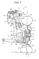
- the suspension system 10 of this embodiment is a front suspension system of the double wish-bone type and is used for an automotive vehicle of the type wherein a driving force from an engine (not shown) is transmitted to front wheels, for example, of the front engine front wheel drive (FF) type or the four wheel drive (4WD) type.
- the suspension system 10 is comprised of a steering knuckle 12 for rotatably supporting a front wheel 14 provided with a brake disc 16.
- the knuckle 12 rotatably journals throuh a bearing 18 an axle shaft 20 of the wheel 14 which shaft 20 is connected through a constant velocity joint 22 to a drive shaft 24 driven under the driving force from the engine.
- the lower section 12a of the knuckle 12 is connected through a ball joint 26 to the outboard end section of a lower control arm 28 whose inboard end section is connected through a rubber insulation bushing 30 to a bracket (not shown) of a vehicle body 31.
- the ball joint 26 includes a ball stud 26a secured to the knuckle lower section 12a, and a retainer 26b which is secured to the outboard end section of the lower control arm 28.
- the upper section 12b of the knuckle 12b is rotatably connected to an extension bracket (member) 32. More specifically, the knuckle upper section 12b is formed with an upwardly extending shaft portion 12c.
- a lower end section 32a of the extension member 32 is formed with a cylindrical portion 32c which is fitted through a bushing 34 (made of plastic) around the shaft portion 12c so as to be rotatable relative to the shaft portion 12c.
- a bushing 34 made of plastic
- the center axis of the knuckle shaft portion 12c is aligned with the center axis of the ball stud 26a of the ball joint 26.
- the center axis of the knuckle shaft portion 12c also serves as the axis of rotation of a joint including the bushing 34 and the cylindrical portion 32c of the extension member 32.
- a straight line or axis aligned with the center axe of the knuckle shaft portion 12c and the center axis of the ball joint 26 serves as a steering axis or kingpin axis 36.
- the bushing 34 may be formed of a material other than plastic or may be replaced with a plain bearing such as a bearing metal. Additionally, a rolling bearing may be used in place of the bushing 34.
- the joint between the knuckle 12 and the extension bracket 32 has been shown and described as using the bushing 34, it will be understood that the joint may be replaced with other means for connecting the knuckle 12 to the extension member 32 in a condition in which the center of rotation of the joint is aligned with the steering axis 36.
- the extension bracket 32 is extended upward and curved outward relative to the vehicle body 31 in a manner to surround the upper section of the wheel 14 so that the upper end section 32b of the extension bracket 32 reaches a position above the upper-most section 14a of the wheel 14.
- the upper end section 32b is swingably connected through a rubber insulation bushing 38 to the outboard end section of an upper control arm 40 whose inboard end section is swingably connected through a rubber insulation bushing 42 to a bracket (not shown) of the vehicle body 31. It will understood that the joint between the extension bracket 32 and the upper control arm 40 is sufficient to be one using the rubber insulation bushing 38 because the extension member 32 is merely swingable relative to the upper bracket arm 40.
- a shock absorber 44 is generally vertically installed between the vehicle body 31 and the lower control arm 7 in such a manner as to be generally parallel with the knuckle shaft portion 12c and the extension bracket 32.
- the upper end section of the shock absorber 44 is connected through a mount rubber 46 to the vehicle body 31.
- a coil spring 48 is disposed coaxially around the shock absorber 44.
- the lower end section of the shock absorber 44 is secured through a fork 50 and rubber insulation bushings 52 to the lower control arm 28. More specifically, the shock absorber lower end section is securely supported at the upper end section of the form 50 which is bifurcated to form two leg sections 50a (only one leg section shown) between which the drive shaft 24 is located thereby to prevent interfernce between the fork 50 and the drive shaft 24.
- shock absorber 44 has been shown and described as being connected at its lower end side to the lower control arm 28, it will be appreciated that the lower end side of the shock absorber may be attached to the extension bracket 32. In this case, load applied to the lower control arm 28 is minimized thereby allowing the strength of the lower control arm and the attaching section therefor to be lowered while reducing the weight of them. Additionally, no bifurcated fork is required.
- a center line 54 of the wheel 14 crosses the steering axis 36 at a position above a plane 56 at which the wheel (tire) 14 is in contact with the ground or road surface as illustrated in Fig. 1. Furthermore, the steering axis 36 intersects the plane 56 at a position lying outward of the wheel center line 54 thereby to set so-called negative scrub radius. It is to be noted that since the steering axis 36 is determined by locations of both the joint between the knuckle 12 and the extension bracket 32 and the joint between the knuckle 12 and the lower control arm 28, setting the scrub radius positive, negative or zero is not related to the arrangement of the upper control arm 40.
- the rubber insulation bushing 38 between the upper control arm 40 and the extension bracket 32 can be located without restraint from the steering axis 36.
- the rubber insulation bushing 38 is located above the wheel 14 so as to project outward relative to the vehicle body so that the rubber insulation bushing 38 and the wheel 14 overlap each other in the direction of width of the vehicle. This ensures a sufficient length to obtain an appropriate wheel alignment while locating the inboard end section of the upper control arm 40 at a position near the outside of the vehicle in the direction of width of the vehicle. This is a reason why the width of a tire house is minimized thereby to enlarge the width of an engine compartment.
- the upper control arm 40 minimizes the difference in length between it and the lower contol arm 28, thereby making possible to obtain the optimum wheel alignment.
- the vertical distance between the upper and lower control arms 40, 28 can be enlarged, variation of camber angle and caster angle due to assembly error of the suspension component parts can be minimized while suppressing development of variation of the camber angle during vertical movement of the wheel 14.
- the rigidity of both the arms 40, 28 increases proportional to the square of the distance between the both the arms, and therefore the rigidity of them is enlarged thereby improving the marginal performance of camber angle variation.
- the weight of the vehicle body is supported by the wheel 14 through the mount rubber 46, the coil spring 48, an outer cylinder of the shock absorber 44, the lower control arm 28 and the knuckle 3.
- the vertical movement of the wheel 14 can be damped under expansion and contraction of the shock absorber 44 and absorbed under deflection of the coil spring 48.
- the knuckle 12 and the extension bracket 32 make their vertical movement together with the wheel 14, so that the lower and upper control arms 40, 28 swing vertically.
- the shock absorber 44 and the coil spring 48 make their expansion and contraction.
- the extension bracket 32 makes only the above-mentioned vertical movement so that its relative movement to the upper control arm 40 is only swinging, a ball joint is unnecesary for the joint between the extension bracket 32 and the upper control arm 40, so that the rubber insulation bushing 38 is sufficient for this joint.
- the rubber insulation bushing 38 is smaller in height dimension than the ball joint, and consequently the height of the wheel house is minimized thereby lowering the level of the hood of the engine compartment.
- the rubber insulation bushing is smaller by about 40 mm in height dimension than the ball joint usually used for a control arm of a double wish-bone type suspension system.
- the fact that no rotation is made in the extension bracket 32 during vehicle steering leads to the fact of making no relative displacement of the shock absorber 44 and the coil spring 48 to the extension bracket 32 therby to prevent interference therebetween.
- the distance between the shock absorber 44 and the extension bracket 32 is minimized, thus making possible to minimize the width of the wheel house and accordingly to enlarge the engine compartment in combination with the fact of increased freedom of location of the upper control arm 40.
- relative displacement force developed between the vehicle body 31 and the wheel 14 acts along an extension of he steering axis 36 on the upper control arm 40.
- the relative displacement force is input to a point P positioned midway between the inboard and outboard end sections of the upper control arm 40.
- the suspension system of the present invention offers jointly both the advantageous effects of the above-discussed first and second prior arts as shown in Table 1, and additionally offers the unique advantageous effects summerized as follows:
- Fig. 2 illustrates a second embodiment of the suspension system according to the present invention, similar to the first embodiment with the exception that the joint between the knuckle upper section 12b and the extension bracket 32 includes two ball joints 60A, 60B.
- ball studs 62 of the two ball joints 60A, 60B are secured to the lower end section 32a of the extension bracket 32, while retainers 64 of the two ball joints are secured to the upper section 12b of the knuckle 12, so that the knuckle upper section 12b is rotatable relative to the extension bracket 32.
- the two ball joints 60A, 60B are located symmetrical with each other in such a manner that their center axes are capitad with each other. Additionally, the axes of the two ball joints 60A, 60B are aligned with the steering axis 36 passing through the ball joint 26 or aligned with the center axis of the ball joint 26.
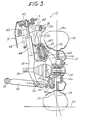
- Fig. 3 illustrates a third embodiment of the suspension system according to the present invention, which is similar to the second embodiment with the excepion that rolling bearings (ball bearings) 66A, 66B are used in place of the ball joints 60A, 60B of the second embodiment.
- the knuckle upper section 12b is formed with a cylindrical portion 12c.
- the two ball bearings 66A, 66B are disposed between the inner periphery of the cylindrical portion 12c and the outer periphery of a cylindrical sleeve 70 fitted on a bolt 68 secured to the extension member lower end section 32a.
- the ball bearings 66A, 66B are located spaced from each other and so arranged that the axis of rotation thereof and the center axis of the bolt 68 is aligned with the steering axis 36 passing through the ball joint 26 or aligned with the center axis of the ball joint 26. It will be understood that roller bearings may be used in place of the ball bearings 66A, 66B, in which tapered roller bearings are preferable in order to receive thrust.
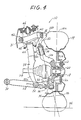
- Fig. 4 illustrates a fourth embodiment of the suspension system according to the present invention, which is similar to the first embodiment except for the location of the joint between the extension bracket 32 and the upper control arm 40.
- the upper end section 32b of the extension bracket 32 is located forward of the upper-most section 14a of the wheel (tire) 14 and swingably connected through the rubber insulation bushing 38 to the outboard end section of the upper control arm 40.
- Such a locational arrangement is indicated by "B" in Figs. 5 and 6 in which the rubber insulation bushing 38 is positioned below the level of the upper-most section 14a of the wheel 14 and one-sided laterally outward of the vehicle body in such a manner as to lie above the ground- contacting surface of the wheel (tire) 14, preventing inference with the wheel 14.
- the ruber insulation bushing location can be lowered as indicated by "B” in Fig. 5 by a vertical distance H as compared with in a case where the rubber insulation bushing 38 is situated above the wheel upper-most section 14a as indicated by “A” in Fig. 5.
- This lowers the location of the upper control arm 40 and the mount rubber 46, thereby lowering the hood 72 of the engine compartment as seen from Fig. 5.
- the extension bracket upper end section 32b (the rubber insulation bushing 38) may be otherwise located rearward of the wheel upper-most section 14a as indicated by "C” in Figs. 5 and 6.
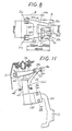
- Fig. 7 illustrates a fifth embodiment of the suspension system according to the present invention, which is similar to the first embodiment of Fig. 1 except for the arrangement of the joint between the extension bracket 32 and the upper control arm 40.
- the upper control arm 40 is generally H-shaped in plan as shown in Fig. 8 and includes two longer straight elongate sections 40a, 40b and a shorter straight elongate section 40c for integrally connecting the longer elongate sections 40a, 40b.
- the inboard end portions of the longer elongate sections 40a, 40b are respectively connected through the rubber insulation bushings 38a, 38b to the upper end section 32b of the extension bracket 32.
- each longer elongate section 40a is formed with a cylindrical part (no numeral) which is generally coaxially mounted through the bushing 42a (42b) on a rod member (no numeral) secured to the bracket 31a.
- the bushing 42a (42b) is cylindrical and interposed between the inner peripheral surface of the cylindrical part of the longer section 40a and the outer periphral surface of the rod member.
- the outboard end portion of each longer section 40a (40b) is formed with a cylindrical part (no numeral) which is generally coaxially mounted through the bushing 38a (38b) on a rod member 32d secured to the upper end section 32b of the extension bracket 32.
- the bushing 38a (38b) is generally cylindrical and interposed between the inner peripheral surface of the cylindrical part of the longer section 40a (40b) and the outer peripheral surface of the rod member 32d.
- Both the rubber insulation bushing 42a, 42b are positioned generally coaxial along a first common axis indicated by a dot-dash line in Fig. 8, and similarly both the rubber insulation bushings 38a, 38b are positioned generally coaxial along a second common axis indicated by a dot-dash line in Fig. 8, in which the first and second common axes are parallel with each other.
- the upper end section 32b and the rod member 32d of the extension bracket 32 is formed generally into the T-shape so that the extension bracket upper end section 32b is integrally connected to he rod member 32c at an intermedite part between the bushings 38a, 38b.
- the upper control arm 40 is pivotally connected at its inboard end section with the vehicle body side and pivotally connected at its outboard end section to the extension bracket upper end section 32b.
- the weight of the vehicle body is supproted by the wheels 14 through the mount rubber 46, the fork 50, the lower control arm 28 and the knuckle 12. Vertical movement of the wheel 14 is damped under expansion and contraction of the shock absorber 44 and absorbed under deflection of the coil spring 48.
- the rigidity G p at the force input point P is increased and improved as compared with in other suspension systems as discussed hereinafter with reference to Figs. 9 and 10.
- the above-discussed first prior art double link type suspension system (disclosed in Japanese Patent Provisional Publication No. 59-96007) is provided with an upper control arm 101 through which a knuckle is connected to a vehicle body.
- bushings 102a, 102b respectively receive 0.5 kg fore-and-aft direction components (F 2a , F 2b ) of forces in the fore-and-aft direction of the vehicle and 1.5 kg lateral direction components (S 2a , S 2b ) of forces in the rightward-and-leftward direction of the vehicle.
- F 2a , F 2b fore-and-aft direction components
- S 2a , S 2b lateral direction components
- the element for setting a steering axis and the element for setting camber angle are separated from each other thereby to increase freedom of selection of position of the upper control arm outboard end section, thus minimizing the width and the height of a wheel house to enlarge the width of an engine compartment while setting wheel alignment appropriate.
- the two bushings 106a, 106b respectively receive 0.5 kg force-and-aft direction components (F 6a , F 6b ) of forces in the vehicle fore-and-aft direction and 1 kg lateral components (S 6a , S 6b ) of forces in the vehicle rightward-and-leftward direction. These lateral components of force is transmitted as vehicle body input force to the vehicle body.
- the rigidity G p at the force input point P of the upper control arm 40 is about 1.5 times of that of the prior art arrangement of Fig. 9 and about 4 times of that of the arrangement of Fig. 10.
- relative displacement force developed between the vehicle body and the wheel during vehicle braking or the like is adapted to input to the point P at which the steering axis intersects the plane of the upper control arm 40. Accordingly, such a force input point is near the vehicle body as compared with a case where force input is made at the outboard end section of the upper control arm, and therefore load to an upper control arm attaching section of the vehicle body side is lowered.
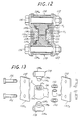
- Figs. 11 to 13 illustrate a sixth embodiment of the suspension system according to the present invention, which is similar to the fifth embodiment of Fig. 7 with the exception that the lower section of the shock absorber 44 is rotatably supported by the upper section 12b of the knuckle 12, and the lower end section 32a ⁇ of the extension member 32 is fixedly secured to the outer cylinder of the shock absorber 44. More specifically, in this embodiment, the knuckle upper section 12b is formed with a cylindrical portion 12m whose axis is generally vertical.
- the cylindrical portion 12m has a generally vertically extending through-hole 12n which includes a central small-diameter hole section H1 and two large-diameter hole sections H1 which are located on the opposite sides of the hole section H2 and opened to the opposite end faces of the cylindrical portion 12m.
- a step section including an annular flat surface S is formed between the hole sections H1, H2.
- An O-ring 131 is fitted on the peripheral surface of each large-diameter hole section H2.
- An annular sliding washer 132 is disposed in contact with the flat surface S of the step section.
- a sliding bushing 133 is disposed within the small-diameter hole section H1 and interposed between the oppositely positioned sliding washers 132.
- the axis of the cylindrical portion 12m is aligned with the steering axis 36 aligned with the axis of the ball joint 26 for connecting the knuckle lower section 12a and the lower control arm 28 though not shown.
- each support member 134 includes a generally horizontally extending cylindrical boss section 134a having a through-hole (no numeral).
- a large diameter cylindridal projection 134b is integrally formed on the side cylindrical outer face of the boss section 134a.
- a small-diameter cylindrical projection 134c is integrally formed on the top end face of the large-diameter cylindrical projection 134b. The projections 134b, 134c of the supporting member 134 is inserted into the hole 12n in such a manner that the cylindrical projections 134b, 134c are respectively located in the hole sections H2, H1.
- te small-diameter cylindrical projection 134c is rotatably fitted in he cylindrical sliding bushing 133.
- the large diameter projection 134b is contacted at its end face with the annular sliding washer 132 and at its outer periphery with the O-ring 131.
- a band member 135 for securely grasping the lower section of the shock absorber 44 is provided to be secured to the support members 34 in such a manner that the support members 134 are interposed between the opposite end sections 135a, 135b. More specifically, the opposite end sections 135a, 135b of the band member 135 are disposed to contact with the opposite end faces of each support member 134 so that openings (no numerals) of the band member end section 135a, 135b meet the through-holes of the support member cylindrical boss sections 34a, resectively, upon which each bolt 136 is inserted through the met opening and through-hole and tighened by engaging a nut 37 screwed on the bolt 136.
- the shock absorber 44 is attached to the upper section 12b of the knuckle 12 to be relatively rotatable around the steering axis (not shown) passing through the ball joint 26 between the knuckle lower section 12a and the lower control arm 28. It will be appreciated that, with the arrangement of Figs. 12 and 13, the play of the joint between the shock absorber 44 and knuckle 12 can be securely omitted thereby obtaining smooth relatively rotatable joint therebetween without using shims which have been required in such a joint.
Landscapes
- Engineering & Computer Science (AREA)
- Mechanical Engineering (AREA)
- Chemical & Material Sciences (AREA)
- Combustion & Propulsion (AREA)
- Transportation (AREA)
- Vehicle Body Suspensions (AREA)
Applications Claiming Priority (6)
| Application Number | Priority Date | Filing Date | Title |
|---|---|---|---|
| JP166127/86 | 1986-07-15 | ||
| JP16612786A JPS6322713A (ja) | 1986-07-15 | 1986-07-15 | ダブルリンク式サスペンシヨン装置 |
| JP124957/86U | 1986-08-14 | ||
| JP12495786U JPS6330204U (de) | 1986-08-14 | 1986-08-14 | |
| JP19100486A JPS6346906A (ja) | 1986-08-14 | 1986-08-14 | ダブルリンク式サスペンシヨン装置 |
| JP191004/86 | 1986-08-14 |
Publications (3)
| Publication Number | Publication Date |
|---|---|
| EP0253383A2 true EP0253383A2 (de) | 1988-01-20 |
| EP0253383A3 EP0253383A3 (en) | 1988-10-19 |
| EP0253383B1 EP0253383B1 (de) | 1992-03-18 |
Family
ID=27315009
Family Applications (1)
| Application Number | Title | Priority Date | Filing Date |
|---|---|---|---|
| EP87110242A Expired EP0253383B1 (de) | 1986-07-15 | 1987-07-15 | Aufhängungssystem vom Typ mit zwei Aufhängungsarmen |
Country Status (3)
| Country | Link |
|---|---|
| US (1) | US4810002A (de) |
| EP (1) | EP0253383B1 (de) |
| DE (1) | DE3777477D1 (de) |
Cited By (5)
| Publication number | Priority date | Publication date | Assignee | Title |
|---|---|---|---|---|
| EP0312997A1 (de) * | 1987-10-19 | 1989-04-26 | Nissan Motor Co., Ltd. | Doppelquerlenkeraufhängung mit Stabilisator |
| EP0312998A1 (de) * | 1987-10-19 | 1989-04-26 | Nissan Motor Co., Ltd. | Doppelquerlenkeraufhängung |
| US5062655A (en) * | 1989-11-20 | 1991-11-05 | Dr.Ing.H.C.F. Porsche Aktiengesellschaft | Wheel suspension system having a lower bearing with two ball joints |
| FR2723887A1 (fr) * | 1994-08-25 | 1996-03-01 | Peugeot | Suspension d'une roue directrice de vehicule |
| EP1724130A1 (de) * | 2005-05-20 | 2006-11-22 | ArvinMeritor Technology, LLC | Konsole für eine Luftfeder |
Families Citing this family (15)
| Publication number | Priority date | Publication date | Assignee | Title |
|---|---|---|---|---|
| US4753455A (en) * | 1986-07-15 | 1988-06-28 | Nissasn Motor Co., Ltd. | Double link type suspension system |
| JPH0524563Y2 (de) * | 1986-12-16 | 1993-06-22 | ||
| US5375870A (en) * | 1992-12-17 | 1994-12-27 | Chrysler Corporation | Mounting structure of a front suspension system |
| US5820150A (en) * | 1993-04-14 | 1998-10-13 | Oshkosh Truck Corporation | Independent suspensions for lowering height of vehicle frame |
| US6173978B1 (en) | 1999-05-07 | 2001-01-16 | Zero Roll Suspension Corporation | Zero roll suspension system |
| US20040046350A1 (en) * | 2001-05-21 | 2004-03-11 | Wagner Engineering, Llc | Method and apparatus for suspending a vehicular wheel assembly |
| KR100476191B1 (ko) * | 2001-12-06 | 2005-03-16 | 현대자동차주식회사 | 자동차의 멀티 링크 현가장치용 더블 볼 죠인트 |
| US20040178600A1 (en) | 2003-03-10 | 2004-09-16 | Wagner Engineering, Llc | Method and apparatus for suspending a vehicle |
| CN100581911C (zh) * | 2004-03-30 | 2010-01-20 | 本田技研工业株式会社 | 车辆及其链条间隙调节装置 |
| US20060108763A1 (en) * | 2004-11-23 | 2006-05-25 | Ray Michael A | Suspension control arm assembly for vehicles |
| US20080036168A1 (en) * | 2005-11-30 | 2008-02-14 | Wagner J T | Method and apparatus for suspending a vehicle |
| US7559403B2 (en) | 2006-04-05 | 2009-07-14 | Schmitz Geoffrey W | Modular, central frame, offset, dual control arm independent suspension and suspension retrofit |
| US7793954B2 (en) * | 2007-06-22 | 2010-09-14 | Radar Industries, Inc. | Suspension system for a vehicle |
| JP6475217B2 (ja) * | 2016-11-04 | 2019-02-27 | 本田技研工業株式会社 | スプリングシートラバー |
| CA3194437A1 (en) * | 2020-09-30 | 2022-04-07 | Martin Heon | Front suspension assembly for an off-road vehicle |
Family Cites Families (5)
| Publication number | Priority date | Publication date | Assignee | Title |
|---|---|---|---|---|
| FR1573273A (de) * | 1968-05-15 | 1969-07-04 | ||
| JPS5996008A (ja) * | 1982-11-24 | 1984-06-02 | Honda Motor Co Ltd | 車両用懸架装置 |
| JPS5996007A (ja) * | 1982-11-24 | 1984-06-02 | Honda Motor Co Ltd | 車両のサスペンシヨンア−ム取付構造 |
| JPS59143706A (ja) * | 1983-02-04 | 1984-08-17 | Nissan Motor Co Ltd | 独立懸架装置 |
| JPS60135314A (ja) * | 1983-12-23 | 1985-07-18 | Mazda Motor Corp | ウイツシユボ−ン式サスペンシヨン |
-
1987
- 1987-07-10 US US07/072,047 patent/US4810002A/en not_active Expired - Fee Related
- 1987-07-15 DE DE8787110242T patent/DE3777477D1/de not_active Expired - Fee Related
- 1987-07-15 EP EP87110242A patent/EP0253383B1/de not_active Expired
Cited By (8)
| Publication number | Priority date | Publication date | Assignee | Title |
|---|---|---|---|---|
| EP0312997A1 (de) * | 1987-10-19 | 1989-04-26 | Nissan Motor Co., Ltd. | Doppelquerlenkeraufhängung mit Stabilisator |
| EP0312998A1 (de) * | 1987-10-19 | 1989-04-26 | Nissan Motor Co., Ltd. | Doppelquerlenkeraufhängung |
| US4883287A (en) * | 1987-10-19 | 1989-11-28 | Nissan Motor Co., Ltd. | Double link type suspension system with stabilizer bar |
| US4934729A (en) * | 1987-10-19 | 1990-06-19 | Nissan Motor Co., Ltd. | Double link type suspension system |
| US5062655A (en) * | 1989-11-20 | 1991-11-05 | Dr.Ing.H.C.F. Porsche Aktiengesellschaft | Wheel suspension system having a lower bearing with two ball joints |
| FR2723887A1 (fr) * | 1994-08-25 | 1996-03-01 | Peugeot | Suspension d'une roue directrice de vehicule |
| EP1724130A1 (de) * | 2005-05-20 | 2006-11-22 | ArvinMeritor Technology, LLC | Konsole für eine Luftfeder |
| US7819411B2 (en) | 2005-05-20 | 2010-10-26 | Arvinmeritor Technology, Llc | Six link independent suspension for a drive axle |
Also Published As
| Publication number | Publication date |
|---|---|
| DE3777477D1 (de) | 1992-04-23 |
| EP0253383B1 (de) | 1992-03-18 |
| US4810002A (en) | 1989-03-07 |
| EP0253383A3 (en) | 1988-10-19 |
Similar Documents
| Publication | Publication Date | Title |
|---|---|---|
| EP0253383B1 (de) | Aufhängungssystem vom Typ mit zwei Aufhängungsarmen | |
| EP0253384B1 (de) | Aufhängungssystem vom Typ mit zwei Aufhängungsarmen | |
| US4046403A (en) | Strut type independent suspension system for automobiles | |
| US4875703A (en) | Double link type suspension including a stabilizer bar | |
| EP0312997B1 (de) | Doppelquerlenkeraufhängung mit Stabilisator | |
| US4802688A (en) | Double link type suspension system | |
| US4415178A (en) | Suspension for motor vehicles | |
| US3333654A (en) | Motor vehicle suspension | |
| US4456282A (en) | Independent rear wheel suspension with a toe angle controlling trailing arm | |
| US4934729A (en) | Double link type suspension system | |
| US4784406A (en) | Friction reducing automotive suspension stabilizer bar | |
| JPS6164506A (ja) | ストラツト型サスペンシヨン | |
| US4565389A (en) | Vehicle suspension system | |
| US4971296A (en) | Vehicle suspension mechanism | |
| US4865350A (en) | Vehicle suspension system | |
| US5238261A (en) | Suspension of steering vehicle wheel having z-type upper arm assembly | |
| US5439244A (en) | Suspension apparatus for an automotive vehicle | |
| US4097057A (en) | Independent suspension system | |
| JPS61263809A (ja) | リヤサスペンシヨン | |
| KR910006555B1 (ko) | 자동차용 현가의 부시장치 | |
| US4852904A (en) | Vehicle suspension system | |
| JPH057202B2 (de) | ||
| KR100316892B1 (ko) | 자동차 현가장치의 로워 컨트롤 아암 | |
| JPH0737928Y2 (ja) | 自動車の後輪懸架装置 | |
| JPH0357528Y2 (de) |
Legal Events
| Date | Code | Title | Description |
|---|---|---|---|
| PUAI | Public reference made under article 153(3) epc to a published international application that has entered the european phase |
Free format text: ORIGINAL CODE: 0009012 |
|
| 17P | Request for examination filed |
Effective date: 19870715 |
|
| AK | Designated contracting states |
Kind code of ref document: A2 Designated state(s): DE GB |
|
| PUAL | Search report despatched |
Free format text: ORIGINAL CODE: 0009013 |
|
| AK | Designated contracting states |
Kind code of ref document: A3 Designated state(s): DE GB |
|
| 17Q | First examination report despatched |
Effective date: 19890627 |
|
| GRAA | (expected) grant |
Free format text: ORIGINAL CODE: 0009210 |
|
| AK | Designated contracting states |
Kind code of ref document: B1 Designated state(s): DE GB |
|
| REF | Corresponds to: |
Ref document number: 3777477 Country of ref document: DE Date of ref document: 19920423 |
|
| PLBE | No opposition filed within time limit |
Free format text: ORIGINAL CODE: 0009261 |
|
| STAA | Information on the status of an ep patent application or granted ep patent |
Free format text: STATUS: NO OPPOSITION FILED WITHIN TIME LIMIT |
|
| 26N | No opposition filed | ||
| PGFP | Annual fee paid to national office [announced via postgrant information from national office to epo] |
Ref country code: GB Payment date: 19980706 Year of fee payment: 12 |
|
| PGFP | Annual fee paid to national office [announced via postgrant information from national office to epo] |
Ref country code: DE Payment date: 19980724 Year of fee payment: 12 |
|
| PG25 | Lapsed in a contracting state [announced via postgrant information from national office to epo] |
Ref country code: GB Free format text: LAPSE BECAUSE OF NON-PAYMENT OF DUE FEES Effective date: 19990715 |
|
| GBPC | Gb: european patent ceased through non-payment of renewal fee |
Effective date: 19990715 |
|
| PG25 | Lapsed in a contracting state [announced via postgrant information from national office to epo] |
Ref country code: DE Free format text: LAPSE BECAUSE OF NON-PAYMENT OF DUE FEES Effective date: 20000503 |