EP0252484A2 - Medizinischer Sterilisator - Google Patents
Medizinischer Sterilisator Download PDFInfo
- Publication number
- EP0252484A2 EP0252484A2 EP87109753A EP87109753A EP0252484A2 EP 0252484 A2 EP0252484 A2 EP 0252484A2 EP 87109753 A EP87109753 A EP 87109753A EP 87109753 A EP87109753 A EP 87109753A EP 0252484 A2 EP0252484 A2 EP 0252484A2
- Authority
- EP
- European Patent Office
- Prior art keywords
- steam
- solar
- pressure pot
- steam pressure
- water
- Prior art date
- Legal status (The legal status is an assumption and is not a legal conclusion. Google has not performed a legal analysis and makes no representation as to the accuracy of the status listed.)
- Granted
Links
Images
Classifications
-
- A—HUMAN NECESSITIES
- A61—MEDICAL OR VETERINARY SCIENCE; HYGIENE
- A61L—METHODS OR APPARATUS FOR STERILISING MATERIALS OR OBJECTS IN GENERAL; DISINFECTION, STERILISATION OR DEODORISATION OF AIR; CHEMICAL ASPECTS OF BANDAGES, DRESSINGS, ABSORBENT PADS OR SURGICAL ARTICLES; MATERIALS FOR BANDAGES, DRESSINGS, ABSORBENT PADS OR SURGICAL ARTICLES
- A61L2/00—Methods or apparatus for disinfecting or sterilising materials or objects other than foodstuffs or contact lenses; Accessories therefor
- A61L2/24—Apparatus using programmed or automatic operation
-
- A—HUMAN NECESSITIES
- A61—MEDICAL OR VETERINARY SCIENCE; HYGIENE
- A61L—METHODS OR APPARATUS FOR STERILISING MATERIALS OR OBJECTS IN GENERAL; DISINFECTION, STERILISATION OR DEODORISATION OF AIR; CHEMICAL ASPECTS OF BANDAGES, DRESSINGS, ABSORBENT PADS OR SURGICAL ARTICLES; MATERIALS FOR BANDAGES, DRESSINGS, ABSORBENT PADS OR SURGICAL ARTICLES
- A61L2/00—Methods or apparatus for disinfecting or sterilising materials or objects other than foodstuffs or contact lenses; Accessories therefor
- A61L2/02—Methods or apparatus for disinfecting or sterilising materials or objects other than foodstuffs or contact lenses; Accessories therefor using physical phenomena
- A61L2/04—Heat
- A61L2/06—Hot gas
-
- A—HUMAN NECESSITIES
- A61—MEDICAL OR VETERINARY SCIENCE; HYGIENE
- A61L—METHODS OR APPARATUS FOR STERILISING MATERIALS OR OBJECTS IN GENERAL; DISINFECTION, STERILISATION OR DEODORISATION OF AIR; CHEMICAL ASPECTS OF BANDAGES, DRESSINGS, ABSORBENT PADS OR SURGICAL ARTICLES; MATERIALS FOR BANDAGES, DRESSINGS, ABSORBENT PADS OR SURGICAL ARTICLES
- A61L2/00—Methods or apparatus for disinfecting or sterilising materials or objects other than foodstuffs or contact lenses; Accessories therefor
- A61L2/26—Accessories or devices or components used for biocidal treatment
Definitions
- the invention relates to a medical sterilizer with a sterilization container designed as a steam pressure pot with a pressure control valve.
- the invention has for its object to provide a medical sterilizer that can be operated safely with the aid of a solar system and in which the steam pressure pot, which is sufficiently long and heated as a sterilization container, is decoupled from the sterilized medical devices remaining therein and by the next steam pressure pot is to be replaced with other medical devices used therein.
- the solution according to the invention in the sterilizer mentioned at the outset with a sterilization container designed as a steam pressure pot with a pressure control valve is that the steam pressure pot is directly switched on by an automatic closure of both line pieces having hose couplings in the primary steam circuit of a solar system when the entire system is controlled via the pressure control valve of the steam pressure pot.
- the steam generated directly in the solar system preferably from water, can be used directly for sterilization in the steam pressure pot. Because of the direct feed of the external namely in the solar system - generating steam in the steam pressure pot is not required in this solar-powered steam circuit, which is used directly for sterilization.
- Another advantage is that the solar system does not require any special control, because the control and safety device, which is required anyway on the steam pressure pot, must be used to control the entire system. Since the control valve generally assigned to a steam pressure pot responds to the pressure of the steam contained in the pot, the temperature in the device according to the invention is controlled not only in the steam pressure pot but also in the solar system via the pressure.
- a still further advantage of the invention is that the primary steam circuit of the solar system is to be connected to the steam pressure pot via hose couplings, which have an automatic closure of both line sections.
- hose couplings which have an automatic closure of both line sections.
- the steam pressure pot can be manually disconnected from the solar-powered steam circuit and brought to the place of use. It is not necessary dig to open the pot and take out the sterilized good before it is really needed.
- the hose couplings provided according to the invention allow a freshly loaded steam pressure pot to be switched into the circuit without interrupting the steam generation in the solar part. This makes it possible to make optimal use of the solar energy that is only available for around seven to eight hours a day.
- the steam can be directed to an air-cooled condenser or air heat exchanger via a three-way tap and liquefied there when it is not required for sterilization.
- the condensate can be collected separately as distilled water or returned to the solar section.
- the air heat exchanger can also be designed as a water heat exchanger. This allows better heat dissipation and thus a higher distillation performance to be achieved and / or the heat can be useful, e.g. B. for heating domestic water.
- Another important advantage of the sterilizer according to the invention is that because of its simple construction, the device practically does not allow any possibility of triggering an accident due to operating errors. All parts heated by the steam can be isolated. Because of the self-closing valves in the connection or hose couplings, steam cannot escape when coupling or uncoupling. If the air cooler provided in parallel with the steam pressure pot is switched on via a temperature-controlled three-way valve in the solar-powered steam circuit, Despite the absence of a special control valve in the solar part of the system, no overheating or excessive pressure can occur even if a steam pressure pot is not switched on in the circuit.
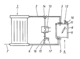
- water vapor generated in a solar system designated overall by 1 is passed via a steam supply line 2 and a hose coupling 3 into a steam pressure pot designated overall by 4 and via a further hose coupling 5 and a condensate or steam discharge line 6 to the solar system 1 returned.
- the solar system 1 should contain liquid, water, in particular drinking water, as a heat transfer medium.
- the solar system 1 can have a water supply line 7.
- Conventional solar systems with a high-temperature flat-plate collector are possible, which can generate a steam temperature of 130 ° C and more.
- the systems should be designed or selected so that they can be operated with sufficient energy output for most of the day without adapting to the position of the sun.
- a device with a pot 9 holding the medical devices 8 with a lid 10 and lid clamp 11 can be used as a steam pressure pot 4.
- the steam pressure pot 4 should also be equipped with a control and safety valve 12, which allows the temperature inside the pot to be controlled via the pressure. If the Solar system 1 is connected to the steam pressure pot 4 via the lines 2 and 6, the pressure present in it is also controlled via the control valve 12.
- hose couplings 3 and 5 so that they close automatically when uncoupled.
- the coupling pieces attached to the lines 2 and 6 should also be equipped with such a self-closing valve, so that the pressure in the solar system 1 does not drop when a steam pressure pot 4 is uncoupled and / or the operator can be injured by escaping steam.
- an air cooler 13 can be switched on via a three-way valve 14 parallel to the section of the solar steam circuit assigned to the steam pressure pot 4.
- the valve 14 can preferably be designed as a temperature-controlled three-way valve for alternative switching of the solar-powered steam circuit from the steam pressure pot 4 to the air cooler 13, such that the air cooler 13 serves as protection against overheating.
- the route of the solar-powered steam circuit with the air cooler 13 can also be used as an air heat exchanger for producing distilled water.
- a three-way tap 16 with outlet 17 for the distilled water can be installed in the discharge line 15 of the air heater 13 .
- This auxiliary part of the system is preferably activated when the sterilization campaign to be completed in each case has ended and there is still sunshine duration left for energy generation.
- the air cooler is designed as a water / water heat exchanger, there is a very good heat dissipation and, on the other hand, the possibility of using the waste heat to heat up other products, e.g. B. of domestic water.
Landscapes
- Health & Medical Sciences (AREA)
- Epidemiology (AREA)
- Life Sciences & Earth Sciences (AREA)
- Animal Behavior & Ethology (AREA)
- General Health & Medical Sciences (AREA)
- Public Health (AREA)
- Veterinary Medicine (AREA)
- Apparatus For Disinfection Or Sterilisation (AREA)
- Materials For Medical Uses (AREA)
Abstract
Description
- Die Erfindung betrifft einen medizinischen Sterilisator mit einem als Dampfdrucktopf mit Druckregelventil ausgebildeten Sterilisationsbehälter.
- In Gebieten mit schwacher oder gar keiner Infrastruktur, in denen also insbesondere auch Elektrizität nicht zur Verfügung steht, können medizinische Geräte und dergleichen in einem Dampfdrucktopf entkeimt werden. Der Wasser und die jeweils zu entkeimenden Teile enthaltende Dampfdrucktopf kann auf einem mit am Ort vorhandenen Heizmitteln oder mit Gas betriebenen Herd bzw. Brenner erhitzt werden. Das Beschaffen bzw. Herantransportieren des herkömmlichen Heizmaterials ist mühsam und aufwendig und erzeugt bei der Anwendung erhebliche Abwärme, die zu der ohnehin meist hohen Umgebungstemperatur noch zusätzlich unangenehm wirkt.
- In den relativ heißen Zonen der Erde könnte die zum Betrieb eines medizinischen Sterilisators erforderliche Energie mit Hilfe einer Solaranlage, wie sie beispielsweise in der DE OS 28 16 945 oder in der internationalen Veröffentlichung (PCT) WO 83/02149 beschrieben wird, gewonnen werden. Um in einem solchen Falle einen nennenswerten Gesamtwirkungsgrad unter Einbezug des Wärmetauschers zwischen Primärkreislauf der Solaranlage und Dampfdrucktopf zu erhalten, müßte der letztere in spezieller Weise den Erfordernissen eines möglichst verlustfreien Wärmetausches angepaßt werden.
- Von der Weltgesundheitsorganisation (WHO) sind für eine umfangreiche Impfung in den heißen Entwicklungsländern verbindliche Dampfdrucktöpfe zum Sterilisieren medizinischer Geräte und dergleichen entwickelt und anerkannt worden. Diese Dampfdrucktöpfe lassen sich nicht ohne weiteres den Forderungen eines einen annehmbaren Wirkungsgrad aufweisenden Wärmetausches mit dem Primärkreislauf einer Solaranlage anpassen. Insbesondere bereitet es erhebliche Schwierigkeiten und einen entsprechend hohen Aufwand, die jeweiligen Heizmittel so dem genormten Dampfdrucktopf anzupassen, da der Topf auf einfache Weise an der Heizstelle auszutauschen ist.
- Der Erfindung liegt die Aufgabe zugrunde, einen medizinischen Sterilisator zu schaffen, der gefahrlos unter Zuhilfenahme einer Solaranlage zu betreiben ist und bei dem der jeweils ausreichend lange und hoch erhitzte, als Sterilisationsbehälter ausgebildete Dampfdrucktopf mit darin verbleibenden, entkeimten medizinischen Geräten abgekoppelt und durch den nächsten Dampfdrucktopf mit weiteren darin eingesetzten medizinischen Geräten zu ersetzen ist. Die erfindungsgemäße Lösung besteht bei dem eingangs genannten Sterilisator mit einem als Dampfdrucktopf mit Druckregelventil ausgebildeten Sterilisationsbehälter darin, daß der Dampfdrucktopf über einen automatischen Verschluß beider Leitungsstücke aufweisende Schlauchkupplungen in den primären Dampfkreislauf einer Solaranlage bei Steuerung des Gesamtsystems über das Druckregelventil des Dampfdrucktopfes unmittelbar eingeschaltet ist.
- Durch die Erfindung wird erreicht, daß der in der Solaranlage unmittelbar, vorzugsweise aus Wasser, erzeugte Dampf direkt zum Sterilisieren im Dampfdrucktopf heranzuziehen ist. Wegen der direkten Einspeisung des extern- nämlich in der Solaranlage - erzeutgen Dampfes in den Dampfdrucktopf werden in diesem solarbetriebenen und unmittelbar zum Sterilisieren eingesetzten Dampfkreislauf Wärmetauscher nicht benötigt.
- Als weiterer Vorteil kommt hinzu, daß die Solaranlage keine besondere Regelung erfordert, weil die am Dampfdrucktopf ohnehin erforderliche Regel- und Sicherheitseinrichtung zum Steuern des ganzen Systems heranzuziehen ist. Da das einem Dampfdrucktopf im allgemeinen zugeordnete Regelventil auf den Druck des im Topf enthaltenen Dampfes anspricht, wird bei der erfindungsgemäßen Einrichtung die Temperatur nicht nur im Dampfdrucktopf sondern auch in der Solaranlage über den Druck gesteuert.
- Ein noch weiterer Vorteil der Erfindung besteht darin, daß der primäre Dampfkreislauf der Solaranlage über Schlauchkupplungen an den Dampfdrucktopf anzuschließen ist, die einen automatischen Verschluß beider Leitungsstücke besitzen. Zum erfindungsgemäßen Einbau in den primären Dampfkreislauf einer Solaranlage braucht ein genormter Dampfdrucktopf also nur mit je einer selbst schließenden Steckkupplung zum Anschluß der von der Solaranlage kommenden Dampfzuleitung zurückführenden Kondensat- bzw. Dampfleitung ausgestattet zu werden. Es bereitet keine Schwierigkeiten, solche Schlauchkupplungen an einem fertigen, genormten Dampfdrucktopf vorzusehen.
- Nach erfolgter Sterilisation kann der Dampfdrucktopf vom solarbetriebenen Dampfkreislauf manuell abgekoppelt und an den Anwendungsort gebracht werden. Es ist nicht notwen dig, den Topf zu öffnen und das sterilisierte Gut herauszunehmen, bevor es wirklich gebraucht wird. Die erfindungsgemäß vorgesehenen Schlauchkupplungen lassen es zu, einen frisch beladenen Dampfdrucktopf in den Kreislauf einzuschalten, ohne die Dampferzeugung im Solarteil zu unterbrechen. Hierdurch ist es möglich, die nur für etwa sieben bis acht Stunden pro Tag verfügbare Sonnenenergie optimal zu nutzen.
- Um jedoch unzulässige Überhitzungen im Solarteil der Anlage zu vermeiden, kann der Dampf dann, wenn er nicht zum Sterilisieren benötigt wird, über einen Drei-Wege-Hahn zu einem luftgekühlten Kondensator bzw. Luft-Wärmetauscher geleitet und dort verflüssigt werden. Das Kondensat kann als destilliertes Wasser gesondert gesammelt oder in den Solarteil zurückgeleitet werden. Der Luft-Wärmetauscher kann alternativ auch als Wasser-Wärmetauscher ausgebildet werden. Dadurch läßt sich eine bessere Wärmeabfuhr und damit eine höhere Destillationsleistung erreichen und/oder die Wärme kann nutzbringend, z. B. zum Aufheizen von Brauchwasser, verwendet werden.
- Ein weiterer wichtiger Vorteil des erfindungsgemäßen Sterilisators besteht darin, daß das Gerät wegen seines einfachen Aufbaus praktisch keine Möglichkeit zuläßt, durch Bedienungsfehler einen Unfall auszulösen. Sämtliche durch den Dampf erhitzten Teile können isoliert werden. Wegen der selbstschließenden Ventile in den Verbindungs- bzw. Schlauchkupplungen kann Dampf auch beim An- bzw. Entkuppeln nicht austreten. Wenn der parallel zu dem Dampfdrucktopf vorgesehene Luftkühler über ein temperaturgesteuertes Drei-Wege-Ventil in den solarbetriebenen Dampfkreislauf eingeschaltet wird, kann trotz Fehlens eines besonderen Regelventils in dem Solarteil der Anlage auch dann keine Überhitzung bzw. ein zu hoher Überdruck auftreten, wenn ein Dampfdrucktopf in den Kreislauf nicht eingeschaltet ist.
- Anhand der schematischen Darstellung eines Ausführungsbeispiels eines an eine Solaranlagedirekt angeschlossenen medizinischen Sterilisators werden Einzelheiten der Erfindung erläutert.
- In dem in der Zeichnung dargestellten Ausführungsbeispiel wird in einer insgesamt mit 1 bezeichneten Solaranlage erzeugter Wasserdampf über eine Dampfzuleitung 2 und eine Schlauchkupplung 3 in einen insgesamt mit 4 bezeichneten Dampfdrucktopf geleitet und über eine weitere Schlauchkupplung 5 sowie eine Kondensat- bzw. Dampfableitung 6 zur Solaranlage 1 zurückgeführt. Die Solaranlage 1 soll bei der Anwendung zum direkten Einspeisen von Dampf in den Dampfdrucktopf 4 als Wärmeträger Flüssigkeit, Wasser, insbesondere Trinkwasser, enthalten. Zum Ergänzen von Trinkwasser in dem durch die Bauteile 1 bis 6 gebildeten Dampfkreislauf kann die Solaranlage 1 eine Wasserzuleitung 7 besitzen. Es kommen übliche Solaranlagen mit Hochtemperatur-Flachkollektor in Frage, die eine Dampftemperatur von 130° C und mehr erzeugen können. Die Anlagen sollen so ausgebildet bzw. ausgewählt werden, daß sie möglichst ohne Anpassung an den Sonnenstand während des größten Teils des Tages mit ausreichender Energieabgabe zu betreiben sind.
- Als Dampfdrucktopf 4 kommt eine Vorrichtung mit einem die medizinischen Geräte 8 aufnehmenden Topf 9 mit Deckel 10 und Deckelverklammerung 11 in Frage. Der Dampfdrucktopf 4 soll außerdem mit einem Regel- und Sicherheitsventil 12 ausgestattet werden, das es erlaubt, über den Druck die Temperatur im Innern des Topfes zu steuern. Wenn die Solaranlage 1 über die Leitungen 2 und 6 an den Dampfdrucktopf 4 angeschlossen ist, wird auch der in ihr vorhandene Druck über das Regelventil 12 gesteuert.
- Wenn es erwünscht ist, den jeweiligen Dampfdrucktopf 4 nach der Sterilisationszeit von z.B. 20 Minuten bei 130° C nicht zu öffnen sondern im geschlossenen Zustand an den Ort der Anwendung zu bringen, ist es wichtig, die Schlauchkupplungen 3 und 5 so auszubilden, daß sie beim Entkuppeln automatisch verschließen. Auch die an die Leitungen 2 und 6 angesetzten Kupplungsstücke sollen mit einem solchen selbst schließenden Ventil ausgestattet werden, damit der Druck in der Solaranlage 1 nicht beim Abkuppeln eines Dampfdrucktopfs 4 abfällt und/oder die Bedienungsperson durch ausströmenden Dampf verletzt werden kann.
- Um eine Überhitzung oder einen zu großen Druck in der Solaranlage 1 beim Lösen der Schlauchkupplungen 3 und 5 zu vermeiden, kann parallel zu dem dem Dampfdrucktopf 4 zugeordneten Abschnitt des solaren Dampfkreislaufs ein Luftkühler 13 über ein Drei-Wege-Ventil 14 eingeschaltet werden. Das Ventil 14 kann vorzugsweise als temperaturgesteuertes Drei-Wege-Ventil zum alternativen Umschalten des solarbetriebenen Dampfkreislaufs vom Dampfdrucktopf 4 auf den Luftkühler 13 ausgebildet werden, derart, daß der Luftkühler 13 als Überhitzungsschutz dient.
- Die Strecke des solarbetriebenen Dampfkreislaufs mit dem Luftkühler 13 kann aber auch als Luft-Wärmetauscher zum Erzeugen von destilliertem Wasser angewendet werden. Zu diesem Zweck kann in die Ableitung 15 des Lufterhitzers 13 ein Drei-Wege-Hahn 16 mit Ablauf 17 für das destillierte Wasser eingebaut werden. Dieses Hilfsteil der Anlage wird vorzugsweise dann aktiviert, wenn die jeweils zu absolvierende Sterilisationskampagne beendet ist und noch Sonnenscheindauer zur Energiegewinnung übrig geblieben ist. Bei Ausbildung des Luftkühlers als Wasser/Wasser-Wärmetauscher ergibt sich einersetis eine sehr gute Wärmeabfuhr und andererseits die Möglichkeit einer nutzbringenden Verwendung der Abwärme zum Aufheizen anderer Produkte, z. B. von Brauchwasser.
-
- 1 = Solaranlage
- 2 = Dampfzuleitung
- 3 = Schlauchkupplung
- 4 = Dampfdrucktopf
- 5 = Schlauchkupplung
- 6 = Dampfableitung
- 7 = Wasserzuleitung
- 8 = medizinisches Gut
- 9 = Topf
- 10 = Deckel
- 11 = Deckelverklammerung
- 12 = Regelventil
- 13 = Luftkühler
- 14 = Drei-Wege-Ventil
- 15 = Ableitung
- 16 = Drei-Wege-Hahn
- 17 = Ablauf
Claims (5)
Priority Applications (1)
| Application Number | Priority Date | Filing Date | Title |
|---|---|---|---|
| AT87109753T ATE68354T1 (de) | 1986-07-07 | 1987-07-07 | Medizinischer sterilisator. |
Applications Claiming Priority (2)
| Application Number | Priority Date | Filing Date | Title |
|---|---|---|---|
| DE3622789 | 1986-07-07 | ||
| DE19863622789 DE3622789A1 (de) | 1986-07-07 | 1986-07-07 | Medizinischer sterilisator |
Publications (3)
| Publication Number | Publication Date |
|---|---|
| EP0252484A2 true EP0252484A2 (de) | 1988-01-13 |
| EP0252484A3 EP0252484A3 (en) | 1988-09-07 |
| EP0252484B1 EP0252484B1 (de) | 1991-10-16 |
Family
ID=6304582
Family Applications (1)
| Application Number | Title | Priority Date | Filing Date |
|---|---|---|---|
| EP87109753A Expired - Lifetime EP0252484B1 (de) | 1986-07-07 | 1987-07-07 | Medizinischer Sterilisator |
Country Status (3)
| Country | Link |
|---|---|
| EP (1) | EP0252484B1 (de) |
| AT (1) | ATE68354T1 (de) |
| DE (1) | DE3622789A1 (de) |
Cited By (4)
| Publication number | Priority date | Publication date | Assignee | Title |
|---|---|---|---|---|
| CN102973958A (zh) * | 2011-09-05 | 2013-03-20 | 杨欢 | 高光能密度汇聚太阳光消毒法及其消毒装置 |
| US8960183B2 (en) | 2001-02-16 | 2015-02-24 | Solar Solutions Llc | Solar water pasteurizer |
| WO2015120570A1 (zh) * | 2014-02-11 | 2015-08-20 | 刘凯 | 太阳能蒸压设备 |
| CN109027988A (zh) * | 2018-05-30 | 2018-12-18 | 昆明理工大学 | 一种太阳能高温消毒柜 |
Family Cites Families (11)
| Publication number | Priority date | Publication date | Assignee | Title |
|---|---|---|---|---|
| US3138546A (en) * | 1958-05-02 | 1964-06-23 | John G Muller | Apparatus utilizing solar energy for demineralizing water |
| US3410650A (en) * | 1966-08-25 | 1968-11-12 | Bramson Maurice | Apparatus for sterilizing articles and producing distilled water |
| DE2640135A1 (de) * | 1976-09-07 | 1978-03-09 | Bosch Gmbh Robert | Verfahren und vorrichtung zum abfuehren von ueberschusswaerme eines sonnenkollektors |
| US4193389A (en) * | 1977-11-02 | 1980-03-18 | Ku Paul H Y | Solar radiant energy umbrella |
| DE2816945A1 (de) * | 1978-04-19 | 1979-10-25 | Boettcher Alfred | Hochtemperatur-flachkollektor |
| US4498959A (en) * | 1979-11-16 | 1985-02-12 | Minoru Sakamoto | Cooling attachment for solar distiller |
| DE3149607A1 (de) * | 1981-12-15 | 1983-07-21 | Alfred Prof. Dr. 5100 Aachen Boettcher | Selbstregulierende solar-anlage |
| US4473063A (en) * | 1982-08-20 | 1984-09-25 | Mackensen Warren J | Solar heater |
| DE3321861A1 (de) * | 1983-06-16 | 1984-12-20 | Werner 8531 Lonnerstadt Reinig | Destillationsverfahren mit solarenergie und waermerueckgewinnung durch verdichter |
| DE3447315A1 (de) * | 1984-12-24 | 1986-06-26 | Dornier System Gmbh, 7990 Friedrichshafen | Anlage zum sterilisieren, insbesondere fuer medizinische zwecke |
| DE3447317A1 (de) * | 1984-12-24 | 1986-07-03 | Dornier System Gmbh, 7990 Friedrichshafen | Mit regenerativer energie, insbesondere solarenergie arbeitende anlage zum sterilisieren |
-
1986
- 1986-07-07 DE DE19863622789 patent/DE3622789A1/de not_active Withdrawn
-
1987
- 1987-07-07 EP EP87109753A patent/EP0252484B1/de not_active Expired - Lifetime
- 1987-07-07 AT AT87109753T patent/ATE68354T1/de not_active IP Right Cessation
Cited By (6)
| Publication number | Priority date | Publication date | Assignee | Title |
|---|---|---|---|---|
| US8960183B2 (en) | 2001-02-16 | 2015-02-24 | Solar Solutions Llc | Solar water pasteurizer |
| CN102973958A (zh) * | 2011-09-05 | 2013-03-20 | 杨欢 | 高光能密度汇聚太阳光消毒法及其消毒装置 |
| WO2015120570A1 (zh) * | 2014-02-11 | 2015-08-20 | 刘凯 | 太阳能蒸压设备 |
| JP2016513234A (ja) * | 2014-02-11 | 2016-05-12 | 凱 劉 | 新型太陽エネルギー蒸気圧力設備 |
| AU2014284257B2 (en) * | 2014-02-11 | 2019-01-17 | Kai Liu | Novel solar autoclave equipment |
| CN109027988A (zh) * | 2018-05-30 | 2018-12-18 | 昆明理工大学 | 一种太阳能高温消毒柜 |
Also Published As
| Publication number | Publication date |
|---|---|
| DE3622789A1 (de) | 1988-01-21 |
| EP0252484B1 (de) | 1991-10-16 |
| ATE68354T1 (de) | 1991-11-15 |
| EP0252484A3 (en) | 1988-09-07 |
Similar Documents
| Publication | Publication Date | Title |
|---|---|---|
| EP0338056B1 (de) | Einrichtung zur verhinderung des auftretens bzw. der fortpflanzung von kleinstlebewesen in brauchwasser | |
| EP0099501B1 (de) | Verfahren zum Verändern der Abgabe von elektrischer Energie eines Heizkraftwerkes ohne Beeinflussung der Wärmeabgabe an angeschlossene Wärmeverbraucher | |
| AT508086B1 (de) | Vorrichtung zur energieumwandlung nach dem orc-prinzip, orc-anlage mit einer derartigen vorrichtung und verfahren zur inbetriebnahme und/oder zum betreiben einer derartigen vorrichtung | |
| DE3430089A1 (de) | Verfahren zum ausrichten eines reinraumstromes und reinraumerzeuger | |
| EP0252484B1 (de) | Medizinischer Sterilisator | |
| DE19633574B4 (de) | Trinkwassererwärmungssystem zur thermischen Desinfektion | |
| DE102010019727B4 (de) | Verfahren und Übergabestation zur Übertragung von Wärme | |
| DE3522890C2 (de) | Vorrichtung und Verfahren zum Erzeugen steriler Luft | |
| EP1764564B1 (de) | Trinkwassererwärmungsanlage | |
| EP0285009A2 (de) | Brauereianlage | |
| DE2942937C2 (de) | Einrichtung zur Nachwärmeabfuhr und/oder zur Notkühlung einer wassergekühlten Kernreaktoranlage | |
| DE3447317C2 (de) | ||
| DE3447315C2 (de) | ||
| DE4139288A1 (de) | Warmwasserbereiter mit durchlauferhitzer und durchflussentkeimung | |
| DE102013114889A1 (de) | Zirkulationseinrichtung für Trink- oder Betriebswasser und Verfahren zur Behandlung von Trink- oder Betriebswasser | |
| DE4222550C1 (de) | Anlage zum Erwärmen von Brauchwasser und zum Abtöten von Legionellen | |
| EP0346282B1 (de) | Verfahren zur chargenweisen Hygienisierung von Klärschlamm | |
| AT392057B (de) | Einrichtung zur entkeimung von einem brauchwasserspeicher entnommenem warmen wasser | |
| DE3838476A1 (de) | Verfahren zum betreiben eines speicherwassererwaermers | |
| DE959851C (de) | Verfahren zum Sterilisieren von Sterilisationsgut, insbesondere fuer aerztliche oder klinische Zwecke | |
| DE102014003244B4 (de) | Verfahren und Einrichtung zur Erzeugung von erwärmten Trinkwasser mit variablen Netzeingangstemperaturen einschließlich thermischer Desinfizierung von Trinkwasser in Trinkwassererwärmungsanlagen | |
| AT410023B (de) | Wasserheizanlage | |
| EP3653288A1 (de) | Dampfsterilisator und verfahren zu dessen betrieb | |
| DE102009036167A1 (de) | Wärmekraftmaschinensystem und Verfahren zum Betreiben einer Wärmekraftmaschine | |
| DE29504141U1 (de) | Heißwasserbereiter zur Bereitung keimfreien Wassers |
Legal Events
| Date | Code | Title | Description |
|---|---|---|---|
| PUAI | Public reference made under article 153(3) epc to a published international application that has entered the european phase |
Free format text: ORIGINAL CODE: 0009012 |
|
| AK | Designated contracting states |
Kind code of ref document: A2 Designated state(s): AT CH FR GB IT LI |
|
| PUAL | Search report despatched |
Free format text: ORIGINAL CODE: 0009013 |
|
| AK | Designated contracting states |
Kind code of ref document: A3 Designated state(s): AT CH FR GB IT LI |
|
| 17P | Request for examination filed |
Effective date: 19890224 |
|
| 17Q | First examination report despatched |
Effective date: 19900514 |
|
| GRAA | (expected) grant |
Free format text: ORIGINAL CODE: 0009210 |
|
| AK | Designated contracting states |
Kind code of ref document: B1 Designated state(s): AT CH FR GB IT LI |
|
| PG25 | Lapsed in a contracting state [announced via postgrant information from national office to epo] |
Ref country code: IT Free format text: LAPSE BECAUSE OF FAILURE TO SUBMIT A TRANSLATION OF THE DESCRIPTION OR TO PAY THE FEE WITHIN THE PRE;WARNING: LAPSES OF ITALIAN PATENTS WITH EFFECTIVE DATE BEFORE 2007 MAY HAVE OCCURRED AT ANY TIME BEFORE 2007. THE CORRECT EFFECTIVE DATE MAY BE DIFFERENT FROM THE ONE RECORDED.SCRIBED TIME-LIMIT Effective date: 19911016 Ref country code: FR Effective date: 19911016 Ref country code: GB Effective date: 19911016 |
|
| REF | Corresponds to: |
Ref document number: 68354 Country of ref document: AT Date of ref document: 19911115 Kind code of ref document: T |
|
| EN | Fr: translation not filed | ||
| GBV | Gb: ep patent (uk) treated as always having been void in accordance with gb section 77(7)/1977 [no translation filed] | ||
| PG25 | Lapsed in a contracting state [announced via postgrant information from national office to epo] |
Ref country code: AT Effective date: 19920707 |
|
| PG25 | Lapsed in a contracting state [announced via postgrant information from national office to epo] |
Ref country code: LI Effective date: 19920731 Ref country code: CH Effective date: 19920731 |
|
| PLBE | No opposition filed within time limit |
Free format text: ORIGINAL CODE: 0009261 |
|
| STAA | Information on the status of an ep patent application or granted ep patent |
Free format text: STATUS: NO OPPOSITION FILED WITHIN TIME LIMIT |
|
| 26N | No opposition filed | ||
| REG | Reference to a national code |
Ref country code: CH Ref legal event code: PL |