EP0251400B1 - Behältereinfüllvorrichtung - Google Patents
Behältereinfüllvorrichtung Download PDFInfo
- Publication number
- EP0251400B1 EP0251400B1 EP19870201188 EP87201188A EP0251400B1 EP 0251400 B1 EP0251400 B1 EP 0251400B1 EP 19870201188 EP19870201188 EP 19870201188 EP 87201188 A EP87201188 A EP 87201188A EP 0251400 B1 EP0251400 B1 EP 0251400B1
- Authority
- EP
- European Patent Office
- Prior art keywords
- rotor
- cavities
- filling
- containers
- reservoir
- Prior art date
- Legal status (The legal status is an assumption and is not a legal conclusion. Google has not performed a legal analysis and makes no representation as to the accuracy of the status listed.)
- Expired
Links
- 239000000945 filler Substances 0.000 title 1
- 239000000463 material Substances 0.000 claims description 38
- 238000003825 pressing Methods 0.000 claims description 6
- 239000002689 soil Substances 0.000 claims description 5
- 230000001680 brushing effect Effects 0.000 claims description 2
- 239000011490 mineral wool Substances 0.000 claims description 2
- 238000004382 potting Methods 0.000 claims description 2
- 235000013311 vegetables Nutrition 0.000 claims description 2
- 238000000151 deposition Methods 0.000 claims 1
- 238000000034 method Methods 0.000 claims 1
- 230000015572 biosynthetic process Effects 0.000 description 1
- 239000013590 bulk material Substances 0.000 description 1
- 238000004140 cleaning Methods 0.000 description 1
- 238000010408 sweeping Methods 0.000 description 1
Images

Classifications
-
- A—HUMAN NECESSITIES
- A01—AGRICULTURE; FORESTRY; ANIMAL HUSBANDRY; HUNTING; TRAPPING; FISHING
- A01G—HORTICULTURE; CULTIVATION OF VEGETABLES, FLOWERS, RICE, FRUIT, VINES, HOPS OR SEAWEED; FORESTRY; WATERING
- A01G9/00—Cultivation in receptacles, forcing-frames or greenhouses; Edging for beds, lawn or the like
- A01G9/08—Devices for filling-up flower-pots or pots for seedlings; Devices for setting plants or seeds in pots
- A01G9/081—Devices for filling-up pots
Definitions
- an apparatus for filling containers with bulk material comprises a conveyor for feeding at least one row of successive adjoining containers along a horizontal track underneath a downwardly opening reservoir for filling material arranged above said conveyor with at least the downstream edge of the lower opening of the reservoir, as viewed in the direction of transport being adjustable in height, there being arranged behind said lower opening of the reservoir a compacting device.
- a seed tray By a seed tray is understood a flat, platelike container mostly having a plurality of conical cavities to be filled with soil and the like, with a plant seed being planted thereafter in each cavity. After a given growing period under accurately controlled conditions, the seedlings with attaching clods of earth can be planted out elsewhere for further growth.
- the cavities are automatically filled up with filling material and additionally a more or less thick layer of filling material is formed on the filled seed trays by means of the vertically adjustable edge of the lower opening of the reservoir.
- the material of this cover layer is pressed into the cavities of the seed trays by means of compacting means in the form of pressure rollers.
- the additional quantity of pressed material in the cavities determines the density of the material in the seed trays.
- the pressure rollers while pressing material of the cover layer into the cavities in a tray neccessarily compact material of the cover layer which is located above separating ridges between successive cavities in the tray. This compacted material is relatively difficult to remove by sweeping means downstream of the compacting means.
- the apparatus is characterized by a compacting device which is designed as a rubbing device having flexible strips pressing on and brushing over the top of said containers.
- material of the cover layer is rubbed into the cavities by the flexible strips of the rubbing device, with the additional quantity of rubbed-in material determining the density of the material in the cavities of the seed trays.
- the rubbing device comprises a rotor rotatable about a vertical shaft, with the flexible strips being attached to rotor arms extending parallel to and being spaced above, the conveyor.
- the cavities therein can be swept many times by the flexible strips and a high degree of filling can be attained.
- the rotor is preferably arranged to be driven at variable speed.
- the rotor may be operable in a laterally enclosed space having in at least one side wall an opening closable by an adjustable slide. By adjustment of the lateral discharge opening, any surplus material can be automatically discharged.
- a brush rotatable about a horizontal shaft and coacting with an inclined baffle, ensuring that filling material that has been brushed away cannot fall back onto the containers.
- the apparatus according to the present invention can be compact and can be made with a minimum of parts.
- a filling-material reservoir can be partitioned off by a transverse wall whose lower edge is adjustable in height, with the rotor shaft being mounted in the box behind the transverse wall and behind said rotor the brush, while in one of the side walls of said box, behind the transverse wall, the lateral discharge opening for excess material is provided.
- the filling principle on which the present invention is based is that an additional layer of filling material is provided on a seed tray or the like container whose cavities are filled up with filling material, which additional layer is subsequently rubbed into the cavities by a pressing and rubbing movement.
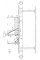
- the container filling apparatus comprises an endless belt conveyor 2 mounted on a frame l, the top part of said belt being drivable in the transport direction T.
- a rectangular box 3 Arranged above said belt 2 is a rectangular box 3 adjustable in height in such a manner that various containers, such as seed trays 4, can be passed underneath box 3 on belt 2 with some clearance.
- a reservoir 7 for filling material 8 is partitioned off by an inclined transverse wall 5 having a wall portion 6 slidable according to the double arrow S.
- a rubbing device in the form of a rotor with a vertical rotor shaft 9, arms l0 to which are attached flexible strips ll (see Fig. 2) and a drive motor l2.
- Fig. l shows in dotted lines a side opening l5 closable by a slide adjustable in height.
- the operation of the apparatus shown is as follows. On belt conveyor 2, first a number of seed trays 4 are successively, and in closed-up formation, pushed underneath box 3 until the foremost trays 4 are underneath the bottom opening of the reservoir 7. Then, filling material is deposited into reservoir 7, whereby the cavities l6 in the seed trays 4 located underneath the bottom opening of reservoir 7 are automatically filled and the entire top surface of trays 4 is covered with filling material. Upon further transport of trays 4 past reservoir 7, a layer of material remains on trays 4, whose thickness depends on the level of the lower edge of the transverse wall portion 6. This material is rubbed for the most part into the seed tray cavities l6 by the rotor 9, l0, ll operative behind the transverse wall 5, 6.
- the quantity of filling material per cavity l6 can thus be controlled in a simple manner by adjusting the height of the transverse wall portion 6, with the rotor speed being a further possibility of control. According as the flexible strips ll on the rotor arms l0 brush more often along the tray surfaces, more material is rubbed into cavities l6. Any large lumps of material are thereby automatically reduced in size.
- trays 4 are cleaned by brush l3 before emerging from underneath box 3, with the inclined baffle l4 preventing brushed away material from falling back onto trays 4.
- the transverse wall portion 6 is inadvertently adjusted too high, so that so much filling material remains on trays 4 that this cannot be rubbed into the cavities l6, the excess can be discharged automatically through the lateral discharge opening l5 adjustable by a slide. Adjustment of the opening l5 provides for an additional control of the degree of filling.
Landscapes
- Life Sciences & Earth Sciences (AREA)
- Environmental Sciences (AREA)
- Basic Packing Technique (AREA)
- Sowing (AREA)
Claims (7)
- Vorrichtung zum Befüllen von Behältern (4) mit Schüttgut (8), mit einem Förderer (2) zum Zuführen wenigstens einer Reihe von hintereinander angeordneten Behältern (4) längs einer horizontalen Bahn unterhalb eines unten offenen, oberhalb des Förderers (2) angeordneten Vorratsbehälters (3) zum Befüllen des Materials, wobei wenigstens die stromabwärts gelegene Kante der unteren Öffnung des Vorratsbehälters in Transportrichtung gesehen höhenverstellbar ist und wobei hinter der unteren Öffnung des Vorratsbehälters eine Verdichtungseinrichtung (9 - 12) angeordnet ist, dadurch gekennzeichnet, daß die Verdichtungseinrichtung (9 - 12) als Schabeinrichtung mit flexiblen Streifen (11) ausgebildet ist, die auf die Behälter (4) drücken sowie über die Oberseiten der Behälter (4) streichen.
- Vorrichtung nach Anspruch 1, dadurch gekennzeichnet, daß die Schabeinrichtung (9 - 12) einen Rotor aufweist, der um eine vertikale Welle (9) drehbar ist, wobei die flexiblen Streifen (11) an Rotorarmen (10) angeordnet sind, die sich parallel zu den Behältern (2) sowie mit Abstand über diesen erstrecken.
- Vorrichtung nach Anspruch 2, dadurch gekennzeichnet, daß die Drehgeschwindigkeit des Rotors (9 - 12) veränderbar ist.
- Vorrichtung nach Anspruch 3 oder 4, dadurch gekennzeichnet, daß der Rotor (9 - 11) in einem seitlich geschlossenen Raum betätigbar ist, wobei in wenigstens einer Seitenwand eine Öffnung (15) angeordnet ist, die durch eine Schiebetür verschließbar ist.
- Vorrichtung nach einem der vorhergehenden Ansprüche, wobei stromabwärts der Schabeinrichtung (9 - 12) eine Einrichtung (13, 14) zum Entfernen des überschüssigen Befüllmaterials aus den befüllten Behältern angeordnet ist, dadurch gekennzeichnet, daß diese Einrichtung als Bürste (13) ausgebildet ist, die um eine horizontale Welle drehbar ist, welche mit einer schräggestellten Fläche (14) zusammenwirkt, die sicherstellt, daß das weggebürstete Material nicht zurück auf den Behälter (4) fallen kann.
- Vorrichtung nach einem der vorhergehenden Ansprüche, wobei der Förderer ein Förderband (2) mit einem darüber angeordneten, unten offenen Kasten (3) ist, dadurch gekennzeichnet, daß in dem Kasten (3) ein Vorratsbehälter (7) für das zu befüllende Material durch eine Querwand (5, 6) mit einer höhenverstellbaren Unterkante abgeteilt ist, und daß in dem Kasten (3) hinter der Querwand (5, 6) die Welle (9) des Rotors (10) und hinter dem Rotor (9, 10) die Bürste (13) angeordnet ist, wobei die seitliche Abführöffnung (15) in einer der Seitenwände des Kastens hinter der Querwand (5, 6) vorgesehen ist.
- Verfahren zum Befüllen von Behältern, insbesondere zum Befüllen von sogenannten Saatplatten oder Saattabletts (4) zum Bepflanzen in der Landwirtschaft sowie zur Pflanzenaufzucht mit Tonerde, Saaterde, Steinwolle oder anderen Aufzuchtmedien, wobei die Tabletts (4) flach ausgebildet sind und plattenförmige Behälter mit einer Vielzahl von nach unten schmaler werdenden Vertiefungen (16) aufweisen und wobei das zu befüllende Material derart auf die Platten (4) aufgegeben wird, daß die Vertiefungen (16) gefüllt werden, anschließend das eingefüllte Material über den Platten (4) glattgestrichen wird, so daß eine entsprechende Schicht auf den Platten verbleibt, und schließlich das Material der Schicht in die Vertiefungen (16) gepreßt wird, dadurch gekennzeichnet, daß das überstehende Material dadurch in die Vertiefungen (16) gepreßt wird, daß das Material in die Vertiefungen geschabt wird.
Applications Claiming Priority (2)
| Application Number | Priority Date | Filing Date | Title |
|---|---|---|---|
| NL8601644 | 1986-06-24 | ||
| NL8601644A NL8601644A (nl) | 1986-06-24 | 1986-06-24 | Houdervulling. |
Publications (2)
| Publication Number | Publication Date |
|---|---|
| EP0251400A1 EP0251400A1 (de) | 1988-01-07 |
| EP0251400B1 true EP0251400B1 (de) | 1991-09-04 |
Family
ID=19848215
Family Applications (1)
| Application Number | Title | Priority Date | Filing Date |
|---|---|---|---|
| EP19870201188 Expired EP0251400B1 (de) | 1986-06-24 | 1987-06-23 | Behältereinfüllvorrichtung |
Country Status (4)
| Country | Link |
|---|---|
| EP (1) | EP0251400B1 (de) |
| DE (1) | DE3772647D1 (de) |
| ES (1) | ES2025138B3 (de) |
| NL (1) | NL8601644A (de) |
Families Citing this family (7)
| Publication number | Priority date | Publication date | Assignee | Title |
|---|---|---|---|---|
| NL193353C (nl) * | 1989-08-31 | 1999-08-03 | Visser S Gravendeel Holding | Tray-vulmachine. |
| NL193354C (nl) * | 1992-05-20 | 1999-08-03 | Visser S Gravendeel Holding | Trayvulinrichting. |
| US5315810A (en) * | 1992-06-11 | 1994-05-31 | Eaton Jay S | Method for filling seed trays |
| NL1004565C2 (nl) * | 1996-11-19 | 1998-05-20 | Potveer Bv | Werkwijze en inrichting voor het vullen van houders met los materiaal. |
| AT1805U1 (de) * | 1996-12-02 | 1997-12-29 | Blumi Blumenerdenerzeugung Ges | Verfahren zur bereitstellung von blumenerde sowie einrichtung zur durchführung dieses verfahrens |
| FR2855935B1 (fr) * | 2003-06-12 | 2005-08-05 | Jean Charles Taugourdeau | Procede de remlissage de pots a l'aide d'une matiere de remplissage telle que de la terre, du terreau, du sable et autres |
| NL2010403C2 (en) * | 2013-03-06 | 2014-09-10 | Nobels Machf B V | Soil filling machine for depositing soil in pots for plants. |
Family Cites Families (3)
| Publication number | Priority date | Publication date | Assignee | Title |
|---|---|---|---|---|
| US3571971A (en) * | 1968-05-23 | 1971-03-23 | Hoyer Foundry And Machine Co | Automatic flat filler and dibbler |
| NL7107992A (de) * | 1971-06-10 | 1972-12-12 | ||
| DE8614643U1 (de) * | 1986-05-30 | 1986-10-16 | Engling, Ernst, 2081 Bilsen | Vorrichtung zum Einfüllen von Erdsubstrat in Pflanzbehälter |
-
1986
- 1986-06-24 NL NL8601644A patent/NL8601644A/nl not_active Application Discontinuation
-
1987
- 1987-06-23 ES ES87201188T patent/ES2025138B3/es not_active Expired - Lifetime
- 1987-06-23 DE DE8787201188T patent/DE3772647D1/de not_active Expired - Lifetime
- 1987-06-23 EP EP19870201188 patent/EP0251400B1/de not_active Expired
Also Published As
| Publication number | Publication date |
|---|---|
| NL8601644A (nl) | 1988-01-18 |
| EP0251400A1 (de) | 1988-01-07 |
| DE3772647D1 (de) | 1991-10-10 |
| ES2025138B3 (es) | 1992-03-16 |
Similar Documents
| Publication | Publication Date | Title |
|---|---|---|
| US4542687A (en) | Green peanut destemmer and washer | |
| EP0251400B1 (de) | Behältereinfüllvorrichtung | |
| US5401281A (en) | Process and installation for the industrial production of plants in soil-free cultivation | |
| US2771709A (en) | Planting and equipment therefor | |
| US4010778A (en) | Automatic seed planting machine and method for planting seeds in planters | |
| KR102506483B1 (ko) | 컨테이너 조경수용 묘목 식재시스템 | |
| US4106415A (en) | Plant-setting machine | |
| US3433181A (en) | Piemaking machine | |
| CN118058037B (zh) | 大蒜播种机用取种装置 | |
| US5315810A (en) | Method for filling seed trays | |
| KR100227322B1 (ko) | 종이통 집합화분에의 모판흙 충전장치 | |
| CN210445115U (zh) | 一种带平整功能的培养基均匀布料装置 | |
| EP0039691B1 (de) | Verfahren und vorrichtung zum setzen von pflanzen | |
| JPS63313506A (ja) | 播種装置 | |
| CN221729092U (zh) | 一种穴盘注料装置 | |
| JPH0433697Y2 (de) | ||
| FR2557762A1 (fr) | Dispositif de remplissage automatique avec de la terre des capacites de culture. | |
| JP3406670B2 (ja) | ポットシート用土供給装置 | |
| JP3674920B2 (ja) | 田植機供給苗用播種機 | |
| CN213718624U (zh) | 一种蔬菜播种装置 | |
| EP0005982A2 (de) | Maschine zum Füllen eines ausgehobenen Grabens im Grund | |
| BR102020001427B1 (pt) | Equipamento para enchimento de bandejas para mudas em geral | |
| CN118216346A (zh) | 豆芽播种生产线 | |
| SU1161000A1 (ru) | Способ брикетировани корневой системы саженцев и устройство дл его осуществлени | |
| JPH05966B2 (de) |
Legal Events
| Date | Code | Title | Description |
|---|---|---|---|
| PUAI | Public reference made under article 153(3) epc to a published international application that has entered the european phase |
Free format text: ORIGINAL CODE: 0009012 |
|
| AK | Designated contracting states |
Kind code of ref document: A1 Designated state(s): BE CH DE ES FR GB IT LI NL |
|
| 17P | Request for examination filed |
Effective date: 19880629 |
|
| 17Q | First examination report despatched |
Effective date: 19900710 |
|
| GRAA | (expected) grant |
Free format text: ORIGINAL CODE: 0009210 |
|
| AK | Designated contracting states |
Kind code of ref document: B1 Designated state(s): BE CH DE ES FR GB IT LI NL |
|
| REF | Corresponds to: |
Ref document number: 3772647 Country of ref document: DE Date of ref document: 19911010 |
|
| ET | Fr: translation filed | ||
| ITF | It: translation for a ep patent filed | ||
| REG | Reference to a national code |
Ref country code: ES Ref legal event code: FG2A Ref document number: 2025138 Country of ref document: ES Kind code of ref document: B3 |
|
| PLBE | No opposition filed within time limit |
Free format text: ORIGINAL CODE: 0009261 |
|
| STAA | Information on the status of an ep patent application or granted ep patent |
Free format text: STATUS: NO OPPOSITION FILED WITHIN TIME LIMIT |
|
| 26N | No opposition filed | ||
| PGFP | Annual fee paid to national office [announced via postgrant information from national office to epo] |
Ref country code: ES Payment date: 19930513 Year of fee payment: 7 |
|
| PGFP | Annual fee paid to national office [announced via postgrant information from national office to epo] |
Ref country code: FR Payment date: 19930514 Year of fee payment: 7 |
|
| PGFP | Annual fee paid to national office [announced via postgrant information from national office to epo] |
Ref country code: GB Payment date: 19930611 Year of fee payment: 7 |
|
| PGFP | Annual fee paid to national office [announced via postgrant information from national office to epo] |
Ref country code: DE Payment date: 19930621 Year of fee payment: 7 |
|
| PGFP | Annual fee paid to national office [announced via postgrant information from national office to epo] |
Ref country code: NL Payment date: 19930630 Year of fee payment: 7 |
|
| PGFP | Annual fee paid to national office [announced via postgrant information from national office to epo] |
Ref country code: BE Payment date: 19930701 Year of fee payment: 7 |
|
| PGFP | Annual fee paid to national office [announced via postgrant information from national office to epo] |
Ref country code: CH Payment date: 19930830 Year of fee payment: 7 |
|
| PG25 | Lapsed in a contracting state [announced via postgrant information from national office to epo] |
Ref country code: GB Effective date: 19940623 |
|
| PG25 | Lapsed in a contracting state [announced via postgrant information from national office to epo] |
Ref country code: ES Free format text: LAPSE BECAUSE OF THE APPLICANT RENOUNCES Effective date: 19940624 |
|
| PG25 | Lapsed in a contracting state [announced via postgrant information from national office to epo] |
Ref country code: LI Effective date: 19940630 Ref country code: CH Effective date: 19940630 Ref country code: BE Effective date: 19940630 |
|
| BERE | Be: lapsed |
Owner name: MACHINEFABRIEK GEBR. FLIER B.V. Effective date: 19940630 |
|
| PG25 | Lapsed in a contracting state [announced via postgrant information from national office to epo] |
Ref country code: NL Effective date: 19950101 |
|
| NLV4 | Nl: lapsed or anulled due to non-payment of the annual fee | ||
| GBPC | Gb: european patent ceased through non-payment of renewal fee |
Effective date: 19940623 |
|
| PG25 | Lapsed in a contracting state [announced via postgrant information from national office to epo] |
Ref country code: FR Effective date: 19950228 |
|
| REG | Reference to a national code |
Ref country code: CH Ref legal event code: PL |
|
| PG25 | Lapsed in a contracting state [announced via postgrant information from national office to epo] |
Ref country code: DE Effective date: 19950301 |
|
| REG | Reference to a national code |
Ref country code: FR Ref legal event code: ST |
|
| REG | Reference to a national code |
Ref country code: ES Ref legal event code: FD2A Effective date: 19991007 |
|
| PG25 | Lapsed in a contracting state [announced via postgrant information from national office to epo] |
Ref country code: IT Free format text: LAPSE BECAUSE OF NON-PAYMENT OF DUE FEES Effective date: 20050623 |