EP0250822A2 - Bildröhre mit Ablenkeinheit - Google Patents
Bildröhre mit Ablenkeinheit Download PDFInfo
- Publication number
- EP0250822A2 EP0250822A2 EP87107142A EP87107142A EP0250822A2 EP 0250822 A2 EP0250822 A2 EP 0250822A2 EP 87107142 A EP87107142 A EP 87107142A EP 87107142 A EP87107142 A EP 87107142A EP 0250822 A2 EP0250822 A2 EP 0250822A2
- Authority
- EP
- European Patent Office
- Prior art keywords
- picture tube
- deflection unit
- ring
- neck
- thermoplastic material
- Prior art date
- Legal status (The legal status is an assumption and is not a legal conclusion. Google has not performed a legal analysis and makes no representation as to the accuracy of the status listed.)
- Granted
Links
- 239000012815 thermoplastic material Substances 0.000 claims abstract description 15
- 238000003466 welding Methods 0.000 claims abstract description 8
- 239000000853 adhesive Substances 0.000 claims description 12
- 230000001070 adhesive effect Effects 0.000 claims description 12
- 239000002390 adhesive tape Substances 0.000 claims description 3
- 238000000034 method Methods 0.000 abstract description 4
- 229920001169 thermoplastic Polymers 0.000 abstract description 3
- 239000004416 thermosoftening plastic Substances 0.000 abstract description 3
- 238000004026 adhesive bonding Methods 0.000 description 5
- 238000002844 melting Methods 0.000 description 4
- 230000008018 melting Effects 0.000 description 4
- 239000004831 Hot glue Substances 0.000 description 3
- 238000013459 approach Methods 0.000 description 3
- 238000010438 heat treatment Methods 0.000 description 3
- 238000006073 displacement reaction Methods 0.000 description 2
- 230000000694 effects Effects 0.000 description 2
- 239000012790 adhesive layer Substances 0.000 description 1
- 230000002411 adverse Effects 0.000 description 1
- 230000015572 biosynthetic process Effects 0.000 description 1
- 238000005336 cracking Methods 0.000 description 1
- 238000013461 design Methods 0.000 description 1
- 238000011161 development Methods 0.000 description 1
- 230000018109 developmental process Effects 0.000 description 1
- 238000005755 formation reaction Methods 0.000 description 1
- 239000000463 material Substances 0.000 description 1
- 239000004033 plastic Substances 0.000 description 1
- 238000003825 pressing Methods 0.000 description 1
- 238000012545 processing Methods 0.000 description 1
- 238000007788 roughening Methods 0.000 description 1
- 230000002277 temperature effect Effects 0.000 description 1
Images
Classifications
-
- H—ELECTRICITY
- H01—ELECTRIC ELEMENTS
- H01J—ELECTRIC DISCHARGE TUBES OR DISCHARGE LAMPS
- H01J29/00—Details of cathode-ray tubes or of electron-beam tubes of the types covered by group H01J31/00
- H01J29/46—Arrangements of electrodes and associated parts for generating or controlling the ray or beam, e.g. electron-optical arrangement
- H01J29/82—Mounting, supporting, spacing, or insulating electron-optical or ion-optical arrangements
- H01J29/823—Mounting, supporting, spacing, or insulating electron-optical or ion-optical arrangements around the neck of the tube
- H01J29/826—Deflection arrangements
Definitions
- the invention relates to a picture tube with a deflection unit fastened thereon according to the preamble of claim 1.
- the deflection unit for a picture tube sits on the picture tube neck and lies against the cone of the picture tube. After the deflection unit has been mounted on the picture tube, it must be precisely adjusted with respect to the picture tube so that a perfect image is obtained. Then the deflection unit must be attached to the picture tube so that it can no longer move. When attaching the deflection unit to the picture tube, the pressure and the temperature must not be too high or too high, as this can damage the picture tube.
- the deflection unit on the picture tube can be mechanical or attached by gluing.
- the deflection unit can be attached to the picture tube with a clamp that can be tightened by a screw. When the screw is loosened, the deflection unit can be moved on the picture tube neck and after adjustment, the deflection unit can be fixed by tightening the screw.
- excessive pressure must not be applied to avoid cracking of the picture tube neck.
- a suitable adhesive must be introduced between the deflection unit and the picture tube. This is difficult and usually requires special channels to apply the adhesive.
- a cold-curing adhesive has the advantage that the temperature effect on the picture tube is low, but the disadvantage that on the one hand the adjustment process must be completed before the adhesive hardens, and on the other hand the deflection unit must be held in position until the adhesive has hardened.
- the softening temperature When using a heat-softening adhesive, the softening temperature must not be too high to avoid impairing the picture tube. On the other hand, when the picture tube is in operation, it must not heat up so much that the adhesive softens and the deflection unit shifts.
- thermoplastic material are to be cemented between the deflection unit and the picture tube, which connect the two parts to one another.
- a hot glue with a melting temperature of around 150 ° C is used for this.
- the picture tube must be kept at 50 ° C when applying the hot glue.
- the deflection unit must also be provided with corresponding channels into which the hot glue can be introduced.
- DE-OS 25 51 288 it is also known to attach a deflection unit on a picture tube in such a way that a ring is first attached to the cone of the picture tube by means of an adhesive, which has four hollow approaches.
- the deflection unit is provided on its circumference with radially outwardly projecting flags and is used with these in hollow formations of a second annular plastic part and both parts are then placed together on the pins of the first, glued-on annular part and connected to one another by filling in an adhesive.
- This embodiment requires several complicatedly shaped parts that have to be connected to one another.
- the object of the invention is to fasten a deflection unit on a picture tube with a few simple parts quickly and safely.
- a ring made of thermoplastic material is first attached to the picture tube neck.
- the attachment can be done by gluing, for example by means of a so-called double-sided adhesive tape.
- a cold-curing adhesive can also be used for this, since the fastening of the ring is independent of the adjustment of the deflection unit.
- the deflection unit itself has a tubular extension formed on its coil former from the same thermoplastic material from which the ring attached to the tube neck is made. It is preferably an amorphous or partially crystalline thermoplastic.
- the deflection unit is now pushed over the tube neck until the tubular extension comes to rest on the ring attached to the tube neck.
- the deflection unit can now be moved in the longitudinal direction in an adjusting device and also rotated until it has reached its optimal position. Now, by means of a short welding process, preferably by spot welding, the ring sitting on the tube neck is welded to the tubular extension of the coil body of the deflection unit, as a result of which the deflection unit is immediately firmly seated relative to the picture tube.
- the deflection unit 4 is partially seated on the picture tube neck 2 and partially abuts the picture tube cone 3.
- the coil body 5 of the deflection unit 4 has a tubular extension 6, which consists of thermoplastic material.
- the material is preferably an amorphous or partially crystalline thermoplastic.
- a ring 7 made of the same thermoplastic material as the extension 6 is attached to the picture tube neck 2, preferably by gluing.
- the ring 7 made of thermoplastic material is attached to the tube neck 2 by gluing.
- a cold-curing adhesive can be used, for example, or a double-sided adhesive tape.
- the deflection unit 4 is then pushed onto the picture tube in such a way that the tubular extension 6 of the bobbin 5 of the deflection unit 4 comes to rest on the ring 7.
- the deflection unit 4 is displaced in the longitudinal direction in a suitable adjusting device or rotated about its axis with respect to the picture tube until its optimal position is reached.
- the approach 6 are connected to the ring 7 by a short welding process, so that the deflection unit 4 is now fixed in its position with respect to the picture tube 1.
- the tubular extension 6 can be slotted in the direction of the tube axis.
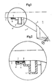
- Fig. 2 which shows an enlarged section of the parts shown in circle A of Fig. 1, the adhesive layer 8 can also be seen, with which the ring 7 is attached to the picture tube neck 2 and a weld 9, with which the approach 6 and the ring 7 are interconnected.
- thermoplastic material from which the tubular extension 6 and the ring 7 are made can have a relatively high melting point because only a brief heating is required to weld the two parts, and this does not have any adverse effect on the picture tube.
- the welding at 9 of FIG. 2 can be achieved, for example, by pressing in a heated stamp at several points on the circumference.
- the ring 7 preferably has a surface which is curved in the direction of the tube axis or the tube neck. This can be seen particularly well from FIG. 2.
- the deflection unit can be moved in all directions, and after the two parts made of thermoplastic material have been welded, the picture tube and deflection unit can be taken out of the adjustment holder immediately, since the thermoplastic material quickly solidifies due to its high melting point. Nevertheless, there is no impermissibly high thermal effect on the picture tube, because only a brief and local heating is necessary and the welding takes place on the surface of the ring 7 facing away from the picture tube.
- thermoplastic material As a result of the relatively high melting point of the thermoplastic material, there is no fear of displacement of the deflection unit due to heating during the operation of the picture tube.
Landscapes
- Vessels, Lead-In Wires, Accessory Apparatuses For Cathode-Ray Tubes (AREA)
- Lining Or Joining Of Plastics Or The Like (AREA)
Abstract
Description
- Die Erfindung bezieht sich auf eine Bildröhre mit darauf befestigter Ablenkeinheit nach dem Oberbegriff des Anspruchs 1.
- Die Ablenkeinheit für eine Bildröhre sitzt auf dem Bildröhrenhals und liegt am Konus der Bildröhre an. Nach dem Aufbringen der Ablenkeinheit auf die Bildröhre muß sie bezüglich der Bildröhre genau justiert werden, damit ein einwandfreies Bild erhalten wird. Danach muß die Ablenkeinheit an der Bildröhre so befestigt werden, daß sie sich nicht mehr verschieben kann. Bei der Befestigung der Ablenkeinheit auf der Bildröhre darf kein zu hoher Druck und keine zu hohe Temperatur zur Einwirkung auf die Bildröhre kommen, da dies zu einer Beschädigung der Bildröhre führen kann.
- Wie es beispielsweise in der DE-OS 24 08 673 beschrieben ist, kann die Ablenkeinheit auf der Bildröhre mechanisch oder durch Kleben befestigt werden. So kann die Ablenkeinheit auf der Bildröhre beispielsweise mit einer durch eine Schraube anziehbaren Schelle befestigt werden. Bei gelockerter Schraube kann die Ablenkeinheit auf dem Bildröhrenhals verschoben werden und nach dem Justieren kann durch Anziehen der Schraube die Ablenkeinheit festgesetzt werden. Allerdings darf dabei kein zu hoher Druck ausgeübt werden, damit ein Springen des Bildröhrenhalses vermieden wird. Wenn die Ablenkeinheit auf dem Bildröhrenhals durch Kleben befestigt wird, so muß ein geeigneter Kleber zwischen Ablenkeinheit und Bildröhre eingebracht werden. Dies ist schwierig und erfordert meist besondere Kanäle, um den Kleber einzubringen. Ein kalthärtender Kleber hat zwar den Vorteil, daß die Temperatureinwirkung auf die Bildröhre gering ist, aber den Nachteil, daß einerseits der Justiervorgang bis zum Erhärten des Klebers beendet sein muß, andererseits die Ablenkeinheit bis zum Erhärten des Klebers in ihrer Lage gehalten werden muß.
- Bei Verwendung eines durch Wärme erweichbaren Klebers darf die Erweichungstemperatur nicht zu hoch liegen, damit eine Beeinträchtigung der Bildröhre vermieden wird. Andererseits darf sich beim Betrieb der Bildröhre diese nicht so weit erhitzen, daß der Kleber erweicht und sich die Ablenkeinheit verschiebt.
- Da mit allen diesen Mitteln offenbar keine befriedigende Befestigung der Ablenkeinheit auf der Bildröhre erzielt werden kann, wird in der DE-OS 24 08 673 vorgeschlagen, die Bildröhre an ihrem Konus mit Rippen oder Aufrauhungen zu versehen, durch die eine Verschiebung der justierten Ablenkeinheit vermieden werden soll. Dies bedingt aber zusätzlich eine besondere Ausbildung des Bildröhrenkörpers bzw. eine zusätzliche Bearbeitung desselben.
- Nach der DE-AS 23 42 052 sollen zwischen Ablenkeinheit und Bildröhre einzelne, in Längsrichtung verlaufende Streifen aus thermoplastischem Material eingekittet werden, die beide Teile miteinander verbinden. Hierzu wird ein Heißkleber mit einer Schmelztemperatur von etwa 150°C verwendet. Die Bildröhre muß beim Einbringen des Heißklebers aber auf 50°C gehalten werden. Auch muß die Ablenkeinheit mit entsprechenden Kanälen versehen sein, in die der Heißkleber eingebracht werden kann.
- Aus der DE-OS 25 51 288 ist es weiter bekannt, eine Ablenkeinheit auf einer Bildröhre in der Weise zu befestigen, daß zunächst auf dem Konus der Bildröhre mittels eines Klebers ein Ring befestigt wird, der vier hohle Ansätze besitzt. Die Ablenkeinheit ist auf ihrem Umfang mit radial nach außen stehenden Fahnen versehen und wird mit diesen in hohle Ausformungen eines zweiten ringförmigen Kunststoffteils eingesetzt und beide Teile werden dann zusammen auf die Zapfen des ersten, aufgeklebten ringförmigen Teils aufgesetzt und durch Einfüllen eines Klebers miteinander verbunden. Diese Ausführungsform bedingt mehrere kompliziert geformte Teile, die miteinander verbunden werden müssen.
- Aufgabe der Erfindung ist es, eine Ablenkeinheit auf einer Bildröhre mit wenigen einfachen Teilen schnell und sicher zu befestigen.
- Diese Aufgabe wird durch die im Anspruch 1 angegebenen Maßnahmen gelöst. Vorteilhafte Weiterbildungen der Erfindung gehen aus den Unteransprüchen 2 bis 6 hervor.
- Gemäß der Erfindung wird auf dem Bildröhrenhals zunächst ein Ring aus thermoplastischem Material befestigt. Die Befestigung kann durch Kleben erfolgen, beispielsweise mittels eines sogenannten doppelseitigen Klebebandes. Es kann hierzu auch ein kalthärtender Kleber verwendet werden, da die Befestigung des Ringes unabhängig von der Justierung der Ablenkeinheit ist.
- Die Ablenkeinheit selbst hat einen an ihrem Spulenkörper angeformten rohrförmigen Ansatz aus dem gleichen thermoplastischen Material, aus dem der auf dem Röhrenhals befestigte Ring besteht. Es handelt sich vorzugsweise um einen amorphen oder teilkristallinen Thermoplasten. Die Ablenkeinheit wird nun über den Röhrenhals geschoben, bis der rohrförmige Ansatz über dem auf dem Röhrenhals befestigten Ring zu liegen kommt. Die Ablenkeinheit kann nun in einer Justiervorrichtung in Längsrichtung verschoben und auch gedreht werden, bis sie ihre optimale Lage eingenommen hat. Nun wird durch einen kurzen Schweißvorgang, vorzugsweise durch Punktschweißen, der auf dem Röhrenhals sitzende Ring mit dem rohrförmigen Ansatz des Spulenkörpers der Ablenkeinheit verschweißt, wodurch sofort ein fester Sitz der Ablenkeinheit gegenüber der Bildröhre erzielt ist.
- Die Erfindung wird nun anhand von einem in den Figuren gezeigten Ausführungsbeispiel näher beschrieben. Es zeigen:
- Fig. 1 schematisch Teile von Hals und Konus einer Bildröhre sowie die darauf angeordnete Ablenkeinheit, teilweise im Schnitt und
- Fig. 2 zur Verdeutlichung der Einzelheiten eine vergrößerte Darstellung der im Kreis A von Fig. 1 dargestellten Teile.
- Von der Bildröhre 1 sind in Fig. 1 nur Teile vom Bildröhrenhals 2 und vom Bildröhrenkonus 3 dargestellt. Die Ablenkeinheit 4 sitzt teilweise auf dem Bildröhrenhals 2 und liegt teilweise am Bildröhrenkonus 3 an. Der Spulenkörper 5 der Ablenkeinheit 4 hat einen rohrförmigen Ansatz 6, der aus thermopolastischem Material besteht. Bei dem Material handelt es sich vorzugsweise um einen amorphen oder teilkristallinen Thermoplasten. Unter diesem ist auf dem Bildröhrenhals 2 ein Ring 7 aus dem gleichen thermoplastischen Material wie der Ansatz 6 befestigt, und zwar vorzugsweise durch Kleben.
- Es wird also zuerst der Ring 7 aus thermoplastischem Matrial auf dem Röhrenhals 2 durch Kleben befestigt. Hierzu kann beispielsweise ein kalthärtender Kleber verwendet werden oder auch ein dopelseitiges Klebeband. Die Ablenkeinheit 4 wird dann auf die Bildröhre so aufgeschoben, daß der rohrförmige Ansatz 6 des Spulenkörpers 5 der Ablenkeinheit 4 auf dem Ring 7 zu liegen kommt. Nun wird in einer geeigneten Justiervorrichtung die Ablenkeinheit 4 in Längsrichtung verschoben oder um ihre Achse bezüglich der Bildröhre gedreht, bis ihre optimale Lage erreicht ist. Dann werden durch einen kurzen Schweißprozeß der Ansatz 6 mit dem Ring 7 verbunden, so daß die Ablenkeinheit 4 nunmehr in ihrer Lage bezüglich der Bildröhre 1 festgelegt ist. Zum Toleranzausgleich kann der rohrförmige Ansatz 6 in Richtung der Rohrachse geschlitzt sein.
- Aus Fig. 2, die einen vergrößerten Ausschnitt der im Kreis A von Fig. 1 dargestellten Teile zeigt, ist zusätzlich die Klebschicht 8 erkennbar, mit der der Ring 7 auf dem Bildröhrenhals 2 befestigt ist und eine Schweißstelle 9, mit der der Ansatz 6 und der Ring 7 miteinander verbunden sind.
- Das thermoplastische Material, aus dem der rohrförmige Ansatz 6 und der Ring 7 bestehen, kann einen verhältnismäßig hohen Schmelzpunkt haben, weil zum Verschweißen der beiden Teile nur eine kurzzeitige Erwärmung erforderlich ist, die keinen nachteiligen Einfluß auf die Bildröhre ausübt. Das Verschweißen bei 9 von Fig. 2 kann beispielsweise durch Eindrücken eines erhitzten Stempels an mehreren Stellen des Umfanges erzielt werden.
- Um auch ein Justieren der Ablenkeinheit durch Kippen bezüglich der Achse der Bildröhre zu ermöglichen, hat der Ring 7 vorzugsweise eine in Richtung der Röhrenachse bzw. des Röhrenhalses gewölbte Oberfläche. Dies ist insbesondere aus Fig. 2 gut ersichtlich.
- Wie aus den Figuren erkennbar ist, werden bei der Erfindung nur wenige und einfach aufgebaute Teile zur Befestigung der Ablenkeinheit auf der Bildröhre benötigt. Zum Justieren läßt sich die Ablenkeinheit nach allen Richtungen hin bewegen und nach dem Verschweißen der beiden Teile aus thermoplastischem Material können Bildröhre und Ablenkeinheit gleich aus der Justierhalterung genommen werden, da das thermoplastische Material infolge seines hohen Schmelzpunktes sich sehr schnell verfestigt. Trotzdem ist keine unzulässig hohe thermische Einwirkung auf die Bildröhre vorhanden, da nur eine kurzzeitige und örtliche Erwärmung erforderlich ist und die Verschweißung auf der von der Bildröhre abgewandten Oberfläche des Ringes 7 stattfindet.
- Infolge des verhältnismäßig hohen Schmelzpunktes des thermoplastischen Materials ist eine Verschiebung der Ablenkeinheit durch Erwärmung während des Betriebes der Bildröhre nicht zu befürchten.
Claims (6)
Applications Claiming Priority (2)
| Application Number | Priority Date | Filing Date | Title |
|---|---|---|---|
| DE3621363 | 1986-06-26 | ||
| DE19863621363 DE3621363A1 (de) | 1986-06-26 | 1986-06-26 | Bildroehre mit ablenkeinheit |
Publications (3)
| Publication Number | Publication Date |
|---|---|
| EP0250822A2 true EP0250822A2 (de) | 1988-01-07 |
| EP0250822A3 EP0250822A3 (en) | 1990-04-04 |
| EP0250822B1 EP0250822B1 (de) | 1993-08-04 |
Family
ID=6303718
Family Applications (1)
| Application Number | Title | Priority Date | Filing Date |
|---|---|---|---|
| EP87107142A Expired - Lifetime EP0250822B1 (de) | 1986-06-26 | 1987-05-18 | Bildröhre mit Ablenkeinheit |
Country Status (3)
| Country | Link |
|---|---|
| EP (1) | EP0250822B1 (de) |
| JP (1) | JPS636733A (de) |
| DE (2) | DE3621363A1 (de) |
Cited By (1)
| Publication number | Priority date | Publication date | Assignee | Title |
|---|---|---|---|---|
| EP0521555A1 (de) * | 1991-07-02 | 1993-01-07 | Koninklijke Philips Electronics N.V. | Bildwiedergaberöhre mit darauf angeordneter Ablenkeinheit |
Family Cites Families (4)
| Publication number | Priority date | Publication date | Assignee | Title |
|---|---|---|---|---|
| US3663751A (en) * | 1970-04-16 | 1972-05-16 | Westinghouse Electric Corp | Potted elctrical component assembly |
| JPS5325232B2 (de) * | 1972-04-10 | 1978-07-25 | ||
| JPS5093036A (de) * | 1973-12-17 | 1975-07-24 | ||
| DE2650907A1 (de) * | 1976-11-06 | 1978-05-18 | Licentia Gmbh | Fernsehbildroehre mit einer daran befestigten ablenkeinheit |
-
1986
- 1986-06-26 DE DE19863621363 patent/DE3621363A1/de not_active Withdrawn
-
1987
- 1987-05-18 EP EP87107142A patent/EP0250822B1/de not_active Expired - Lifetime
- 1987-05-18 DE DE8787107142T patent/DE3786847D1/de not_active Expired - Fee Related
- 1987-06-24 JP JP62155632A patent/JPS636733A/ja active Pending
Cited By (1)
| Publication number | Priority date | Publication date | Assignee | Title |
|---|---|---|---|---|
| EP0521555A1 (de) * | 1991-07-02 | 1993-01-07 | Koninklijke Philips Electronics N.V. | Bildwiedergaberöhre mit darauf angeordneter Ablenkeinheit |
Also Published As
| Publication number | Publication date |
|---|---|
| DE3786847D1 (de) | 1993-09-09 |
| EP0250822B1 (de) | 1993-08-04 |
| EP0250822A3 (en) | 1990-04-04 |
| JPS636733A (ja) | 1988-01-12 |
| DE3621363A1 (de) | 1988-01-14 |
Similar Documents
| Publication | Publication Date | Title |
|---|---|---|
| DE3881120T2 (de) | Schaedelbohrer, versehen mit einer verbesserten befestigungshuelse. | |
| DE102007046376B4 (de) | Verschweißter Harzkörper und Verfahren zu dessen Herstellung | |
| DE3330874A1 (de) | Werkstuecktraeger und verfahren zum aufspannen eines werkstueckes | |
| DE9290143U1 (de) | Angioplastie-Ballonkatheter und Vorrichtung zu deren Herstellung | |
| DE4013162C2 (de) | ||
| EP0433925A2 (de) | Hydraulisches Spannelement | |
| DE3812353C2 (de) | ||
| EP0745779A1 (de) | Verfahren zum Befestigen einer aus nicht schweissbarem Material bestehenden Achslagerbuchse in einem Loch einer metallischen Trägerplatte. | |
| EP0973014B1 (de) | Winkelmessvorrichtung und Verfahren zur Montage einer Winkelmessvorrichtung | |
| EP0250822B1 (de) | Bildröhre mit Ablenkeinheit | |
| DE2243492A1 (de) | Vorrichtung zum abschleifen der oberflaeche einer zwei roehrenfoermige teilstuecke verbindenden schweissnaht | |
| DE19819054B4 (de) | Verfahren und Vorrichtung zur Montage und Justierung von Bauteilen auf einer Befestigungsunterlage | |
| DE19813766A1 (de) | Verfahren und Vorrichtung zum Vorbereiten und Bilden einer Fügeverbindung | |
| DE4437989A1 (de) | Verfahren zum Herstellen von Gelenkscheiben | |
| EP1357020B1 (de) | Klebeverbindung | |
| DE69202426T2 (de) | Ablenkeinheit und Herstellungsverfahren. | |
| DE3610313C2 (de) | ||
| DE3907506A1 (de) | Verfahren zur verbindung eines duesenrohres einer tintenstrahlduese mit einem druckempfindlichen element | |
| EP0170956A2 (de) | Verfahren zum Aufspannen von biegsamen Druckplatten auf den Formzylinder einer Druckmaschine | |
| EP0611643A1 (de) | Verfahren zur Herstellung punktueller oder kleinflächiger Schweissverbindungen zwischen wenigstens zwei zumindest im Schweissbereich aneinander anliegenden oder angenäherten Lagen thermoplastischer Kunststoffe | |
| WO1995024355A1 (de) | Fadenbremsvorrichtung und fadenspeicher- und i-liefervorrichtung | |
| DE2655960C3 (de) | Einrichtung zum Befestigen einer Ablenkeinheit am Kolben einer Fernsehbildröhre | |
| DE2413678C3 (de) | Bremskraftverstärker für eine Fahrzeug-Bremsanlage | |
| EP4339467B1 (de) | Blindniet, sowie system und verfahren zum herstellen von abgedichteten blindnietverbindungen | |
| WO2003066273A1 (de) | Spannvorrichtung und verfahren zum laserschweissen beschichteter bleche |
Legal Events
| Date | Code | Title | Description |
|---|---|---|---|
| PUAI | Public reference made under article 153(3) epc to a published international application that has entered the european phase |
Free format text: ORIGINAL CODE: 0009012 |
|
| AK | Designated contracting states |
Kind code of ref document: A2 Designated state(s): DE FR GB IT NL |
|
| RAP1 | Party data changed (applicant data changed or rights of an application transferred) |
Owner name: NOKIA GRAETZ GESELLSCHAFT MIT BESCHRAENKTER HAFTUN |
|
| RAP1 | Party data changed (applicant data changed or rights of an application transferred) |
Owner name: NOKIA UNTERHALTUNGSELEKTRONIK (DEUTSCHLAND) GMBH |
|
| PUAL | Search report despatched |
Free format text: ORIGINAL CODE: 0009013 |
|
| AK | Designated contracting states |
Kind code of ref document: A3 Designated state(s): DE FR GB IT NL |
|
| RHK1 | Main classification (correction) |
Ipc: H01J 29/82 |
|
| 17P | Request for examination filed |
Effective date: 19900319 |
|
| RAP1 | Party data changed (applicant data changed or rights of an application transferred) |
Owner name: NOKIA (DEUTSCHLAND) GMBH |
|
| 17Q | First examination report despatched |
Effective date: 19920518 |
|
| GRAA | (expected) grant |
Free format text: ORIGINAL CODE: 0009210 |
|
| AK | Designated contracting states |
Kind code of ref document: B1 Designated state(s): DE FR GB IT NL |
|
| GBT | Gb: translation of ep patent filed (gb section 77(6)(a)/1977) |
Effective date: 19930803 |
|
| ITF | It: translation for a ep patent filed | ||
| REF | Corresponds to: |
Ref document number: 3786847 Country of ref document: DE Date of ref document: 19930909 |
|
| ET | Fr: translation filed | ||
| PGFP | Annual fee paid to national office [announced via postgrant information from national office to epo] |
Ref country code: GB Payment date: 19940511 Year of fee payment: 8 |
|
| PGFP | Annual fee paid to national office [announced via postgrant information from national office to epo] |
Ref country code: FR Payment date: 19940525 Year of fee payment: 8 |
|
| PGFP | Annual fee paid to national office [announced via postgrant information from national office to epo] |
Ref country code: NL Payment date: 19940531 Year of fee payment: 8 |
|
| PLBE | No opposition filed within time limit |
Free format text: ORIGINAL CODE: 0009261 |
|
| STAA | Information on the status of an ep patent application or granted ep patent |
Free format text: STATUS: NO OPPOSITION FILED WITHIN TIME LIMIT |
|
| PGFP | Annual fee paid to national office [announced via postgrant information from national office to epo] |
Ref country code: DE Payment date: 19940712 Year of fee payment: 8 |
|
| 26N | No opposition filed | ||
| PG25 | Lapsed in a contracting state [announced via postgrant information from national office to epo] |
Ref country code: GB Effective date: 19950518 |
|
| PG25 | Lapsed in a contracting state [announced via postgrant information from national office to epo] |
Ref country code: NL Effective date: 19951201 |
|
| GBPC | Gb: european patent ceased through non-payment of renewal fee |
Effective date: 19950518 |
|
| NLV4 | Nl: lapsed or anulled due to non-payment of the annual fee |
Effective date: 19951201 |
|
| PG25 | Lapsed in a contracting state [announced via postgrant information from national office to epo] |
Ref country code: DE Effective date: 19960201 |
|
| PG25 | Lapsed in a contracting state [announced via postgrant information from national office to epo] |
Ref country code: FR Effective date: 19960229 |
|
| REG | Reference to a national code |
Ref country code: FR Ref legal event code: ST |
|
| REG | Reference to a national code |
Ref country code: FR Ref legal event code: ST |
|
| PG25 | Lapsed in a contracting state [announced via postgrant information from national office to epo] |
Ref country code: IT Free format text: LAPSE BECAUSE OF NON-PAYMENT OF DUE FEES;WARNING: LAPSES OF ITALIAN PATENTS WITH EFFECTIVE DATE BEFORE 2007 MAY HAVE OCCURRED AT ANY TIME BEFORE 2007. THE CORRECT EFFECTIVE DATE MAY BE DIFFERENT FROM THE ONE RECORDED. Effective date: 20050518 |