EP4339467B1 - Blindniet, sowie system und verfahren zum herstellen von abgedichteten blindnietverbindungen - Google Patents
Blindniet, sowie system und verfahren zum herstellen von abgedichteten blindnietverbindungen Download PDFInfo
- Publication number
- EP4339467B1 EP4339467B1 EP22196041.2A EP22196041A EP4339467B1 EP 4339467 B1 EP4339467 B1 EP 4339467B1 EP 22196041 A EP22196041 A EP 22196041A EP 4339467 B1 EP4339467 B1 EP 4339467B1
- Authority
- EP
- European Patent Office
- Prior art keywords
- rivet
- blind rivet
- sealing ring
- tool
- support collar
- Prior art date
- Legal status (The legal status is an assumption and is not a legal conclusion. Google has not performed a legal analysis and makes no representation as to the accuracy of the status listed.)
- Active
Links
Images

Classifications
-
- F—MECHANICAL ENGINEERING; LIGHTING; HEATING; WEAPONS; BLASTING
- F16—ENGINEERING ELEMENTS AND UNITS; GENERAL MEASURES FOR PRODUCING AND MAINTAINING EFFECTIVE FUNCTIONING OF MACHINES OR INSTALLATIONS; THERMAL INSULATION IN GENERAL
- F16B—DEVICES FOR FASTENING OR SECURING CONSTRUCTIONAL ELEMENTS OR MACHINE PARTS TOGETHER, e.g. NAILS, BOLTS, CIRCLIPS, CLAMPS, CLIPS OR WEDGES; JOINTS OR JOINTING
- F16B19/00—Bolts without screw-thread; Pins, including deformable elements; Rivets
- F16B19/04—Rivets; Spigots or the like fastened by riveting
- F16B19/08—Hollow rivets; Multi-part rivets
- F16B19/10—Hollow rivets; Multi-part rivets fastened by expanding mechanically
- F16B19/1027—Multi-part rivets
- F16B19/1036—Blind rivets
- F16B19/1045—Blind rivets fastened by a pull - mandrel or the like
- F16B19/1072—Blind rivets fastened by a pull - mandrel or the like the pull-mandrel or the like comprising a thread and being rotated with respect to the rivet, thereby mechanically expanding and fastening the rivet
-
- F—MECHANICAL ENGINEERING; LIGHTING; HEATING; WEAPONS; BLASTING
- F16—ENGINEERING ELEMENTS AND UNITS; GENERAL MEASURES FOR PRODUCING AND MAINTAINING EFFECTIVE FUNCTIONING OF MACHINES OR INSTALLATIONS; THERMAL INSULATION IN GENERAL
- F16B—DEVICES FOR FASTENING OR SECURING CONSTRUCTIONAL ELEMENTS OR MACHINE PARTS TOGETHER, e.g. NAILS, BOLTS, CIRCLIPS, CLAMPS, CLIPS OR WEDGES; JOINTS OR JOINTING
- F16B19/00—Bolts without screw-thread; Pins, including deformable elements; Rivets
- F16B19/04—Rivets; Spigots or the like fastened by riveting
- F16B19/08—Hollow rivets; Multi-part rivets
- F16B19/10—Hollow rivets; Multi-part rivets fastened by expanding mechanically
- F16B19/1027—Multi-part rivets
- F16B19/1036—Blind rivets
-
- F—MECHANICAL ENGINEERING; LIGHTING; HEATING; WEAPONS; BLASTING
- F16—ENGINEERING ELEMENTS AND UNITS; GENERAL MEASURES FOR PRODUCING AND MAINTAINING EFFECTIVE FUNCTIONING OF MACHINES OR INSTALLATIONS; THERMAL INSULATION IN GENERAL
- F16B—DEVICES FOR FASTENING OR SECURING CONSTRUCTIONAL ELEMENTS OR MACHINE PARTS TOGETHER, e.g. NAILS, BOLTS, CIRCLIPS, CLAMPS, CLIPS OR WEDGES; JOINTS OR JOINTING
- F16B19/00—Bolts without screw-thread; Pins, including deformable elements; Rivets
- F16B19/008—Bolts without screw-thread; Pins, including deformable elements; Rivets with sealing means
Definitions
- the present description relates to a blind rivet and a system and method for producing sealed blind rivet joints.
- riveted joints are typically used to assemble individual aircraft components.
- Conventional riveted joints are designed in two parts and consist of a rivet and a rivet nut. Creating the riveted joints requires a rivet hole and access to the rivet hole from both sides in order to insert the rivet into the rivet hole from one side and thread the rivet nut onto the rivet on the other side. This is time-consuming and, depending on the design of the workpiece, can be difficult or cumbersome. For larger workpieces that are riveted together at more than just the edges, two people are required to attach the rivet and rivet nut.
- a simplified variant for producing riveted joints uses blind rivets, which only require one-sided access to a rivet hole and can also be automated using appropriate tools (see Fig. US 2014/0044498 A1
- the reduced accessibility requirements enable new, different designs. Ergonomics are improved, and only a single person is required to create a riveted joint.
- blind rivet joints may have gaps, recesses, or crevices that need to be sealed to ensure a seamless and smooth application of a paint layer.
- Suitable post-treatment typically involves applying a sealant to the rivet joints, filling, and then removing excess sealant.
- this can be time-consuming and at least partially offset the time and cost savings associated with blind rivet installation.
- a blind rivet for connecting workpieces comprising a hollow, deformable rivet body with a support collar and a sleeve adjoining thereto, a rivet mandrel arranged in the sleeve and extending through the support collar with a tool receiving head, and at least one sealing ring, wherein the at least one sealing ring is arranged between the support collar and the tool receiving head, wherein the at least one sealing ring consists of a curable and not completely cured sealing material, wherein the at least one sealing ring is arranged such that, upon contraction of the blind rivet, it is pushed away from a tool connectable to the tool receiving head or from a section of the rivet mandrel is pressed axially to the support collar, and wherein the at least one sealing ring is designed to flow radially and axially into gaps and spaces on the support collar and between the support collar and the workpieces when the sealing ring is pressed and to adhere there.
- the invention proposes an alternative blind rivet which, upon tool-guided contraction, automatically leads to the complete sealing of the blind rivet connection to the workpieces.
- Conventional tools that are also used in standard riveting processes can be used to fasten the blind rivet.
- the previously explained advantages of the blind rivet connection over a conventional rivet connection can be maintained, while at the same time the effort required for rework, particularly grinding, is significantly reduced by automatically filling gaps and spaces.
- the essential components of the blind rivet required for this purpose are described below.
- the rivet body essentially consists of the sleeve, which is inserted into a rivet hole in the workpieces to be joined.
- the insertion depth is limited by the support collar, which rests on an edge surface surrounding the rivet hole.
- the sleeve is designed in such a way that it is deformed by a tensile force that pulls an end of the sleeve facing away from the rivet hole towards the rivet hole.
- the sleeve is shortened in the axial direction and widens in the radial direction, so that it is squeezed against the workpieces on the side facing away from the support collar. The workpieces are then clamped between the support collar and the deformed part of the sleeve.
- the rivet mandrel is designed to pull the rivet body toward the rivet hole as described. This can be done in different ways.
- the rivet mandrel could only have a tensile connection with the end of the rivet body facing away from the support collar and the tool attached to the rivet mandrel.
- the sleeve could have an internal thread and the rivet mandrel a complementary external thread. Driven by the tool, the rivet mandrel can be rotated, so that the interlocking threads exert a tensile force on the relevant end of the rivet body, which leads to the desired deformation of the sleeve.
- the tool holder head is designed to create a connection between the rivet mandrel and the tool.
- the tool holder head can create a torsion-resistant or tensile bond, depending on the design of the rivet mandrel.
- an essential element of the blind rivet according to the invention is the at least one sealing ring arranged between the support collar and the tool holder head.
- the sealing ring can be removed from a container and placed on the blind rivet before installation.
- the sealing ring is already arranged on the blind rivet before installation. It should be noted that the position specification is to be understood in such a way that the sealing ring could be arranged in a general form at any desired location between the tool holder head and the support collar, depending on the design of the rivet mandrel and the user's wishes. Various positioning variants are explained further below.
- the sealing ring material is designed in such a way that it is very viscous or pasty, so that when the blind rivet is unloaded, the shape of a ring is retained, and a user could easily apply the sealing ring to the blind rivet, or at least one of the sealing rings would retain its ring shape when the blind rivet is stored.
- the sealing material is sufficiently plastically deformable so that when the sealing ring is pressed on, its shape is permanently changed. It is particularly useful to adjust the viscosity in such a way that Select a material that allows at least one sealing ring to remain smooth after the blind rivet has contracted. It should therefore not be too viscous.
- the sealing ring could, for example, be in an incompletely cured state during the production of the riveted joint, particularly after the blind rivet has been inserted into a rivet hole, and could harden after the blind rivet has contracted and the seal has been created. Consequently, sealing can also be achieved automatically during automated, tool-guided production of blind riveted joints. Both the application location and the application quantity are directly adapted to the requirements of the riveted joint being created.
- the sealing material is preferably curable in order to provide a homogeneous, durable base for a primer or paint.
- the sealing material is based on polysulfides.
- a suitable hardener could include manganese dioxide or similar.
- the rivet mandrel comprises an external thread on an end facing away from the tool holder head, which corresponds to an internal thread in the sleeve, wherein the tool holder head has a first profile for transmitting a rotation of the tool to the rivet mandrel, which corresponds to a second profile of a tool.
- the rivet body is thus contracted by rotation of the rivet mandrel due to the intermeshing threads.
- the tool holder head breaks off.
- the tool holder head and the tool can comprise an elliptical drive system.
- the rivet body can have an opening on its side facing away from the tool holder head, through which the rivet mandrel can protrude during the contraction of the rivet body.
- the rivet mandrel has a circumferential collar that rests on the support collar of the rivet body.
- the circumferential The collar which may be located in or constitute the aforementioned section of the rivet mandrel, presses into an opening in the support collar upon contraction.
- the opening of the support collar and the circumferential collar of the rivet mandrel could each have a chamfer that is aligned with each other. This could give the circumferential collar a somewhat truncated cone shape, which is pressed into a similarly truncated cone-shaped opening. The rivet mandrel and the rivet body are thus centered relative to each other.
- the at least one sealing ring is arranged between the circumferential collar and the support collar. Starting from the rivet mandrel and the opening of the rivet body, the sealing material thus spreads radially outward and preferably largely completely covers the support collar of the rivet body.
- the at least one sealing ring is arranged between the tool holder head and the circumferential collar.
- a tool nose piece then acts on the at least one sealing ring during the contraction of the rivet body, so that the sealing ring is squeezed radially outward from the circumferential collar over the support collar of the rivet body.
- the release agent is preferably matched to the sealing material and designed to prevent adhesion of the sealing material.
- the support collar has projections on a side facing away from the tool holder head, which clamp onto the workpieces during contraction of the blind rivet to prevent rotation of the rivet body.
- the projections are pressed onto a surface of the workpiece facing the support collar by the tool and/or the circumferential collar, which presses against the support collar. This fixes the position of the rivet body on the workpieces, particularly in a rotationally fixed manner.
- the sealing material can be automatically introduced into any gaps or spaces thanks to at least one sealing ring.
- the receiving collar has notches on a side facing the tool holder head, wherein the sealing ring is dimensioned such that the notches are filled with the sealing material after contraction of the blind rivet.
- the sealing material is also forced radially over the notches so that they are automatically wetted with the sealing material after contraction of the rivet body. It may be desirable to subsequently create a flat surface by filling. This can be done either for each riveted joint immediately after contraction or for an entire row of rivets or similar arrangement.
- the notches could be intended to engage with a non-rotating nose surface of the tool to counteract rotation. Since the notches are partially in contact with the nose surface, it may be necessary to smooth the sealing material with a spatula after removal of the tool in order to then completely fill the notches.
- the tool holder head is free of cetyl alcohol.
- Cetyl alcohol is often used as a lubricant for fasteners and is usually applied to the entire fastener. To ensure a perfect seal of the riveted joint, it is advisable to avoid cetyl alcohol on the tool holder head, the circumferential collar, and/or the support collar.
- the blind rivet can therefore only be moistened with such a lubricant in a section facing away from the support collar, or the wetting can be removed in the area of the support collar.
- the blind rivet has a resin coating.
- a resin coating is particularly advantageous for the adhesion of the sealing material or a primer or paint layer.
- the at least one sealing ring is heat-curable, UV-curable, and/or moisture-curable. Curing of the sealing material can be controlled by appropriate application of heat or UV light. It is also conceivable to initiate curing through ambient humidity. Consequently, in the latter case, no further precautions need to be taken after the at least one sealing ring has been applied.
- the blind rivet could continue to be stored in a cooled state, thus interrupting the curing of the sealing ring made of a heat-curable sealing material, with curing occurring after the blind rivet connection has been created due to the ambient temperature.
- the at least one sealing ring can be filled with filler immediately after the blind rivet has contracted.
- the sealing material must therefore not be too viscous in its applied state, so that it can be manually distributed or smoothed with a spatula. However, it must be sufficiently pasty or viscous to retain its shape after filling and not flow or drip if the joint is not completely horizontal.
- the at least one sealing ring is a two-component mixture that is produced prior to the application of the at least one sealing ring or is realized in the form of two sealing rings that can be brought into contact with each other, with separate components that mix with each other upon contraction. Consequently, the two sealing rings form the curable sealing material only after the two sealing rings have been pressed together.
- the invention further relates to a system for producing sealed blind rivet connections, comprising at least one blind rivet according to the
- the tool is adapted to the design of the blind rivet and can be designed to exert a purely tensile force or to exert a rotational force.
- the tool can be electric or pneumatic.
- the tool has a tool nose piece that has a nose surface that can be brought into contact with the at least one sealing ring, wherein the nose surface is moistened with a release agent.
- the tool nose piece can have a rivet mandrel receptacle that is surrounded by an exemplary annular surface. This can press on the rivet body during contraction of the blind rivet. If the at least one sealing ring is located between the support collar and the tool holder head, the nose surface can press on the at least one sealing ring and consequently compress the sealing material axially and radially as described above. Sticking can be prevented by the release agent. It is preferable to regularly check the cleanliness of the tool nose piece and, for example, to regularly wipe it with a lint-free cloth and, if necessary, to moisten it with a release agent.
- the invention relates to a method for producing sealed blind rivet joints of workpieces, comprising the steps of creating a rivet hole in the workpieces, inserting a blind rivet according to the invention into the rivet hole, and contracting the rivet body with a tool while compressing the at least one sealing ring. Subsequently, the sealing material could be filled with filler, if desired.
- the at least one sealing ring is a two-component mixture which is formed into an annular bead and placed on the blind rivet before the blind rivet is inserted.
- the at least one sealing ring is removed from an airtight and/or cooled packaging directly before inserting the blind rivet and placed on the blind rivet, or the blind rivet with the sealing ring attached is removed from an airtight and/or cooled packaging directly before inserting.
- the method may comprise filling the sealing material after pressing the at least one sealing ring.
- Fig. 1 shows a blind rivet 2 for connecting workpieces 4a and 4b.
- workpieces 4a and 4b could, for example, consist of a metallic sheet or a plastic material, possibly with fiber reinforcement, and be used for an aircraft component or similar.
- the two workpieces 4a and 4b lie flush with one another and have a rivet hole 6 that extends completely through both workpieces 4a and 4b.
- the blind rivet 2 is inserted into the rivet hole 6 and is located on the left side of the drawing plane in a neutral (delivery) state.
- the blind rivet 2 comprises a hollow, deformable rivet body 8 with a support collar 10 and an adjoining sleeve 12.
- a rivet mandrel 14 Located within the sleeve 12 is a rivet mandrel 14, which includes a tool holder head 16 positioned outside the sleeve 12.
- the sleeve 12 has an internal thread 20 at an end 18 facing away from the tool holder head 16, while the rivet mandrel 14 has a complementary external thread 22 at this point.
- the end 18 of the sleeve 12 is forced along the external thread 22 in the direction of the rivet bore 6.
- the sleeve 12 then deforms accordingly. This is shown in the drawing plane on the right-hand side. The deformation creates radial bulges 24 of the sleeve 12, which squeeze the workpieces 4a and 4b together with the support collar 10.
- the rivet mandrel 14 has a circumferential collar 26, which is pressed towards the support collar 10 during the contraction of the sleeve 12.
- a sealing ring 28 made of a hardenable sealing material.
- the sealing material is in a state that allows a ring-shaped arrangement around the rivet mandrel 14, yet is sufficiently pasty or plastically deformable so that the material can be radially compressed during the contraction of the rivet body 8.
- a sealing material layer 30 is produced by pressing the sealing ring 28, which, with appropriate dimensioning of the sealing ring 28, extends completely over the support collar 10. Any gaps or spaces between the outer workpiece 4a and the support collar 10 or between the support collar 10 and the circumferential collar 26 are thereby completely covered. It may be advisable to subsequently fill the sealing material with filler or smooth it out with a spatula.
- the tool holder head 16 On the right side of the Fig. 1 The tool holder head 16 is shown in a broken-off state, which is achieved by complete contraction of the rivet body 8 by exceeding a predetermined limit torque. The rivet connection is then complete.
- the tool holder head 16 has a first profile 32, which is complementary to a second profile of a tool (not shown here) for connecting the tool and the tool holder head 16.
- Fig. 2 shows an alternative design of a blind rivet 34, in which the rivet body 8 is designed in the same way, but the rivet mandrel 14 does not include a circumferential collar 26.
- the sealing ring 28 is arranged directly between the tool holder head 16 and the support collar 10. When the rivet body 8 contracts, a tool nose piece (see Fig. 4 ) is pressed onto the support collar 10 via the sealing ring 28, so that the sealing material is pressed.
- FIG. 3 The support collar 10 is shown in an oblique top view.
- the support collar 10 On an underside 36 facing away from the tool holder head 16, the support collar 10 has, for example, several projections 38 distributed over the support collar 10. The projections 38 press into the outer workpiece 4a, thereby counteracting rotation of the rivet body 8.
- notches 40 on the side facing the tool holder head 16, which are connected to the tool nose piece (see Fig. 4 ) can be brought into positive engagement to counteract rotation of the rivet body 8. By pressing the sealing material, the notches 40 are filled with the sealing material. Subsequent filling can completely distribute the sealing material in the notches 40.
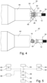
- Fig. 4 shows a system 42 for producing sealed blind rivet joints.
- a blind rivet 34 is shown as in Fig. 2 which is coupled to a tool 44.
- the tool holder head 16 is inserted into a second profile 46 and can thereby be rotated by the tool 44.
- the tool 44 has a tool nose piece 48, which has a nose surface 50 which can be brought into contact with the sealing ring 28 and which is arranged, for example, in a ring shape around a receiving opening 52 of the tool 44.
- This can act on the sealing ring 28 when the rivet body 12 contracts, so that it, as in the lower illustration of Fig. 4 shown forms the sealing material layer 30.
- the nose surface 50 can have engagement elements 51 which engage in the notches 40 of the rivet body 8, if such are provided and desired.
- Fig. 5 a method for producing sealed blind rivet connections of workpieces and comprises the steps of preparing 54 the rivet bore 6 in the workpieces 4a and 4b, inserting 56 the blind rivet 2 or 34 into the rivet bore 6, and contracting 58 the rivet body 8 by the tool 44 while pressing the at least one sealing ring 28.
- the at least one sealing ring 28 can be a two-component mixture which is formed 60 into an annular bead before insertion 56 of the blind rivet 2 or 34 and placed 62 onto the blind rivet 2 or 34.
- the at least one sealing ring 28 could, however, be removed 64 from an airtight and/or cooled packaging directly before insertion 56 of the blind rivet 2 or 34 and placed 62 onto the blind rivet 2 or 34, or the blind rivet 2 or 34 could be removed 66 with the sealing ring 28 attached directly before insertion 56 from an airtight and/or cooled packaging.
- the sealing material can be filled 68.
Landscapes
- Engineering & Computer Science (AREA)
- General Engineering & Computer Science (AREA)
- Mechanical Engineering (AREA)
- Insertion Pins And Rivets (AREA)
- Slide Fasteners, Snap Fasteners, And Hook Fasteners (AREA)
Description
- Die vorliegende Beschreibung betrifft einen Blindniet sowie ein System und ein Verfahren zum Herstellen von abgedichteten Blindnietverbindungen.
- Im Flugzeugbau werden zum Zusammensetzen einzelner Flugzeugbauteile üblicherweise zahlreiche Nietverbindungen eingesetzt. Herkömmliche Nietverbindungen sind hierbei zweiteilig ausgeführt und umfassen einen Niet und eine Nietmutter. Zur Herstellung der Nietverbindungen sind eine Nietbohrung und ein beidseitiger Zugang zu der Nietbohrung erforderlich, um von einer Seite den Niet in die Nietbohrung zu stecken und auf der anderen Seite die Nietmutter auf den Niet aufzufädeln. Dies ist zeitaufwändig, je nach Ausführung der Werkstücke schwierig oder umständlich. Bei größeren Werkstücken, die nicht nur randseitig miteinander vernietet werden sind zudem zwei Personen erforderlich, die den Niet und die Nietmutter anbringen.
- Eine vereinfachte Variante zum Herstellen von Nietverbindungen verwendet Blindniete, die lediglich einen einseitigen Zugang zu einer Nietbohrung erfordern und zudem durch entsprechende Werkzeuge automatisierbar sind (vgl.
US 2014/0044498 A1 ). Neben einer signifikanten Reduktion der Installationszeit, der Kosten und der Geräuschentwicklung werden aufgrund der reduzierten Zugänglichkeitsanforderungen neue, andersartige Gestaltungen möglich. Die Ergonomie wird erhöht und für die Herstellung einer Nietverbindung wird lediglich eine einzelne Person erfordert. - Insbesondere bei der Verbindung von Flugzeugkomponenten, welche in direkten Kontakt mit der Umgebung treten, können bei Blindnietverbindungen jedoch abzudichtende Zwischenräume, Vertiefungen oder Spalte auftreten, um eine darauf aufgebrachte Lackschicht lückenlos und glatt aufbringen zu können. Eine geeignete Nachbehandlung umfasst üblicherweise das Aufbringen eines Dichtmaterials auf die Nietverbindungen, das Verspachteln und das anschließende Entfernen überschüssigen Dichtmaterials. Dies kann jedoch unter Umständen aufwändig sein und zumindest teilweise den Zeitgewinn und die Kostenreduktion bei der Blindnietmontage wieder ausgleichen.
- Es ist folglich eine Aufgabe der Erfindung, einen Blindniet, ein Verbindungssystem und/oder ein Verfahren zum Herstellen einer Blindnietverbindung vorzuschlagen, bei dem der manuelle Aufwand bei der Nachbehandlung reduzierbar ist.
- Diese Aufgabe wird gelöst durch einen Blindniet mit den Merkmalen des unabhängigen Anspruchs 1. Vorteilhafte Ausführungsformen und Weiterbildungen der Erfindung sind den Unteransprüchen und der nachfolgenden Beschreibung zu entnehmen.
- Es wird ein Blindniet zum Verbinden von Werkstücken vorgeschlagen, aufweisend einen hohlen, verformbaren Nietkörper mit einem Auflagekragen und einer sich hieran anschließenden Hülse, einen in der Hülse angeordneten und sich durch den Auflagekragen erstreckenden Nietdorn mit einem Werkzeugaufnahmekopf, und mindestens einen Dichtring, wobei der mindestens eine Dichtring zwischen dem Auflagekragen und dem Werkzeugaufnahmekopf angeordnet ist, wobei der mindestens eine Dichtring aus einem aushärtbaren und nicht vollständig ausgehärteten Dichtmaterial besteht, wobei der mindestens eine Dichtring so angeordnet ist, dass er bei einer Kontraktion des Blindniets von einem mit dem Werkzeugaufnahmekopf verbindbaren Werkzeug oder von einem Abschnitt des Nietdorns axial zu dem Auflagekragen gepresst wird, und wobei der mindestens eine Dichtring dazu ausgebildet ist, beim Pressen des Dichtrings radial und axial in Spalte und Zwischenräume auf dem Auflagekragen und zwischen dem Auflagekragen und den Werkstücken zu fließen und dort anzuhaften.
- Es wird erfindungsgemäß ein alternativer Blindniet vorgeschlagen, der bei einer werkzeuggeführten Kontraktion automatisch zur vollständigen Abdichtung der Blindnietverbindung an den Werkstücken führt. Es können herkömmliche Werkzeuge zum Befestigen des Blindniets eingesetzt werden, die auch bei üblichen Nietprozessen Verwendung finden. Die vorangehend erläuterten Vorteile der Blindnietverbindung gegenüber einer herkömmlichen Nietverbindung können aufrechterhalten werden, gleichzeitig wird jedoch der Aufwand für Nacharbeiten, insbesondere von Schleifarbeiten, deutlich reduziert, indem ein automatisches Füllen von Spalten und Zwischenräumen erfolgt. Die hierfür notwendigen, wesentlichen Komponenten des Blindniets werden weiter nachfolgend beschrieben.
- Der Nietkörper besteht im Wesentlichen aus der Hülse, die in eine Nietbohrung der zu verbindenden Werkstücke gesteckt wird. Die Einstecktiefe wird durch den Auflagekragen begrenzt, der sich auf eine die Nietbohrung umgebende Randfläche legt. Die Hülse ist derart konzipiert, dass sie durch eine Zugkraft, welche ein von der Nietbohrung abgewandtes Ende der Hülse in Richtung der Nietbohrung zieht, verformt. Hierbei wird die Hülse in axialer Richtung verkürzt und weitet sich in radialer Richtung auf, sodass sie an einer von dem Auflagekragen abgewandten Seite an die Werkstücke gequetscht wird. Diese werden dann zwischen dem Auflagekragen und dem verformten Teil der Hülse eingeklemmt.
- Der Nietdorn ist dafür vorgesehen, den Nietkörper wie beschrieben zu der Nietbohrung zu ziehen. Dies kann auf unterschiedliche Weise geschehen. In einer ersten Variante könnte der Nietdorn lediglich eine zugfeste Verbindung mit dem von dem Auflagekragen abgewandten Ende des Nietkörpers aufweisen und durch das an den Nietdorn gesetzte Werkzeug gezogen werden. In einer zweiten Variante könnten die Hülse ein Innengewinde und der Nietdorn ein komplementäres Außengewinde aufweisen. Durch das Werkzeug angetrieben kann der Nietdorn rotiert werden, sodass durch die ineinandergreifenden Gewinde eine Zugkraft auf das betreffende Ende des Nietkörpers ausgeführt wird, welches zur gewünschten Verformung der Hülse führt.
- Der Werkzeugaufnahmekopf ist dazu vorgesehen, eine Verbindung zwischen dem Nietdorn und dem Werkzeug herzustellen. Der Werkzeugaufnahmekopf kann eine drehfeste oder zugfeste Bindung herstellen, je nach Ausführung des Nietdorns.
- Die vorbeschriebenen Komponenten sind bei üblichen Blindnieten gängig. Ein wesentliches Element des erfindungsgemäßen Blindniets ist jedoch der mindestens eine Dichtring, der zwischen dem Auflagekragen und dem Werkzeugaufnahmekopf angeordnet ist. Der Dichtring kann vor der Montage des Blindniets aus einem Behälter entnommen und auf den Blindniet aufgesetzt werden. Alternativ dazu ist der Dichtring vor der Montage bereits auf dem Blindniet angeordnet. Hierbei ist anzumerken, dass die Positionsangabe derart zu verstehen ist, dass der Dichtring in einer allgemeinen Form an einer beliebigen oder gewünschten Stelle zwischen dem Werkzeugaufnahmekopf und dem Auflagekragen angeordnet sein könnte, je nach Ausführung des Nietdorns und nach Wunsch des Benutzers. Verschiedene Varianten der Positionierung werden weiter nachfolgend erläutert.
- Das Material des Dichtrings ist so ausgebildet, dass der Dichtring sehr zähflüssig oder pastös ist, sodass in einem unbelasteten Zustand des Blindniets die Form eines Rings beibehalten wird und ein Benutzer den Dichtring auch einfach auf den Blindniet aufbringen könnte bzw. der mindestens eine Dichtring in einer gelagerten Form des Blindniets seine Ringform behält. Allerdings ist das Dichtmaterial ausreichend plastisch verformbar, sodass beim Aufpressen des Dichtrings seine Form dauerhaft verändert wird. Es ist besonders sinnvoll, die Viskosität derart zu wählen, dass der mindestens eine Dichtring nach der Kontraktion des Blindniets glattstreichbar bleibt. Er sollte folglich auch nicht zu zähflüssig sein.
- Der Dichtring könnte sich bei dem Herstellen der Nietverbindung, insbesondere nach dem Einsetzen des Blindniets in eine Nietbohrung, beispielsweise in einem nicht vollständig ausgehärteten Zustand befinden und nach dem Kontrahieren des Blindniets und dem Herstellen der Dichtung aushärten. Folglich kann auch bei einer automatisierten, werkzeuggeführten Herstellung von Blindnietverbindungen automatisch eine Abdichtung erfolgen. Sowohl der Auftragsort, als auch die Auftragsmenge sind dabei direkt an die Anforderungen der erstellten Nietverbindung angepasst. Das Dichtmaterial ist bevorzugt aushärtbar, um eine homogene, dauerhafte Basis für eine Grundierung oder Lackierung bereitzustellen. Beispielhaft basiert das Dichtmaterial auf Polysulfiden. Ein geeigneter Härter könnte Mangandioxid oder ähnliches umfassen.
- In einer vorteilhaften Ausführungsform umfasst der Nietdorn an einem von dem Werkzeugaufnahmekopf abgewandten Ende ein Außengewinde, das mit einem Innengewinde in der Hülse korrespondiert, wobei der Werkzeugaufnahmekopf zum Übertragen einer Rotation des Werkzeugs in den Nietdorn ein erstes Profil aufweist, das mit einem zweiten Profil eines Werkzeugs korrespondiert. Damit wird der Nietkörper durch Rotation des Nietdorns aufgrund der ineinandergreifenden Gewinde kontrahiert. Nach Erreichen eines Grenzdrehmoments, das auf die mechanischen Eigenschaften des Nietkörpers abgestimmt ist und nach vollständiger Kontraktion erreicht wird, bricht der Werkzeugaufnahmekopf ab. Der Werkzeugaufnahmekopf und das Werkzeug können ein elliptisches Antriebssystem umfassen. Weiterhin kann der Nietkörper an seiner von dem Werkzeugaufnahmekopf abgewandten Seite eine Öffnung aufweisen, durch die der Nietdorn bei der Kontraktion des Nietkörpers herausragen kann.
- In einer vorteilhaften Ausführungsform weist der Nietdorn einen umlaufenden Kragen auf, der auf dem Auflagekragen des Nietkörpers aufliegt. Der umlaufende Kragen, der in dem vorangehend genannten Abschnitt des Nietdorns angeordnet sein kann oder diesen darstellt, presst sich bei der Kontraktion in eine Öffnung des Auflagekragens. Die Öffnung des Auflagekragens und der umlaufende Kragen des Nietdorns könnten jeweils eine Fase aufweisen, die aufeinander abgestimmt sind. Hierdurch könnte der umlaufende Kragen eine gewisse Kegelstumpfform aufweisen, die in eine ebenso kegelstumpfförmige Öffnung eingepresst wird. Der Nietdorn und der Nietkörper werden dadurch zueinander zentriert.
- In einer vorteilhaften Ausführungsform ist der mindestens eine Dichtring zwischen dem umlaufenden Kragen und dem Auflagekragen angeordnet. Ausgehend von dem Nietdorn und der Öffnung des Nietkörpers breitet sich das Dichtmaterial folglich radial nach außen aus und überdeckt bevorzugt den Auflagekragen des Nietkörpers weitgehend vollständig.
- In einer vorteilhaften Ausführungsform ist der mindestens eine Dichtring zwischen dem Werkzeugaufnahmekopf und dem umlaufenden Kragen angeordnet. Dann wirkt ein Werkzeugnasenstück bei der Kontraktion des Nietkörpers auf den mindestens einen Dichtring ein, sodass dieser ausgehend von dem umlaufenden Kragen radial nach außen über den Auflagekragen des Nietkörpers gequetscht wird. Bei dieser Variante ist zu beachten, dass das Werkzeugnasenstück frei von Verschmutzungen ist und gegebenenfalls regelmäßig mit einem Trennmittel benetzt wird. Das Trennmittel ist bevorzugt auf das Dichtmaterial abgestimmt und dazu ausgebildet, eine Anhaftung des Dichtmaterials zu vermeiden.
- In einer vorteilhaften Ausführungsform weist der Auflagekragen an einer von dem Werkzeugaufnahmekopf abgewandten Seite Vorsprünge auf, die sich bei der Kontraktion des Blindniets mit den Werkstücken zum Verhindern einer Rotation des Nietkörpers verklemmen. Die Vorsprünge werden durch das Werkzeug und/oder den umlaufenden Kragen, der auf den Auflagekragen drückt, auf eine dem Auflagekragen zugewandte Oberfläche der Werkstücke gepresst. Hierdurch wird die Lage des Nietkörpers an den Werkstücken insbesondere drehfest fixiert.
- Durch den mindestens einen Dichtring kann das Dichtmaterial automatisch in etwaige Spalte oder Zwischenräume eingebracht werden.
- In einer vorteilhaften Ausführungsform weist der Aufnahmekragen Einkerbungen auf einer zu dem Werkzeugaufnahmekopf gerichteten Seite auf, wobei der Dichtring derart dimensioniert ist, dass die Einkerbungen nach der Kontraktion des Blindniets mit dem Dichtmaterial gefüllt sind. Das Dichtmaterial wird radial auch über die Einkerbungen gedrängt, sodass diese nach der Kontraktion des Nietkörpers automatisch mit dem Dichtmaterial benetzt sind. Es kann gewünscht sein, anschließend eine ebene Oberfläche durch Spachteln herzustellen. Dies kann entweder für jede Nietverbindung direkt im Anschluss an die Kontraktion oder für eine gesamte Nietreihe oder ähnliche Anordnung durchgeführt werden. Die Einkerbungen könnten dafür vorgesehen sein, mit einer nicht rotierenden Nasenfläche des Werkzeugs in Eingriff zu geraten, um einer Rotation entgegenzuwirken. Da die Einkerbungen teilweise mit der Nasenfläche in Kontakt stehen, könnte es erforderlich sein, nach Entnahme des Werkzeugs das Dichtmaterial mit einem Spachtel glattzuziehen, um die Einkerbungen dann vollständig zu füllen.
- In einer vorteilhaften Ausführungsform ist der Werkzeugaufnahmekopf frei von Cetyl-Alkohol. Cetyl-Alkohol wird oftmals als Schmiermittel für Verbindungsmittel verwendet und üblicherweise auf die gesamten Verbindungsmittel gebracht. Um ein einwandfreies Abdichten der hergestellten Nietverbindung zu erreichen, ist es sinnvoll, an dem Werkzeugaufnahmekopf, dem umlaufenden Kragen und/oder dem Auflagekragen Cetyl-Alkohol zu vermeiden. Der Blindniet kann demnach nur an einem von dem Auflagekragen abgewandten Abschnitt entsprechend benetzt werden oder die Benetzung mit einem solchen Schmiermittel wird im Bereich des Auflagekragens entfernt.
- In einer vorteilhaften Ausführungsform weist der Blindniet eine Harzbeschichtung auf. Beispielhaft könnten aluminiumpigmentierte Beschichtungen gemäß EN 4473 eingesetzt werden. Eine Harzbeschichtung ist besonders vorteilhaft für die Adhäsion des Dichtmaterials bzw. einer Grundierung oder Lackschicht.
- In einer vorteilhaften Ausführungsform ist der mindestens eine Dichtring wärmehärtbar, UV-härtbar und/oder feuchtigkeitshärtend. Ein Aushärten des Dichtmaterials kann durch entsprechende Anwendung von Wärme oder UV-Licht gesteuert werden. Es ist indes denkbar, durch Luftfeuchtigkeit in der Umgebung ein Aushärten zu initiieren. Nach dem Anbringen des mindestens eine Dichtrings müssen in letzterem Fall folglich keine weiteren Vorkehrungen getroffen werden. Der Blindniet könnte weiterhin in einem gekühlten Zustand gelagert werden, sodass eine Aushärtung des Dichtrings aus einem wärmehärtbaren Dichtmaterial unterbrochen wird, wobei nach Anfertigen der Blindnietverbindung durch die Umgebungstemperatur die Aushärtung erfolgt.
- In einer vorteilhaften Ausführungsform ist der mindestens eine Dichtring direkt nach der Kontraktion des Blindniets spachtelbar. Das Dichtmaterial darf in dem aufgebrachten Zustand folglich nicht zu zähflüssig sein, sodass es manuell mit einem Spachtel entsprechend verteilt bzw. geglättet werden kann. Es muss jedoch ausreichend pastös bzw. zähflüssig sein, um seine Form nach dem Spachteln auch beizubehalten und nicht abzufließen oder abzutropfen, falls die Verbindung nicht vollständig horizontal angeordnet ist.
- In einer vorteilhaften Ausführungsform ist der mindestens eine Dichtring ein Zwei-Komponenten-Gemisch, das vor dem Anbringen des mindestens einen Dichtrings hergestellt oder in Form zweier in Kontakt bringbarer Dichtringe mit voneinander getrennten und bei Kontraktion sich miteinander vermischenden Komponenten realisiert ist. Die beiden Dichtringe bilden folglich das aushärtbare Dichtmaterial erst nach einer entsprechenden Verpressung der beiden Dichtringe miteinander.
- Die Erfindung betrifft ferner ein System zum Herstellen von abgedichteten Blindnietverbindungen, aufweisend mindestens einen Blindniet gemäß der vorhergehenden Beschreibung und mindestens ein mit dem Werkzeugaufnahmekopf verbindbares Werkzeug. Das Werkzeug ist auf die Ausführung des Blindniets angepasst und könnte sowohl zur Ausübung einer reinen Zugkraft vorgesehen sein, als auch zur Ausübung einer Rotation. Das Werkzeug könnte elektrisch oder pneumatisch ausgeführt sein.
- In einer vorteilhaften Ausführungsform weist das Werkzeug ein Werkzeugnasenstück auf, das eine mit dem mindestens einen Dichtring in Berührung bringbare Nasenfläche aufweist, wobei die Nasenfläche mit einem Trennmittel benetzt ist. Das Werkzeugnasenstück kann eine Nietdornaufnahme aufweisen, das von einer beispielhaft ringförmigen Fläche umgeben ist. Diese kann bei der Kontraktion des Blindniets auf den Nietkörper drücken. Befindet sich der mindestens eine Dichtring zwischen dem Auflagekragen und dem Werkzeugaufnahmekopf, kann die Nasenfläche auf den mindestens einen Dichtring drücken und folglich das Dichtmaterial wie vorangehend beschrieben axial und radial verpressen. Durch das Trennmittel kann ein Anhaften vermieden werden. Es ist bevorzugt, die Sauberkeit des Werkzeugnasenstücks regelmäßig zu prüfen und es beispielsweise regelmäßig mit einem fusselfreien Tuch abzuwischen und gegebenenfalls mit einem Trennmittel zu benetzen.
- Weiterhin betrifft die Erfindung ein Verfahren zum Herstellen von abgedichteten Blindnietverbindungen von Werkstücken, aufweisend die Schritte des Anfertigens einer Nietbohrung in den Werkstücken, des Einsteckens eines erfindungsgemäßen Blindniets in die Nietbohrung und des Kontrahierens des Nietkörpers durch ein Werkzeug unter Verpressung des mindestens einen Dichtrings. Anschließend könnte ein Verspachteln des Dichtmaterials erfolgen, falls gewünscht.
- In einer vorteilhaften Ausführungsform ist der mindestens eine Dichtring ein Zwei-Komponenten-Gemisch, das vor dem Einsetzen des Blindniets zu einer ringförmigen Raupe geformt und auf den Blindniet aufgesetzt wird.
- In einer vorteilhaften Ausführungsform wird der mindestens eine Dichtring direkt vor dem Einsetzen des Blindniets aus einer luftdichten und/oder gekühlten Verpackung entnommen und auf den Blindniet aufgesetzt oder der Blindniet mit aufgesetztem Dichtring wird direkt vor dem Einsetzen aus einer luftdichten und/oder gekühlten Verpackung entnommen.
- Weiterhin kann das Verfahren das Spachteln des Dichtmaterials nach dem Verpressen des mindestens einen Dichtrings umfassen.
- Nachfolgend wird anhand der beigefügten Zeichnungen näher auf Ausführungsbeispiele eingegangen. Die Darstellungen sind schematisch und nicht maßstabsgetreu. Gleiche Bezugszeichen beziehen sich auf gleiche oder ähnliche Elemente. Es zeigen:
- Fig. 1
- eine schematische Darstellung eines Blindniets gemäß einem Ausführungsbeispiel in einem unkontrahierten, neutralen Zustand und einem kontrahierten Zustand.
- Fig. 2
- eine schematische Darstellung eines Blindniets gemäß einem weiteren Ausführungsbeispiel.
- Fig. 3
- eine schematische Darstellung eines Auflagekragens.
- Fig. 4
- eine schematische Darstellung eines Systems zum Herstellen von Blindnietverbindungen.
- Fig. 5
- eine schematische Darstellung eines Verfahrens zum Herstellen von Blindnietverbindungen.
-
Fig. 1 zeigt einen Blindniet 2 zum Verbinden von Werkstücken 4a und 4b. Diese könnten beispielsweise aus einem metallischen Blech oder einem Kunststoffmaterial, gegebenenfalls mit Faserverstärkung, bestehen und für ein Flugzeugbauteil oder ähnliches Verwendung finden. Die beiden Werkstücke 4a und 4b liegen bündig aufeinander und weisen eine Nietbohrung 6 auf, die sich vollständig durch beide Werkstücke 4a und 4b erstreckt. Der Blindniet 2 ist in die Nietbohrung 6 eingesteckt und befindet sich auf der linken Seite der Zeichnungsebene in einem neutralen (Liefer-)Zustand. - Der Blindniet 2 umfasst einen hohlen, verformbaren Nietkörper 8 mit einem Auflagekragen 10 und einer sich hieran anschließenden Hülse 12. In der Hülse 12 befindet sich ein Nietdorn 14, der einen außerhalb der Hülse 12 positionierten Werkzeugaufnahmekopf 16 umfasst. Die Hülse 12 weist an einem vom Werkzeugaufnahmekopf 16 abgewandten Ende 18 ein Innengewinde 20 auf, während der Nietdorn 14 an dieser Stelle ein hierzu komplementäres Außengewinde 22 umfasst. Durch Rotation des Nietdorns 14 wird, bei gleichbleibender Lage des Nietdorns 14, das Ende 18 der Hülse 12 an dem Außengewinde 22 in Richtung der Nietbohrung 6 gedrängt. Die Hülse 12 verformt sich dann entsprechend. Dies ist in der Zeichnungsebene auf der rechten Seite gezeigt. Durch die Verformung entstehen radiale Auswölbungen 24 der Hülse 12, die die Werkstücke 4a und 4b zusammen mit dem Auflagekragen 10 zusammenquetschen.
- Beispielhaft weist der Nietdorn 14 einen umlaufenden Kragen 26 auf, der während der Kontraktion der Hülse 12 in Richtung des Auflagekragens 10 gepresst wird. Zwischen dem umlaufenden Kragen 26 und dem Auflagekragen 10 befindet sich ein Dichtring 28, der aus einem aushärtbaren Dichtmaterial besteht. Das Dichtmaterial befindet sich nach Positionierung an dem Blindniet 2 in einem Zustand, der eine ringförmige Anordnung um den Nietdorn 14 ermöglicht, dennoch ausreichend pastös bzw. plastisch verformbar ist, sodass das Material während der Kontraktion des Nietkörpers 8 radial verpresst werden kann. Bei der Kontraktion des Nietkörpers 8 und dem Aufdrücken des umlaufenden Kragen 26 auf den Auflagekragen 10 wird folglich durch Verpressen des Dichtrings 28 eine Dichtmaterialschicht 30 hergestellt, die sich bei entsprechender Dimensionierung des Dichtrings 28 vollständig über den Auflagekragen 10 erstreckt. Etwaige Spalte oder Zwischenräume zwischen dem äußeren Werkstück 4a und dem Auflagekragen 10 bzw. zwischen dem Auflagekragen 10 und dem umlaufenden Kragen 26 werden dadurch vollständig abgedeckt. Es könnte sinnvoll sein, anschließend das Dichtmaterial zu spachteln bzw. mit einem Spachtel glatt zu ziehen.
- Auf der rechten Seite der
Fig. 1 ist der Werkzeugaufnahmekopf 16 in einem abgebrochenen Zustand dargestellt, der durch vollständige Kontraktion des Nietkörpers 8 durch Überschreiten eines vorbestimmten Grenzdrehmoments erreicht wird. Die Nietverbindung ist dann vollständig. Beispielhaft weist der Werkzeugaufnahmekopf 16 ein erstes Profil 32 auf, das mit einem zweiten Profil eines Werkzeugs (hier nicht gezeigt) zur Verbindung von Werkzeug und Werkzeugaufnahmekopf 16 komplementär ausgebildet ist. -
Fig. 2 zeigt eine alternative Gestaltung eines Blindniets 34, bei dem der Nietkörper 8 auf dieselbe Weise ausgestaltet ist, der Nietdorn 14 jedoch keinen umlaufenden Kragen 26 umfasst. Der Dichtring 28 ist direkt zwischen dem Werkzeugaufnahmekopf 16 und dem Auflagekragen 10 angeordnet. Beim Kontrahieren des Nietkörpers 8 wird ein Werkzeugnasenstück (sieheFig. 4 ) über den Dichtring 28 auf den Auflagekragen 10 aufgepresst, sodass hierdurch ein Verpressen des Dichtmaterials erfolgt. - In
Fig. 3 wird der Auflagekragen 10 in einer schrägen Draufsicht gezeigt. Auf einer von den Werkzeugaufnahmekopf 16 abgewandten Unterseite 36 weist der Auflagekragen 10 beispielhaft mehrere, über dem Auflagekragen 10 verteilte Vorsprünge 38 auf. Die Vorsprünge 38 pressen sich in das äußere Werkstück 4a ein, sodass hierdurch einer Rotation des Nietkörpers 8 entgegengewirkt wird. - Es ist denkbar, auch auf der zu dem Werkzeugaufnahmekopf 16 gewandten Seite Einkerbungen 40 vorzusehen, die mit dem Werkzeugnasenstück (siehe
Fig. 4 ) formschlüssig in Eingriff bringbar sind, um einer Rotation des Nietkörpers 8 entgegenzuwirken. Durch Verpressen des Dichtmaterials werden die Einkerbungen 40 mit dem Dichtmaterial gefüllt. Ein anschließendes Verspachteln kann das Dichtmaterial vollständig in den Einkerbungen 40 verteilen. -
Fig. 4 zeigt ein System 42 zum Herstellen von abgedichteten Blindnietverbindungen. Hier ist ein Blindniet 34 wie inFig. 2 dargestellt, das mit einem Werkzeug 44 gekoppelt ist. Der Werkzeugaufnahmekopf 16 steckt dabei in einem zweiten Profil 46 und kann hierdurch von dem Werkzeug 44 rotiert werden. Das Werkzeug 44 weist ein Werkzeugnasenstück 48 auf, welches eine mit dem Dichtring 28 in Berührung bringbare Nasenfläche 50 aufweist, die beispielhaft ringförmig um eine Aufnahmeöffnung 52 des Werkzeugs 44 angeordnet ist. Diese kann beim Kontrahieren des Nietkörpers 12 auf den Dichtring 28 einwirken, sodass dieser wie in der unteren Darstellung vonFig. 4 dargestellt die Dichtmaterialschicht 30 bildet. Lediglich beispielhaft kann die Nasenfläche 50 Eingriffselemente 51 aufweisen, die in die Einkerbungen 40 des Nietkörpers 8 eingreifen, falls solche vorgesehen und gewünscht sind. - Schließlich zeigt
Fig. 5 ein Verfahren zum Herstellen von abgedichteten Blindnietverbindungen von Werkstücken und weist die Schritte des Anfertigens 54 der Nietbohrung 6 in den Werkstücken 4a und 4b, des Einsteckens 56 des Blindniets 2 bzw. 34 in die Nietbohrung 6, und des Kontrahierens 58 des Nietkörpers 8 durch das Werkzeug 44 unter Verpressung des mindestens einen Dichtrings 28. Dabei kann der mindestens eine Dichtring 28 ein Zwei-Komponenten-Gemisch sein, das vor dem Einsetzen 56 des Blindniets 2 bzw. 34 zu einer ringförmigen Raupe geformt 60 und auf den Blindniet 2 bzw. 34 aufgesetzt werden 62. Der mindestens eine Dichtring 28 könnte indes direkt vor dem Einsetzen 56 des Blindniets 2 bzw. 34 aus einer luftdichten und/oder gekühlten Verpackung entnommen 64 und auf den Blindniet 2 bzw. 34 aufgesetzt 62 werden oder der Blindniet 2 bzw. 34 könnte mit aufgesetztem Dichtring 28 direkt vor dem Einsetzen 56 aus einer luftdichten und/oder gekühlten Verpackung entnommen werden 66. - Nach der Fertigstellung der Blindnietverbindung kann das Dichtmaterial gespachtelt werden 68.
-
- 2
- Blindniet
- 4a, 4b
- Werkstück
- 6
- Nietbohrung
- 8
- Nietkörper
- 10
- Auflagekragen
- 12
- Hülse
- 14
- Nietdorn
- 16
- Werkzeugaufnahmekopf
- 18
- Ende
- 20
- Innengewinde
- 22
- Außengewinde
- 24
- radiale Auswölbung
- 26
- umlaufender Kragen
- 28
- Dichtring
- 30
- Dichtmaterialschicht
- 32
- erstes Profil
- 34
- Blindniet
- 36
- Unterseite
- 38
- Vorsprung
- 40
- Einkerbung
- 42
- System
- 44
- Werkzeug
- 46
- zweites Profil
- 48
- Werkzeugnasenstück
- 50
- Nasenfläche
- 52
- Aufnahmeöffnung
- 54
- Anfertigen Nietbohrung
- 56
- Einstecken des Blindniets
- 58
- Kontrahieren des Nietkörpers
- 60
- Formen zu ringförmiger Raupe
- 62
- Aufsetzen auf Blindniet
- 64
- Entnehmen Dichtring aus luftdichter und/oder gekühlter Verpackung
- 66
- Entnehmen Blindniet aus luftdichter und/oder gekühlter Verpackung
- 68
- Spachteln
Claims (17)
- Blindniet (2, 34) zum Verbinden von Werkstücken (4a, 4b), aufweisendeinen hohlen, verformbaren Nietkörper (8) mit einem Auflagekragen (10) und einer sich hieran anschließenden Hülse (12),einen in der Hülse (12) angeordneten und sich durch den Auflagekragen (10) erstreckenden Nietdorn (14) mit einem Werkzeugaufnahmekopf (16), undmindestens einen Dichtring (28),wobei der mindestens eine Dichtring (28) zwischen dem Auflagekragen (10) und dem Werkzeugaufnahmekopf (16) angeordnet ist,wobei der mindestens eine Dichtring (28) aus einem aushärtbaren und nicht vollständig ausgehärteten Dichtmaterial besteht,wobei der mindestens eine Dichtring (28) so angeordnet ist, dass er bei einer Kontraktion des Blindniets (2, 34) von einem mit dem Werkzeugaufnahmekopf (16) verbindbaren Werkzeug (44) oder von einem Abschnitt des Nietdorns (16) axial zu dem Auflagekragen (10) gepresst wird, undwobei der mindestens eine Dichtring (28) dazu ausgebildet ist, beim Pressen des Dichtrings (28) radial und axial in Spalten und Zwischenräume auf dem Auflagekragen (10) und zwischen dem Auflagekragen (10) und den Werkstücken (4a, 4b) zu fließen und dort anzuhaften.
- Blindniet (2, 34) nach Anspruch 1,wobei der Nietdorn (14) an einem von dem Werkzeugaufnahmekopf (16) abgewandten Ende (18) ein Außengewinde (22) umfasst, das mit einem Innengewinde (20) in der Hülse (12) korrespondiert, undwobei der Werkzeugaufnahmekopf (16) zum Übertragen einer Rotation des Werkzeugs (44) in den Nietdorn (14) ein erstes Profil (32) aufweist, das mit einem zweiten Profil (46) eines Werkzeugs (44) korrespondiert.
- Blindniet (2, 34) nach Anspruch 1,
wobei der Nietdorn (14) einen umlaufenden Kragen (26) aufweist, der auf dem Auflagekragen (10) des Nietkörpers (8) aufliegt. - Blindniet (2, 34) nach Anspruch 3,
wobei der mindestens eine Dichtring (28) zwischen dem umlaufenden Kragen (26) und dem Auflagekragen (10) angeordnet ist. - Blindniet (2, 34) nach Anspruch 3,
wobei der mindestens eine Dichtring (28) zwischen dem Werkzeugaufnahmekopf (16) und dem umlaufenden Kragen (26) angeordnet ist. - Blindniet (2, 34) nach einem der vorhergehenden Ansprüche,
wobei der Auflagekragen (10) an einer von dem Werkzeugaufnahmekopf (16) abgewandten Seite (36) Vorsprünge (38) aufweist, die sich bei der Kontraktion des Blindniets (2, 34) mit den Werkstücken (4a, 4b) zum Verhindern einer Rotation des Nietkörpers (8) verklemmen. - Blindniet (2, 34) nach einem der vorhergehenden Ansprüche,wobei der Auflagekragen (10) Einkerbungen (40) auf einer zu dem Werkzeugaufnahmekopf (16) gerichteten Seite des Auflagekragens (10) aufweist, undwobei der Dichtring (28) derart dimensioniert ist, dass die Einkerbungen (40) nach der Kontraktion des Blindniets (2, 34) mit dem Dichtmaterial gefüllt sind.
- Blindniet (2, 34) nach einem der vorhergehenden Ansprüche,
wobei der Werkzeugaufnahmekopf (16) frei von Cetyl-Alkohol ist. - Blindniet (2, 34) nach einem der vorhergehenden Ansprüche,
wobei der Blindniet (2, 34) eine Harzbeschichtung aufweist. - Blindniet (2, 34) nach einem der vorhergehenden Ansprüche,
wobei der mindestens eine Dichtring (28) wärmehärtbar, UV-härtbar und/oder feuchtigkeitshärtend ist. - Blindniet (2, 34) nach einem der vorhergehenden Ansprüche,
wobei der Dichtring (28) direkt nach der Kontraktion des Blindniets (2, 34) spachtelbar ist. - Blindniet (2, 34) nach einem der vorhergehenden Ansprüche,
wobei der mindestens eine Dichtring (28) ein Zwei-Komponenten-Gemisch ist, das vor dem Anbringen des mindestens einen Dichtrings (28) hergestellt oder in Form zweier in Kontakt bringbarer Dichtringe (28) mit voneinander getrennten und bei Kontraktion sich miteinander vermischenden Komponenten realisiert ist. - System (42) zum Herstellen von abgedichteten Blindnietverbindungen, aufweisend mindestens einen Blindniet (2, 34) nach einem der vorhergehenden Ansprüche und mindestens ein mit dem Werkzeugaufnahmekopf (16) verbindbares Werkzeug (44).
- System (42) nach Anspruch 13,wobei das Werkzeug (44) ein Werkzeugnasenstück (48) aufweist, das eine mit dem mindestens einen Dichtring (28) in Berührung bringbare Nasenfläche (50) aufweist, undwobei die Nasenfläche (50) mit einem Trennmittel benetzt ist.
- Verfahren zum Herstellen von abgedichteten Blindnietverbindungen von Werkstücken (4a, 4b), aufweisend die Schritte:- Anfertigen (54) einer Nietbohrung (6) in den Werkstücken (4a, 4b),- Einstecken (56) eines Blindniets (2, 34) nach einem der vorhergehenden Ansprüche in die Nietbohrung (6), und- Kontrahieren (58) des Nietkörpers (8) durch ein Werkzeug (44) unter Verpressung des mindestens einen Dichtrings (28).
- Verfahren nach Anspruch 15,
wobei der mindestens eine Dichtring (28) ein Zwei-Komponenten-Gemisch ist, das vor dem Einsetzen des Blindniets (2, 34) zu einer ringförmigen Raupe geformt (60) und auf den Blindniet aufgesetzt (62) wird. - Verfahren nach Anspruch 15 oder 16,
wobei der mindestens eine Dichtring (28) direkt vor dem Einsetzen (56) des Blindniets (2, 34) aus einer luftdichten und/oder gekühlten Verpackung entnommen (64) und auf den Blindniet (2, 34) aufgesetzt (62) wird oder wobei der Blindniet (2, 34) mit aufgesetztem Dichtring (28) direkt vor dem Einsetzen (56) aus einer luftdichten und/oder gekühlten Verpackung entnommen (66) wird.
Priority Applications (4)
| Application Number | Priority Date | Filing Date | Title |
|---|---|---|---|
| EP22196041.2A EP4339467B1 (de) | 2022-09-16 | 2022-09-16 | Blindniet, sowie system und verfahren zum herstellen von abgedichteten blindnietverbindungen |
| ES22196041T ES3042424T3 (en) | 2022-09-16 | 2022-09-16 | Blind rivet, and system and method for producing sealed blind rivet connections |
| US18/460,896 US20240093711A1 (en) | 2022-09-16 | 2023-09-05 | Blind rivet, and system and method for making sealed blind rivet joints |
| CN202311150952.7A CN117722425A (zh) | 2022-09-16 | 2023-09-07 | 抽芯铆钉,以及用于建立密封的抽芯铆钉连接的系统和方法 |
Applications Claiming Priority (1)
| Application Number | Priority Date | Filing Date | Title |
|---|---|---|---|
| EP22196041.2A EP4339467B1 (de) | 2022-09-16 | 2022-09-16 | Blindniet, sowie system und verfahren zum herstellen von abgedichteten blindnietverbindungen |
Publications (2)
| Publication Number | Publication Date |
|---|---|
| EP4339467A1 EP4339467A1 (de) | 2024-03-20 |
| EP4339467B1 true EP4339467B1 (de) | 2025-06-25 |
Family
ID=83361135
Family Applications (1)
| Application Number | Title | Priority Date | Filing Date |
|---|---|---|---|
| EP22196041.2A Active EP4339467B1 (de) | 2022-09-16 | 2022-09-16 | Blindniet, sowie system und verfahren zum herstellen von abgedichteten blindnietverbindungen |
Country Status (4)
| Country | Link |
|---|---|
| US (1) | US20240093711A1 (de) |
| EP (1) | EP4339467B1 (de) |
| CN (1) | CN117722425A (de) |
| ES (1) | ES3042424T3 (de) |
Family Cites Families (12)
| Publication number | Priority date | Publication date | Assignee | Title |
|---|---|---|---|---|
| US4102030A (en) * | 1970-04-30 | 1978-07-25 | King John O Jun | Method of forming a sealing sleeve joint construction |
| US3726178A (en) * | 1971-06-25 | 1973-04-10 | Apm Corp | Multiple purpose sealing washer for threaded and cylindrical shanks |
| US3772957A (en) * | 1972-05-22 | 1973-11-20 | Usm Corp | Self-drilling and sealing rivet |
| US5044852B1 (en) * | 1978-08-24 | 1995-04-04 | Sweeney Theodore Co | Vacuum fixed adhesively secured fastener |
| US6012888A (en) * | 1997-08-08 | 2000-01-11 | Theodore Sweeney & Co. | Adhesive fastener and method |
| US6905295B2 (en) * | 2003-07-22 | 2005-06-14 | General Motors Corporation | Blind rivet with extended adhesive reservoir |
| DE102011000603A1 (de) * | 2011-02-09 | 2012-08-09 | Böllhoff Verbindungstechnik GmbH | Verbindungselement zum Aufkleben auf einer Bauteiloberfläche sowie Herstellungsverfahren und Befestigungsverfahren dafür |
| US9249819B2 (en) * | 2012-01-05 | 2016-02-02 | ATS Cases, Inc. | Rivet sealing washer |
| US8979453B2 (en) * | 2012-04-17 | 2015-03-17 | Alcoa Inc. | Blind fastener |
| WO2013158457A1 (en) * | 2012-04-17 | 2013-10-24 | Alcoa Inc. | Blind fastener |
| US11506238B2 (en) * | 2013-06-14 | 2022-11-22 | James Alan Monroe | Thermally stabilized fastener system and method |
| WO2018111610A1 (en) * | 2016-12-13 | 2018-06-21 | Arconic Inc. | Blind bolt fastener with embossments |
-
2022
- 2022-09-16 EP EP22196041.2A patent/EP4339467B1/de active Active
- 2022-09-16 ES ES22196041T patent/ES3042424T3/es active Active
-
2023
- 2023-09-05 US US18/460,896 patent/US20240093711A1/en active Pending
- 2023-09-07 CN CN202311150952.7A patent/CN117722425A/zh active Pending
Also Published As
| Publication number | Publication date |
|---|---|
| ES3042424T3 (en) | 2025-11-20 |
| EP4339467A1 (de) | 2024-03-20 |
| CN117722425A (zh) | 2024-03-19 |
| US20240093711A1 (en) | 2024-03-21 |
Similar Documents
| Publication | Publication Date | Title |
|---|---|---|
| DE102008060930A1 (de) | Kombinierte Falz- und Klebverbindung | |
| EP2570685A1 (de) | Nietelement | |
| WO2015124425A1 (de) | Verfahren zum herstellen einer schraub-klebverbindung unter verwendung einer fliesslochformenden schraube, sowie hierfür verwendbare fliesslochformende schraube | |
| DE102011001522B4 (de) | Verbindungselement zur Herstellung einer Verbindung zwischen wenigstens zwei sich überlappenden Bauteilen und Verfahren zur Herstellung dieser Verbindung | |
| DE102013113763A1 (de) | Klebebolzen und Anbringungsverfahren | |
| DE102004016712B4 (de) | Mit Klebstoff verkapseltes Blindnietsystem | |
| DE69630017T2 (de) | Montagekappeanordnung für aerosolbehälter | |
| EP4339467B1 (de) | Blindniet, sowie system und verfahren zum herstellen von abgedichteten blindnietverbindungen | |
| DE102019103053B4 (de) | Verfahren zur Herstellung der Luftleitvorrichtung | |
| DE102007062087B4 (de) | Hybridfügeverfahren für Überlappverbindungen | |
| DE3328913A1 (de) | Einrichtung zur befestigung eines rohres in einer bohrung | |
| DE102014012562B3 (de) | Verfahren zum Herstellen einer Fügestelle an einem Bauteil aus einem Faserverbundwerkstoff | |
| WO2016202876A1 (de) | Thermoplastischer reibverbinder | |
| WO2012031671A1 (de) | Verfahren zum einbringen einer hülse, insbesondere einer gewindehülse in ein werkstück | |
| DE19712180C2 (de) | Verbindungselement für Kunststoffbauteile | |
| DE102010046318A1 (de) | Fügeelement zum Fügen von wenigstens zwei aneinander liegenden Fügeteilen | |
| DE102016012350B4 (de) | Verfahren zur Herstellung einer Welle-Nabe-Verbindung zwischen einem FKV-Rohrprofilbauteil und einem mit Nabe ausgebildeten Metallbauteil und verfahrensgemäß hergestellter Stabilisator | |
| DE202005015713U1 (de) | Selbststanzender Befestiger und Vorrichtung zum Verbinden des selbststanzenden Befestigers mit einem Kunststoffteil | |
| EP0166134B1 (de) | Blindnietartiges Verbindungselement | |
| DE102014101740B4 (de) | Verfahren zum Verbinden von Bauteilen und Verbindungselement | |
| WO2017080844A1 (de) | Verfahren zum herstellen einer stoffschlüssigen fügeverbindung und verbindungsanordnung | |
| EP3123037A1 (de) | Hülseneinsatz | |
| EP3719329B1 (de) | Heftvorrichtung zum zumindest temporären befestigen von bauteilen aneinander | |
| DE102024133328B3 (de) | Verfahren zur Herstellung eines Brandschutzelements | |
| DE102013224154A1 (de) | Blindniet mit innerer und äußerer Niethülse, sowie Verfahren zum Blindnieten |
Legal Events
| Date | Code | Title | Description |
|---|---|---|---|
| PUAI | Public reference made under article 153(3) epc to a published international application that has entered the european phase |
Free format text: ORIGINAL CODE: 0009012 |
|
| STAA | Information on the status of an ep patent application or granted ep patent |
Free format text: STATUS: THE APPLICATION HAS BEEN PUBLISHED |
|
| AK | Designated contracting states |
Kind code of ref document: A1 Designated state(s): AL AT BE BG CH CY CZ DE DK EE ES FI FR GB GR HR HU IE IS IT LI LT LU LV MC MK MT NL NO PL PT RO RS SE SI SK SM TR |
|
| STAA | Information on the status of an ep patent application or granted ep patent |
Free format text: STATUS: REQUEST FOR EXAMINATION WAS MADE |
|
| 17P | Request for examination filed |
Effective date: 20240920 |
|
| RBV | Designated contracting states (corrected) |
Designated state(s): AL AT BE BG CH CY CZ DE DK EE ES FI FR GB GR HR HU IE IS IT LI LT LU LV MC MK MT NL NO PL PT RO RS SE SI SK SM TR |
|
| GRAP | Despatch of communication of intention to grant a patent |
Free format text: ORIGINAL CODE: EPIDOSNIGR1 |
|
| STAA | Information on the status of an ep patent application or granted ep patent |
Free format text: STATUS: GRANT OF PATENT IS INTENDED |
|
| INTG | Intention to grant announced |
Effective date: 20250213 |
|
| GRAS | Grant fee paid |
Free format text: ORIGINAL CODE: EPIDOSNIGR3 |
|
| GRAA | (expected) grant |
Free format text: ORIGINAL CODE: 0009210 |
|
| STAA | Information on the status of an ep patent application or granted ep patent |
Free format text: STATUS: THE PATENT HAS BEEN GRANTED |
|
| AK | Designated contracting states |
Kind code of ref document: B1 Designated state(s): AL AT BE BG CH CY CZ DE DK EE ES FI FR GB GR HR HU IE IS IT LI LT LU LV MC MK MT NL NO PL PT RO RS SE SI SK SM TR |
|
| REG | Reference to a national code |
Ref country code: GB Ref legal event code: FG4D Free format text: NOT ENGLISH |
|
| REG | Reference to a national code |
Ref country code: CH Ref legal event code: EP |
|
| REG | Reference to a national code |
Ref country code: CH Ref legal event code: EP |
|
| REG | Reference to a national code |
Ref country code: IE Ref legal event code: FG4D Free format text: LANGUAGE OF EP DOCUMENT: GERMAN |
|
| REG | Reference to a national code |
Ref country code: DE Ref legal event code: R096 Ref document number: 502022004390 Country of ref document: DE |
|
| PG25 | Lapsed in a contracting state [announced via postgrant information from national office to epo] |
Ref country code: FI Free format text: LAPSE BECAUSE OF FAILURE TO SUBMIT A TRANSLATION OF THE DESCRIPTION OR TO PAY THE FEE WITHIN THE PRESCRIBED TIME-LIMIT Effective date: 20250625 |
|
| PGFP | Annual fee paid to national office [announced via postgrant information from national office to epo] |
Ref country code: DE Payment date: 20250919 Year of fee payment: 4 |
|
| REG | Reference to a national code |
Ref country code: LT Ref legal event code: MG9D |
|
| PG25 | Lapsed in a contracting state [announced via postgrant information from national office to epo] |
Ref country code: GR Free format text: LAPSE BECAUSE OF FAILURE TO SUBMIT A TRANSLATION OF THE DESCRIPTION OR TO PAY THE FEE WITHIN THE PRESCRIBED TIME-LIMIT Effective date: 20250926 Ref country code: NO Free format text: LAPSE BECAUSE OF FAILURE TO SUBMIT A TRANSLATION OF THE DESCRIPTION OR TO PAY THE FEE WITHIN THE PRESCRIBED TIME-LIMIT Effective date: 20250925 |
|
| PG25 | Lapsed in a contracting state [announced via postgrant information from national office to epo] |
Ref country code: BG Free format text: LAPSE BECAUSE OF FAILURE TO SUBMIT A TRANSLATION OF THE DESCRIPTION OR TO PAY THE FEE WITHIN THE PRESCRIBED TIME-LIMIT Effective date: 20250625 |
|
| PG25 | Lapsed in a contracting state [announced via postgrant information from national office to epo] |
Ref country code: HR Free format text: LAPSE BECAUSE OF FAILURE TO SUBMIT A TRANSLATION OF THE DESCRIPTION OR TO PAY THE FEE WITHIN THE PRESCRIBED TIME-LIMIT Effective date: 20250625 |
|
| PGFP | Annual fee paid to national office [announced via postgrant information from national office to epo] |
Ref country code: AT Payment date: 20251020 Year of fee payment: 4 Ref country code: FR Payment date: 20250922 Year of fee payment: 4 |
|
| PG25 | Lapsed in a contracting state [announced via postgrant information from national office to epo] |
Ref country code: RS Free format text: LAPSE BECAUSE OF FAILURE TO SUBMIT A TRANSLATION OF THE DESCRIPTION OR TO PAY THE FEE WITHIN THE PRESCRIBED TIME-LIMIT Effective date: 20250925 |
|
| PG25 | Lapsed in a contracting state [announced via postgrant information from national office to epo] |
Ref country code: LV Free format text: LAPSE BECAUSE OF FAILURE TO SUBMIT A TRANSLATION OF THE DESCRIPTION OR TO PAY THE FEE WITHIN THE PRESCRIBED TIME-LIMIT Effective date: 20250625 |
|
| REG | Reference to a national code |
Ref country code: NL Ref legal event code: MP Effective date: 20250625 |
|
| PG25 | Lapsed in a contracting state [announced via postgrant information from national office to epo] |
Ref country code: NL Free format text: LAPSE BECAUSE OF FAILURE TO SUBMIT A TRANSLATION OF THE DESCRIPTION OR TO PAY THE FEE WITHIN THE PRESCRIBED TIME-LIMIT Effective date: 20250625 |
|
| REG | Reference to a national code |
Ref country code: ES Ref legal event code: FG2A Ref document number: 3042424 Country of ref document: ES Kind code of ref document: T3 Effective date: 20251120 |
|
| PG25 | Lapsed in a contracting state [announced via postgrant information from national office to epo] |
Ref country code: PT Free format text: LAPSE BECAUSE OF FAILURE TO SUBMIT A TRANSLATION OF THE DESCRIPTION OR TO PAY THE FEE WITHIN THE PRESCRIBED TIME-LIMIT Effective date: 20251027 |
|
| PG25 | Lapsed in a contracting state [announced via postgrant information from national office to epo] |
Ref country code: IS Free format text: LAPSE BECAUSE OF FAILURE TO SUBMIT A TRANSLATION OF THE DESCRIPTION OR TO PAY THE FEE WITHIN THE PRESCRIBED TIME-LIMIT Effective date: 20251025 |
|
| PG25 | Lapsed in a contracting state [announced via postgrant information from national office to epo] |
Ref country code: SM Free format text: LAPSE BECAUSE OF FAILURE TO SUBMIT A TRANSLATION OF THE DESCRIPTION OR TO PAY THE FEE WITHIN THE PRESCRIBED TIME-LIMIT Effective date: 20250625 |
|
| PG25 | Lapsed in a contracting state [announced via postgrant information from national office to epo] |
Ref country code: CZ Free format text: LAPSE BECAUSE OF FAILURE TO SUBMIT A TRANSLATION OF THE DESCRIPTION OR TO PAY THE FEE WITHIN THE PRESCRIBED TIME-LIMIT Effective date: 20250625 |
|
| PG25 | Lapsed in a contracting state [announced via postgrant information from national office to epo] |
Ref country code: PL Free format text: LAPSE BECAUSE OF FAILURE TO SUBMIT A TRANSLATION OF THE DESCRIPTION OR TO PAY THE FEE WITHIN THE PRESCRIBED TIME-LIMIT Effective date: 20250625 |
|
| PG25 | Lapsed in a contracting state [announced via postgrant information from national office to epo] |
Ref country code: EE Free format text: LAPSE BECAUSE OF FAILURE TO SUBMIT A TRANSLATION OF THE DESCRIPTION OR TO PAY THE FEE WITHIN THE PRESCRIBED TIME-LIMIT Effective date: 20250625 |
|
| PG25 | Lapsed in a contracting state [announced via postgrant information from national office to epo] |
Ref country code: SK Free format text: LAPSE BECAUSE OF FAILURE TO SUBMIT A TRANSLATION OF THE DESCRIPTION OR TO PAY THE FEE WITHIN THE PRESCRIBED TIME-LIMIT Effective date: 20250625 |
|
| PGFP | Annual fee paid to national office [announced via postgrant information from national office to epo] |
Ref country code: ES Payment date: 20251030 Year of fee payment: 4 |
|
| PG25 | Lapsed in a contracting state [announced via postgrant information from national office to epo] |
Ref country code: RO Free format text: LAPSE BECAUSE OF FAILURE TO SUBMIT A TRANSLATION OF THE DESCRIPTION OR TO PAY THE FEE WITHIN THE PRESCRIBED TIME-LIMIT Effective date: 20250625 |