EP0250621B1 - Méthode de transmission d'informations entre un central radio de données et plusieurs stations de données mobiles sur une seule fréquence porteuse - Google Patents
Méthode de transmission d'informations entre un central radio de données et plusieurs stations de données mobiles sur une seule fréquence porteuse Download PDFInfo
- Publication number
- EP0250621B1 EP0250621B1 EP19860108704 EP86108704A EP0250621B1 EP 0250621 B1 EP0250621 B1 EP 0250621B1 EP 19860108704 EP19860108704 EP 19860108704 EP 86108704 A EP86108704 A EP 86108704A EP 0250621 B1 EP0250621 B1 EP 0250621B1
- Authority
- EP
- European Patent Office
- Prior art keywords
- data
- station
- transmission
- central
- radio
- Prior art date
- Legal status (The legal status is an assumption and is not a legal conclusion. Google has not performed a legal analysis and makes no representation as to the accuracy of the status listed.)
- Expired
Links
Images


Classifications
-
- H—ELECTRICITY
- H04—ELECTRIC COMMUNICATION TECHNIQUE
- H04B—TRANSMISSION
- H04B7/00—Radio transmission systems, i.e. using radiation field
- H04B7/24—Radio transmission systems, i.e. using radiation field for communication between two or more posts
- H04B7/26—Radio transmission systems, i.e. using radiation field for communication between two or more posts at least one of which is mobile
- H04B7/2643—Radio transmission systems, i.e. using radiation field for communication between two or more posts at least one of which is mobile using time-division multiple access [TDMA]
Definitions
- the invention relates to a method for transmitting information between a data radio center and a plurality of mobile data radio stations on a single carrier frequency, data radio center and mobile data radio stations having transmitting and receiving devices.
- Such methods are used in particular for remote control of locomotives, unloading devices and similar moving objects; see. e.g. DE-B 27 56 613.
- Time slots of a predetermined length also require data telegrams of a predetermined length or amount of data, so that data telegrams of a different length either do not completely fill the time slots or their amount of data cannot be transmitted.
- the movable stations can only transmit in the assigned time slots and only in special cases in free time slots, which in turn are only provided at certain points in the fixed time frame, so that often not all information can be exchanged within one transmission cycle.
- radio transmission of such information has so far been carried out via the aforementioned radio systems.
- radio systems do not work properly and not fast enough to be available in a computer for evaluation.
- the many voice radio systems that are operated simultaneously in a large company in different frequency ranges, such as paging systems, mobile walkie-talkies for fire services, security and the like, make fast, interference-free transmission of such information impossible.
- information transmitted via voice radio must be entered into the computer by hand, which is also time-consuming. Two-way radios with digitized voice transmission are not yet available on the market.
- the invention is therefore based on the object of creating a new method and a circuit arrangement for carrying out the method, which is better than the previous methods for fast mutual transmission of information on a single carrier frequency between a central and mobile data radio stations, taking into account different amounts of data within of a given telemetry frame.
- the information transmission between the control center and the mobile data radio stations thus takes place within a telemetry frame comprising a plurality of grid positions with a time grid to be selected depending on the number of grid positions and which is synchronized by the control center by sending synchronization signals for all data radio stations. All closed Transmitting information is sent in coded serial telegrams, each beginning with a start character and ending with a stop character, so that the respective recipient can make a clear telegram identification.
- the raster locations available for telegram transmission are stochastically distributed by the data radio terminals with information telegrams; a telegram transmission to one or more stochastically allocated raster locations or locations only takes place if this raster location or locations is not received by third-party radio stations from the ready-to-transmit radio station is recognized as unoccupied. If a stochastically selected grid space is occupied, one or n other free grid spaces are stochastically occupied.
- the center is assigned at least one grid space within the telemetry frame, which can be used to send information from the center to the data radio stations or can be assigned by the center to a specific data radio station for information transmission to the center. Each transmission of information between radio data stations and the control center is confirmed by the control center by means of a radio signal, for which a receipt space is provided at the end of each grid position.
- the data is transmitted at an average transmission speed of at least 1200 bit / sec, which can be increased to 7200 bit / sec depending on the RF components used.
- each mobile radio data station is assigned one or more grid positions within the telemetry frame, so that a stochastic assignment of one or more grid positions by a data radio station can take place by one or more electronic dice, the grid space or cubes being vacated Grid spaces for the transmission of information between radio stations and headquarters is used.
- the electronic dicing ensures that a free time grid can be assigned to each mobile data radio station, within which the individual messages from the mobile data radio station can be securely received at the center. If, contrary to expectations, one or more overlaps occur between occupied and occupied grid spaces, no messages can still be lost, since within the telemetry frame transmission times are provided for acknowledging received information, so that the respective radio data base recognizes the complete transmission of information.
- the data radio station ready to send "hears" whether the grid space of the telemetry frame assigned to it by the "dice" is free or not.
- All user data e.g. Transfer order pallet and similar identification numbers, fault and function messages, as well as request for a longer transmission time for the transmission of longer telegrams to the control center.
- each consignment is confirmed by an acknowledgment signal from the control center.
- the choice of grid positions is also made so that after the time for the reports from the data radio stations of the central station a separate transmission time is available.
- the transmission time provided for the center in the telemetry frame is preferably in the pauses between two information telegrams. This has the advantage that the control center can always inquire about the current status of the mobile data radio stations that can be reached in radio contact.
- the stochastic allocation of the grid positions by a radio data transmission station can generally send at least one message from the radio data transmission station to the control center within a transmission cycle.
- a message from a data radio station to the control center is only possible after several cycles, since depending on the location and propagation conditions as well as transmission tolerances, several data radio stations can overlap during operation.
- the stochastic assignment therefore results in a time equalization.
- the only high-frequency channel that is available for information transmission and that must be used for both transmission directions can be divided exactly in time by the acknowledgment signals from the control center.
- the control center recognizes from the identification number (address) with which the radio data base has been in radio contact.
- a material transport system is selected as an application example for the method described below for data transmission between a central ZFS and mobile data radio stations MDF1 to MDFn, but without restricting the invention thereto.
- All information to be exchanged between the control center and the data radio stations and vice versa is wirelessly transmitted serially on a single carrier frequency.
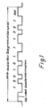
- the information is transmitted in pulse pauses modulated (PPM-coded) serial telegrams each having a start and a stop character Stp and Spp, as shown in FIG. 1, for example, for information 10010111001 with additional 8-bit information.
- PPM-coded serial telegrams each having a start and a stop character Stp and Spp, as shown in FIG. 1, for example, for information 10010111001 with additional 8-bit information.
- the telegrams to be transmitted are assigned to a telemetry frame shown in FIG. 2, which is subdivided into corresponding grid locations in the respective circumstances, here in five grid locations RP1 to RP5 corresponding to five transmission times RS1 to RS5 for the data radio stations MDF.
- Each grid position is followed by an acknowledgment signal time Q1 to Q5, within which the correct receipt of an information telegram is confirmed by the control center.
- This acknowledgment is always given if no transmission time for the mobile radio data stations is specified in the telemetry frame.
- the control center can also send a synchronization sign or a transmission request in order to optimally use the only high-frequency channel available for the transmission.
- the total cycle of the telemetry frame here comprises x seconds and is subdivided into y milliseconds for grid positions RP1 to RP5 and z milliseconds for additional grid positions to be distributed by the control center, that is to say additional transmission time.
- This division of the telemetry frame makes it possible to transmit the different transmission times that occur in practice for the different amounts of data to be transmitted from the individual mobile data radio stations to the central station and vice versa in a time pattern each having the same time window. Fault messages can also be transmitted preferentially during these transmission times.
- the control center sends a synchronization signal SYNC at the beginning of each telemetry frame, which appears here every x seconds.
- the synchronization signal is followed by the five grid positions RP1 or RS1 to RP5 or RS5 for transmissions from the mobile data radio stations, the transmission times of which are shown in line 2 of FIG.
- An electronic cube circuit 16 is present in each radio data station, by means of which at least one of a plurality of available grid positions is stochastically determined.
- the first free or the first free diced grid spaces are used by the radio data station for the transmission of their data information to the control center. Since each data radio station can hear the radio traffic of the other data radio stations belonging to the telemetry frame via its own receiving system, it is easy to determine whether the grid space assigned to it by the dice is currently free. In each grid position, the transmission time is available for the central station to acknowledge the received telegram, see Q 1 to Q 5 in line 1 of FIG. 2.
- FIG. 3 shows the temporal arrangement of a synchronization telegram for RO to Rn grid spaces for the mobile data radio stations.
- the control center sends a synchronization signal SYNC to all mobile data radio stations, which then report with "ready” or “not ready” or with their pending useful information in accordance with the grid positions RO to Rn in the manner described above.
- the control center sends its messages in the time period "A" between two synchronization signals SYNC, cf. Line 2 of Figure 3 (e.g. drive from O to P).
- FIG. 1 A block diagram of the central ZFS is shown schematically in FIG. It comprises a radio communication computer 1 and a program and working memory 3, to which a control unit 2 is superordinate.
- the control center can be connected to other higher-level computers via a serial interface (RS 232C or 20mA current loop).
- the radio communication computer 1 with its microprocessor with program and working memory 3 includes a transmit / receive logic for a half-duplex operation of high frequency.
- the radio communication computer is also connected via an HF interface 4 to an HF transmitting / receiving part 5.
- an antenna switch 6 and an LF modem 8 are also provided.
- the described configuration of the control center makes it possible to work with a low transmitter output power of at most 1 W when connecting up to n mobile data radio stations to the control center.
- multi-antenna operation is provided, which is controlled via the computer by the antenna switch 6 mentioned.
- Several antennas can be connected to the antenna switchover via a cable or other HF transmit / receive parts for better illumination of the driving area in a factory site or within a warehouse.
- the mentioned NF modem enables the connection of several remote sub-centers, to which in turn one or more antennas with an RF transmit / receive part and provided ramp controls as well as a controller for adapting the impedance and the signal adjustment can be connected, so that larger ranges can be achieved in this way.
- Each mobile data radio station has a circuit arrangement shown schematically in FIG. 5 as a block diagram.
- This circuit arrangement comprises an RF transmission / reception part 10, a CPU control with interface 11 (central processing unit) and a control unit 12 which is connected to a memory 13. Furthermore, a display device (display) 14 and an input keyboard 15 are provided.
- the control unit is assigned a so-called electronic cube 16, by means of which one or more grid spaces are called up in a manner known per se from the grid spaces of the telemetry frame available in each case, of which the first unit is called by the control unit free grid spaces for sending an existing information telegram can be occupied. Since each radio data station has an RF receiver, it can determine whether the radio station or radio stations determined by the dice are actually free or whether they are currently transmitting by receiving data radio stations that are currently transmitting.
Landscapes
- Engineering & Computer Science (AREA)
- Computer Networks & Wireless Communication (AREA)
- Signal Processing (AREA)
- Mobile Radio Communication Systems (AREA)
Claims (9)
Priority Applications (3)
| Application Number | Priority Date | Filing Date | Title |
|---|---|---|---|
| EP19860108704 EP0250621B1 (fr) | 1986-06-26 | 1986-06-26 | Méthode de transmission d'informations entre un central radio de données et plusieurs stations de données mobiles sur une seule fréquence porteuse |
| DE8686108704T DE3664030D1 (en) | 1986-06-26 | 1986-06-26 | Method for information transmission between a central data radio station and a plurality of mobile stations on a single carrier frequency |
| GB8710716A GB2192516B (en) | 1986-06-26 | 1987-05-06 | A method of transmitting data between a central data radio station and a number of mobile data radio stations on a single carrier frequency |
Applications Claiming Priority (1)
| Application Number | Priority Date | Filing Date | Title |
|---|---|---|---|
| EP19860108704 EP0250621B1 (fr) | 1986-06-26 | 1986-06-26 | Méthode de transmission d'informations entre un central radio de données et plusieurs stations de données mobiles sur une seule fréquence porteuse |
Publications (2)
| Publication Number | Publication Date |
|---|---|
| EP0250621A1 EP0250621A1 (fr) | 1988-01-07 |
| EP0250621B1 true EP0250621B1 (fr) | 1989-06-14 |
Family
ID=8195223
Family Applications (1)
| Application Number | Title | Priority Date | Filing Date |
|---|---|---|---|
| EP19860108704 Expired EP0250621B1 (fr) | 1986-06-26 | 1986-06-26 | Méthode de transmission d'informations entre un central radio de données et plusieurs stations de données mobiles sur une seule fréquence porteuse |
Country Status (3)
| Country | Link |
|---|---|
| EP (1) | EP0250621B1 (fr) |
| DE (1) | DE3664030D1 (fr) |
| GB (1) | GB2192516B (fr) |
Families Citing this family (6)
| Publication number | Priority date | Publication date | Assignee | Title |
|---|---|---|---|---|
| FR2693862B1 (fr) * | 1992-07-20 | 1994-09-02 | Txcom | Procédé et dispositif de transmission à distance d'informations au moyen d'ondes hertziennes. |
| GB2271691A (en) * | 1992-09-21 | 1994-04-20 | Oconnor P J | Synchronisation of a radio telemetry system |
| KR960002103A (ko) * | 1994-06-02 | 1996-01-26 | 강석군 | 차량정보 송수신장치및 그 처리방법 |
| DE19927845A1 (de) * | 1999-06-18 | 2001-01-04 | Sican Gmbh | Verfahren zur Funkübertragung von Daten und Endgerät hierzu |
| US7792089B2 (en) | 2002-07-31 | 2010-09-07 | Cattron-Theimeg, Inc. | System and method for wireless remote control of locomotives |
| CN107864031A (zh) * | 2017-10-24 | 2018-03-30 | 中国科学院上海技术物理研究所 | 一种适用于m阶ppm调制的单光子通信的同步方法 |
Family Cites Families (6)
| Publication number | Priority date | Publication date | Assignee | Title |
|---|---|---|---|---|
| DE2351013B2 (de) * | 1973-10-11 | 1977-08-25 | Licentia Patent-Verwaltungs-Gmbh, 6000 Frankfurt | Nachrichtenuebermittlungssystem |
| DE2362765A1 (de) * | 1973-12-17 | 1975-06-19 | Battelle Institut E V | Verfahren zur funkfernsteuerung einer groesseren anzahl voneinander unabhaengiger geraete ueber einen gemeinsamen hochfrequenz-kanal |
| DE2812009C2 (de) * | 1978-03-18 | 1984-08-02 | Standard Elektrik Lorenz Ag, 7000 Stuttgart | Nachrichtenübertragungssystem |
| GB2063011B (en) * | 1979-11-09 | 1983-10-12 | Philips Electronic Associated | Information transmission system |
| US4414661A (en) * | 1981-07-02 | 1983-11-08 | Trancom Ab | Apparatus for communicating with a fleet of vehicles |
| DE3304451C1 (de) * | 1983-02-09 | 1990-02-15 | Siemens AG, 1000 Berlin und 8000 München | Verfahren und Einrichtung zur bidirektionalen Informationsübertragung zwischen einer stationären Hauptstation und mehreren mobilen Unterstationen |
-
1986
- 1986-06-26 EP EP19860108704 patent/EP0250621B1/fr not_active Expired
- 1986-06-26 DE DE8686108704T patent/DE3664030D1/de not_active Expired
-
1987
- 1987-05-06 GB GB8710716A patent/GB2192516B/en not_active Expired - Fee Related
Also Published As
| Publication number | Publication date |
|---|---|
| EP0250621A1 (fr) | 1988-01-07 |
| GB2192516A (en) | 1988-01-13 |
| GB2192516B (en) | 1990-11-28 |
| DE3664030D1 (en) | 1989-07-20 |
| GB8710716D0 (en) | 1987-06-10 |
Similar Documents
| Publication | Publication Date | Title |
|---|---|---|
| EP0850547B1 (fr) | Procede de transmission de paquets de donnees entre des stations mobiles et des stations de base dans des systemes radio mobiles fonctionnant par multiplexage dans le temps | |
| DE4335832B4 (de) | Funksteuersystem sowie Verfahren zum sicheren drahtlosen Fernsteuern | |
| EP3427538B1 (fr) | Systeme de communication industriel pouvant fonctionner de maniere redondante, son procede de fonctionnement et poste d'abonné radio | |
| EP0035731A2 (fr) | Procédé et dispositif pour le transfert de signaux de données | |
| EP0250621B1 (fr) | Méthode de transmission d'informations entre un central radio de données et plusieurs stations de données mobiles sur une seule fréquence porteuse | |
| EP0192120B2 (fr) | Système et dispositif de transmission de données pour commande à distance | |
| DE69433313T2 (de) | Multi-Master Überwachungssystem | |
| EP0613259B1 (fr) | Dispositif pour communication continue dans un système de transmission à câble rayonnant | |
| EP0443438B1 (fr) | Procédé et dispositif pour alerter les personnes dans la zone de voie ferrée sur un canal de communication à haute fréquence | |
| EP3522605A1 (fr) | Système de radiocommunication pour un système d'automatisation industrielle et procédé de fonctionnement d'un système de radiocommunication | |
| EP0326630B1 (fr) | Procédé de transmission de signaux de télécommande sur une seule fréquence porteuse entre émetteurs et récepteurs autonomes fonctionnant en multiplexage par répartition dans le temps et dispositif pour la mise en oeuvre du procédé | |
| DE2264085C2 (de) | Fernwirkanlage mit wenigstens einer Hauptzentrale, der ein Hauptnetz zugeordnet ist | |
| EP0797818B1 (fr) | Procede et dispositif de radiocommunication dans des systemes de guidage de la circulation routiere | |
| DE19733765A1 (de) | Verfahren zur Kommunikation zwischen einem im Bereich einer Schienenstrecke angeordneten Feldelement und einer zentralen Überwachungseinheit sowie Kommunikationssystem und Sendeempfangseinheit hierfür | |
| DE102020005856A1 (de) | Verfahren zum Betreiben einer technischen Anlage und technische Anlage | |
| DE19624019B4 (de) | Vorrichtung und Verfahren zur mobilen Kommunikation von Arbeitsmaschinen | |
| EP0235371B1 (fr) | Système d'appel individuel et sa méthode de commande | |
| DE19548650A1 (de) | Verfahren zum Betrieb eines mobilen, funkgesteuerten Alarmsystems | |
| DE3743755C2 (de) | Verfahren und Einrichtung zur sicheren Übertragung von Blockinformation zwischen Spurplanstellwerken | |
| WO2001006802A1 (fr) | Terminal de communication et procede pour comprimer et/ou decomprimer des messages reçus ou a envoyer | |
| DE2303989A1 (de) | Zweiweg-nachrichtenuebertragungssystem | |
| DE19857005A1 (de) | Verfahren und Vorrichtung zum Überwachen eines Ausgangssignals eines Bauteils einer Vermittlungseinrichtung | |
| EP3252735B1 (fr) | Procédé de transmission de communication vocale | |
| DE3729133C1 (de) | Schaltungsanordnung fuer den Betrieb von Bedien- oder Abfrageplaetzen an zentral gesteuerten Fernsprechvermittlungsanlagen,insbesondere Makler-Vielfachanlagen | |
| DE10136757C1 (de) | Selektives Funkübertragungssystem |
Legal Events
| Date | Code | Title | Description |
|---|---|---|---|
| PUAI | Public reference made under article 153(3) epc to a published international application that has entered the european phase |
Free format text: ORIGINAL CODE: 0009012 |
|
| 17P | Request for examination filed |
Effective date: 19870408 |
|
| AK | Designated contracting states |
Kind code of ref document: A1 Designated state(s): BE DE FR |
|
| 17Q | First examination report despatched |
Effective date: 19880414 |
|
| GRAA | (expected) grant |
Free format text: ORIGINAL CODE: 0009210 |
|
| AK | Designated contracting states |
Kind code of ref document: B1 Designated state(s): BE DE FR |
|
| REF | Corresponds to: |
Ref document number: 3664030 Country of ref document: DE Date of ref document: 19890720 |
|
| ET | Fr: translation filed | ||
| PLBE | No opposition filed within time limit |
Free format text: ORIGINAL CODE: 0009261 |
|
| STAA | Information on the status of an ep patent application or granted ep patent |
Free format text: STATUS: NO OPPOSITION FILED WITHIN TIME LIMIT |
|
| 26N | No opposition filed | ||
| PGFP | Annual fee paid to national office [announced via postgrant information from national office to epo] |
Ref country code: DE Payment date: 19980514 Year of fee payment: 13 |
|
| PGFP | Annual fee paid to national office [announced via postgrant information from national office to epo] |
Ref country code: FR Payment date: 19980617 Year of fee payment: 13 |
|
| PGFP | Annual fee paid to national office [announced via postgrant information from national office to epo] |
Ref country code: BE Payment date: 19980623 Year of fee payment: 13 |
|
| PG25 | Lapsed in a contracting state [announced via postgrant information from national office to epo] |
Ref country code: FR Free format text: THE PATENT HAS BEEN ANNULLED BY A DECISION OF A NATIONAL AUTHORITY Effective date: 19990630 Ref country code: BE Free format text: LAPSE BECAUSE OF NON-PAYMENT OF DUE FEES Effective date: 19990630 |
|
| BERE | Be: lapsed |
Owner name: THEIMEG ELEKTRONIKGERATE G.M.B.H. & CO. K.G. Effective date: 19990630 |
|
| PG25 | Lapsed in a contracting state [announced via postgrant information from national office to epo] |
Ref country code: DE Free format text: LAPSE BECAUSE OF NON-PAYMENT OF DUE FEES Effective date: 20000503 |
|
| REG | Reference to a national code |
Ref country code: FR Ref legal event code: ST |