EP0250621B1 - Method for information transmission between a central data radio station and a plurality of mobile stations on a single carrier frequency - Google Patents
Method for information transmission between a central data radio station and a plurality of mobile stations on a single carrier frequency Download PDFInfo
- Publication number
- EP0250621B1 EP0250621B1 EP19860108704 EP86108704A EP0250621B1 EP 0250621 B1 EP0250621 B1 EP 0250621B1 EP 19860108704 EP19860108704 EP 19860108704 EP 86108704 A EP86108704 A EP 86108704A EP 0250621 B1 EP0250621 B1 EP 0250621B1
- Authority
- EP
- European Patent Office
- Prior art keywords
- data
- station
- transmission
- central
- radio
- Prior art date
- Legal status (The legal status is an assumption and is not a legal conclusion. Google has not performed a legal analysis and makes no representation as to the accuracy of the status listed.)
- Expired
Links
Images


Classifications
-
- H—ELECTRICITY
- H04—ELECTRIC COMMUNICATION TECHNIQUE
- H04B—TRANSMISSION
- H04B7/00—Radio transmission systems, i.e. using radiation field
- H04B7/24—Radio transmission systems, i.e. using radiation field for communication between two or more posts
- H04B7/26—Radio transmission systems, i.e. using radiation field for communication between two or more posts at least one of which is mobile
- H04B7/2643—Radio transmission systems, i.e. using radiation field for communication between two or more posts at least one of which is mobile using time-division multiple access [TDMA]
Description
Die Erfindung betrifft ein Verfahren zur Übertragung von Informationen zwischen einer Datenfunkzentrale und einer Vielzahl von mobilen Datenfunkstationen auf einer einzigen Trägerfrequenz, wobei Datenfunkzentrale und mobile Datenfunkstationen Sende- und Empfangseinrichtungen aufweisen.The invention relates to a method for transmitting information between a data radio center and a plurality of mobile data radio stations on a single carrier frequency, data radio center and mobile data radio stations having transmitting and receiving devices.
Solche Verfahren werden insbesondere zum Fernsteuern von Lokomotiven, Entladeeinrichtungen und ähnlichen sich bewegenden Objekten verwendet; vgl. z.B. DE-B 27 56 613.Such methods are used in particular for remote control of locomotives, unloading devices and similar moving objects; see. e.g. DE-B 27 56 613.
Zur Überwachung der Fahrrouten von Omnibussen ist es bekannt (DE-A 2 812 009), eine Kommunikation zwischen einer festen Hauptstation und mehreren beweglichen Stationen in der Weise herzustellen, daß innerhalb eines sich wiederholenden festen Zeitrahmens mit einer Anzahl von gleichlangen Zeitschlitzen in bestimmten dieser Zeitschlitze Synchronisierimpulse von der Hauptstation und in bestimmten den einzelnen beweglichen Stationen festzugeordneten anderen Zeitschlitzen Datentelegramme von den beweglichen Stationen ausgesendet werden und im festen Zeitrahmen ferner Zeitschlitze für Datentelegramme der Hauptstation an die beweglichen Stationen und Zeitschlitze für das Belegen durch die beweglichen Stationen vorzusehen, um Notrufe und andere dringende Meldungen und etwa erforderlich werdende Antwortmeldungen absetzen zu können, wobei solche Meldungen bis zur Quittierung durch die angesprochene Hauptstation stochastisch wiederholt werden können und wobei die freien Zeitschlitze nur dann belegt werden können, wenn eine Freiprüfung ergeben hat, daß sie nicht von anderen beweglichen Stationen belegt worden sind.For monitoring the driving routes of buses, it is known (DE-A 2 812 009) to establish communication between a fixed main station and several moving stations in such a way that within a repeating fixed time frame with a number of equally long time slots in certain of these time slots Synchronization pulses from the main station and in certain other time slots assigned to the individual mobile stations, data telegrams are sent out by the mobile stations and, in the fixed time frame, time slots for data telegrams from the main station to the mobile stations and time slots for occupancy by the mobile stations to provide emergency calls and others to be able to issue urgent messages and any response messages that may become necessary, such messages being able to be repeated stochastically until acknowledgment by the main station addressed and the free time slots only occupying them t can be obtained if a free test has shown that they have not been used by other mobile stations.
Zwar ist es hierdurch möglich, einen gegenseitigen Nachrichtenaustausch zwischen Haupt- und beweglichen Stationen durchzuführen und dabei auch zusätzliche Meldungen, Anfragen oder Notrufe sowie die erforderlich werdenden Antwortmeldungen zu übertragen. Da jedoch ein Zeitrahmen bestimmter Länge vorgegeben ist, ist auch die Anzahl der beweglichen Stationen festgelegt und kann nicht beliebig erweitert werden. Nichtbenutzte Zeitschlitze bleiben ungenützt, was die Übertragungszeit nachteilig beeinflußt, da ungenützte Zeitschlitze verlorene Übertragungskapazität bedeuten. Zeitschlitze vorgegebener Länge erfordern aber auch Datentelegramme vorgegebener Länge bzw. Datenmenge, so daß Datentelegramme davon abweichender Länge die Zeitschlitze entweder nicht völlig ausfüllen oder ihre Datenmenge nicht übertragen werden kann. Außerdem können die beweglichen Stationen nur in den zugeordneten Zeitschlitzen und nur in Sonderfällen in freien Zeitschlitzen senden, die wiederum nur an bestimmten Stellen des festen Zeitrahmens vorgesehen sind, so daß oft nicht alle Informationen innerhalb eines Sendezyklus ausgetauscht werden können.This makes it possible to carry out a mutual exchange of messages between the main and moving stations and also to transmit additional messages, inquiries or emergency calls as well as the response messages that are required. However, since a time frame of a certain length is specified, the number of moving stations is also fixed and cannot be expanded at will. Unused time slots remain unused, which adversely affects the transmission time, since unused time slots mean lost transmission capacity. Time slots of a predetermined length also require data telegrams of a predetermined length or amount of data, so that data telegrams of a different length either do not completely fill the time slots or their amount of data cannot be transmitted. In addition, the movable stations can only transmit in the assigned time slots and only in special cases in free time slots, which in turn are only provided at certain points in the fixed time frame, so that often not all information can be exchanged within one transmission cycle.
Est ist auch bekannt, von einer Leitstelle aus über Sprechfunk die Fahrrouten einer Vielzahl von Fahrzeugen, wie z.B. Taxi oder Lastkraftwagen zu koordinieren, um so deren Einsatz zu optimieren.It is also known to control the driving routes of a large number of vehicles, e.g. Coordinate taxis or trucks to optimize their use.
Allen diesen Anwendungen liegt die allgemeine Erkenntnis zugrunde, daß die Wirtschaftlichkeit eines Produktions- oder Transportbetriebes oder eines Handelsunternehmens im wesentlichen durch einen rationellen Materialfluß bestimmt wird, wobei erst bei einer hohen Transparenz im Informationsfluß innerhalb der Abläufe zwischen Lager und Betrieb die Transportleistungen ohne den Umweg über die Verarbeitung kostenintensiver Belege optimiert werden können.All of these applications are based on the general knowledge that the economic viability of a production or transport company or a trading company is essentially determined by a rational material flow, whereby only with a high level of transparency in the information flow within the processes between warehouse and company, the transport services without the detour the processing of expensive documents can be optimized.
Voraussetzung hierfür ist, das Informationen schnell bekannt werden, um es zu ermöglichen, rechtzeitig über Maßnahmen zu entscheiden, welche Transportabläufe in welcher Reihenfolge und Form vorrangig durchgeführt werden müssen. Informationen über bereits erfolgte Transportvorgänge haben hierbei nur noch statistischen Wert.The prerequisite for this is that information becomes known quickly so that it is possible to decide on measures in good time as to which transport processes, in which order and form, must be carried out with priority. Information about transport processes that have already taken place is only of statistical value.
Die funktechnische Übermittlung solcher Informationen erfolgte bisher über die genannten Sprechfunksysteme. Solche Sprechfunksysteme arbeiten jedoch nicht störungsfrei und auch nicht schnell genug, um in einem Rechner zur Auswertung zur Verfügung zu stehen. Durch die vielen Sprechfunksysteme, die in einem Großbetrieb gleichzeitig in verschiedenen Frequenzbereichen betrieben werden, wie Personenrufanlagen, mobile Handsprechfunkgeräte für Feuerwehr, Werkschutz und ähnliches, wird eine schnelle störungsfreie Übertragung solcher Informationen unmöglich gemacht. Darüber hinaus müssen über Sprechfunk übertragene Informationen von Hand in den Computer eingegeben werden, was ebenfalls zeitaufwendig ist. Funksprechgeräte mit digitalisierter Sprachübertragung sind bisher auf dem Markt nicht erhältlich.The radio transmission of such information has so far been carried out via the aforementioned radio systems. However, such radio systems do not work properly and not fast enough to be available in a computer for evaluation. The many voice radio systems that are operated simultaneously in a large company in different frequency ranges, such as paging systems, mobile walkie-talkies for fire services, security and the like, make fast, interference-free transmission of such information impossible. In addition, information transmitted via voice radio must be entered into the computer by hand, which is also time-consuming. Two-way radios with digitized voice transmission are not yet available on the market.
Beide vorerwähnten Verfahren sind daher für eine zeitoptimierte Übertragung einer Vielzahl von Informationen mit stark unterschiedlicher Datenmenge zwischen einer Zentrale und mobilen Datenfunkstationen und vis versa wenig geeignet.Both of the above-mentioned methods are therefore unsuitable for time-optimized transmission of a large amount of information with a very different amount of data between a central office and mobile data radio stations and vis versa.
Der Erfindung liegt daher die Aufgabe zugrunde, ein neues Verfahren und eine Schaltungsanordnung zur Durchführung des Verfahrens zu schaffen das besser als die bisherigen Verfahren für eine schnelle wechselseitige Übertragung von Informationen auf einer einzigen Trägerfrequenz zwischen einer Zentrale und mobilen Datenfunkstationen geeignet ist unter Berücksichtigung unterschiedlicher Datenmengen innerhalb eines vorgegebenen Telemetrierahmens.The invention is therefore based on the object of creating a new method and a circuit arrangement for carrying out the method, which is better than the previous methods for fast mutual transmission of information on a single carrier frequency between a central and mobile data radio stations, taking into account different amounts of data within of a given telemetry frame.
Diese Aufgabe ist gemäß der Erfindung für das Verfahren durch die kennzeichnenden Merkmale des Patentanspruchs 1, für die Anordnung zur Durchführung des Verfahrens durch die kennzeichnenden Merkmale des Patentanspruchs 6 gelöst.This object is achieved according to the invention for the method by the characterizing features of
Weitere Merkmale der Erfindung ergeben sich aus den Unteransprüchen.Further features of the invention emerge from the subclaims.
Die Informationsübertragung zwischen der Zentrale und den mobilen Datenfunkstationen erfolgt also innerhalb eines eine Vielzahl von Rasterplätzen umfassenden Telemetrierahmens mit einem in Abhängigkeit der Anzahl der Rasterplätze zu wählenden Zeitraster, der durch die Zentrale durch Senden von Synchronisationssignalen für alle Datenfunkstationen synchronisiert wird. Alle zu übertragenden Informationen werden in kodierten seriellen Telegrammen gesendet, die jeweils mit einem Start-Zeichen beginnen und mit einem StoppZeichen enden, so daß der jeweilige Empfänger eine eindeutige Telegrammerkennung vornehmen kann. Die zur Telegrammübertragung zur Verfügung stehenden Rasterplätze werden von den Datenfunkterminals stochastisch verteilt mit Informationstelegrammen belegt, eine Telegrammübertragung auf einem oder mehreren stochastisch belegten Rasterplatz oder -plätzen erfolgt nur dann, wenn dieser Rasterplatz oder -plätze durch fehlenden Empfang von Informationen dritter Datenfunkstationen von der sendebereiten Datenfunkstation als unbelegt erkannt wird. Ist ein stochastisch gewählter Rasterplatz belegt, so werden ein oder n- andere freie Rasterplätze stochastisch belegt. Der Zentrale ist innerhalb des Telemetrierahmens mindestens ein Rasterplatz zugeordnet, der zum Senden von Informationen von der Zentrale zu den Datenfunkstationen nutzbar ist oder aber von der Zentrale einer bestimmten Datenfunkstation für eine Informationsübertragung zur Zentrale zugeordnet werden kann. Jede Informationsübertragung zwischen Datenfunkstationen und Zentrale wird von der Zentrale durch eine Funksignal bestätigt, für das jeweils ein Quittungsplatz an Ende jedes Rasterplatzes vorgesehen ist.The information transmission between the control center and the mobile data radio stations thus takes place within a telemetry frame comprising a plurality of grid positions with a time grid to be selected depending on the number of grid positions and which is synchronized by the control center by sending synchronization signals for all data radio stations. All closed Transmitting information is sent in coded serial telegrams, each beginning with a start character and ending with a stop character, so that the respective recipient can make a clear telegram identification. The raster locations available for telegram transmission are stochastically distributed by the data radio terminals with information telegrams; a telegram transmission to one or more stochastically allocated raster locations or locations only takes place if this raster location or locations is not received by third-party radio stations from the ready-to-transmit radio station is recognized as unoccupied. If a stochastically selected grid space is occupied, one or n other free grid spaces are stochastically occupied. The center is assigned at least one grid space within the telemetry frame, which can be used to send information from the center to the data radio stations or can be assigned by the center to a specific data radio station for information transmission to the center. Each transmission of information between radio data stations and the control center is confirmed by the control center by means of a radio signal, for which a receipt space is provided at the end of each grid position.
Die Übertragung der Daten erfolgt mit einer durchschnittlichen Sendegeschwindigkeit von minimal 1200 Bit/sec, die je nach verwendeten HF-Bauteilen bis auf 7200 Bit/sec erhöht werden kann. Zur Erhöhung der Übertragungssicherheit ist jedem Telegramm nach der eigentlichen Nutzinformation eine Zusatzinformation von mindestens 8 Bit angehängt, die sicherstellt, daß zwei beliebige Telegramme sich in mindestens 4 Bit unterscheiden, mit anderen Worten, für die Telegrammsicherung ist eine Hamming-Distanz von mindestens D = 4 vorgesehen. Zur weiteren Erhöhung der Übertragungssicherheit sind jeder mobilen Datenfunkstation ein oder mehrere Rasterplätze innerhalb des Telemetrierahmens zugeordnet, so daß eine stochastische Belegung eines oder mehrerer Rasterplätze durch eine Datenfunkstation durch ein- oder mehrmaliges elektronisches Würfeln erfolgen kann, wobei von den gewürfelten Rasterplätzen der oder die jeweils freien Rasterplätze für die Informationsübertragung zwischen Datenfunkstationen und Zentrale benutzt wird. Durch das elektronische Würfeln wird sichergestellt, daß jeder mobilen Datenfunkstation ein freies Zeitraster zugeordnet werden kann, innerhalb dessen die einzelnen Meldungen der mobilen Datenfunkstation in der Zentrale sicher empfangen werden können. Sollten wider Erwarten ein oder mehrmals Überschneidungen von zu belegenden und belegten Rasterplätzen auftreten, so können trotzdem keine Meldungen verloren gehen, da innerhalb des Telemetrierahmens Sendezeiten für das Quittieren einer empfangenden Information vorgesehen sind, so daß die jeweilige Datenfunkstation die vollständige Informationsübertragung erkennt. Durch den Empfang anderer gerade sendender Datenfunkstationen "hört" also die sendebereite Datenfunkstation, ob der ihr durch das "Würfeln" zugeordnete Rasterplatz des Telemetrierahmens frei ist oder nicht.The data is transmitted at an average transmission speed of at least 1200 bit / sec, which can be increased to 7200 bit / sec depending on the RF components used. To increase the transmission security, additional information of at least 8 bits is attached to each telegram after the actual user information, which ensures that any two telegrams differ in at least 4 bits, in other words, a Hamming distance of at least D = 4 is for the telegram protection intended. To further increase the security of transmission, each mobile radio data station is assigned one or more grid positions within the telemetry frame, so that a stochastic assignment of one or more grid positions by a data radio station can take place by one or more electronic dice, the grid space or cubes being vacated Grid spaces for the transmission of information between radio stations and headquarters is used. The electronic dicing ensures that a free time grid can be assigned to each mobile data radio station, within which the individual messages from the mobile data radio station can be securely received at the center. If, contrary to expectations, one or more overlaps occur between occupied and occupied grid spaces, no messages can still be lost, since within the telemetry frame transmission times are provided for acknowledging received information, so that the respective radio data base recognizes the complete transmission of information. By receiving other currently transmitting data radio stations, the data radio station ready to send "hears" whether the grid space of the telemetry frame assigned to it by the "dice" is free or not.
Innerhalb des Zeitrasters werden alle Nutzdaten, wie z.B. Auftrags-Paletten- und ähnliche Kenn-Nummern, Stör- und Funktionsmeldungen, sowie Anforderung für eine längere Sendezeit zur Übertragung längerer Telegramme an die Zentrale übertragen. Wie bereits erwähnt, wird jede Sendung durch ein Quittungssignal seitens der Zentrale bestätigt. Die Wahl der Rasterplätze ist ferner so getroffen, daß nach Ablauf der Zeit für die Meldungen der Datenfunkstationen der Zentrale eine eigene Sendezeit zur Verfügung steht. Die im Telemetrierahmen für die Zentrale vorgesehene Sendezeit befindet sich vorzugsweise in den Pausen zwischen zwei Informationstelegrammen. Dies hat den Vorteil, daß die Zentrale immer den aktuellen Stand der in Funkkontakt stehenden erreichbaren mobilen Datenfunkstationen erfragen kann. Ein weiterer Vorteil ist darin zu sehen, daß durch die stochastische Belegung der Rasterplätze durch eine Datenfunkstation in aller Regel mindestens eine Nachricht von der Datenfunkstation zur Zentrale innerhalb eines Sendezyklus gesendet werden kann. Bei fester Zuordnung eines Rasterplatzes für je eine Datenfunkstation besteht die Gefahr, daß eine Nachricht von einer Datenfunkstation zur Zentrale erst nach mehreren Zyklen möglich ist, da je nach Lage und Ausbreitungsbedingungen sowie Sendetoleranzen mehrere Datenfunkstationen während des Betriebs sich überlagern können. Durch die stochastische Belegung erfolgt also eine zeitliche Entzerrung. Schließlich kann durch die Quittungssignale der Zentrale der einzige Hochfrequenzkanal, der zur Informationsübertragung zur Verfügung steht und für beide Senderichtungen benutzt werden muß, exakt zeitlich aufgeteilt werden. Die Zentrale erkennt an der Kennummer (Adresse), mit welcher der Datenfunkstationen Funkkontakt bestanden hat.All user data, e.g. Transfer order pallet and similar identification numbers, fault and function messages, as well as request for a longer transmission time for the transmission of longer telegrams to the control center. As already mentioned, each consignment is confirmed by an acknowledgment signal from the control center. The choice of grid positions is also made so that after the time for the reports from the data radio stations of the central station a separate transmission time is available. The transmission time provided for the center in the telemetry frame is preferably in the pauses between two information telegrams. This has the advantage that the control center can always inquire about the current status of the mobile data radio stations that can be reached in radio contact. Another advantage can be seen in the fact that the stochastic allocation of the grid positions by a radio data transmission station can generally send at least one message from the radio data transmission station to the control center within a transmission cycle. With a fixed assignment of a grid space for each radio data station, there is a risk that a message from a data radio station to the control center is only possible after several cycles, since depending on the location and propagation conditions as well as transmission tolerances, several data radio stations can overlap during operation. The stochastic assignment therefore results in a time equalization. Finally, the only high-frequency channel that is available for information transmission and that must be used for both transmission directions can be divided exactly in time by the acknowledgment signals from the control center. The control center recognizes from the identification number (address) with which the radio data base has been in radio contact.
Die Vorteile des erfindungsgemäßen Verfahrens sind ferner darin zu sehen, daß insbesondere bei seinem Einsatz in der Lagerverwaltung infolge der zeitoptimierten Übertragung aller vorhandenen Informationen zwischen Zentrale und mobilen Datenfunkstationen ohne den Umweg über geschriebene Belege die Lagerbestände wesentlich gesenkt, ein schnellerer Lagerumschlag erreicht und damit die Kapitalbindung durch das Lager wesentlich verringert wird. Dies gilt auch für die eingesetzten Betriebsmittel, wie Fahrzeuge und Personal. Auch können Leistungsspitzen einfacher als bisher bewältigt werden, ohne daß es zu Fehlleitungen kommt.The advantages of the method according to the invention can also be seen in the fact that, in particular when it is used in warehouse management, due to the time-optimized transmission of all available information between the central office and mobile data radio stations without the detour via written receipts, the inventories are reduced significantly, a faster inventory turnover is achieved and thus the capital commitment is significantly reduced by the camp. This also applies to the equipment used, such as vehicles and personnel. Power peaks can also be dealt with more easily than before without false leads.
Die Erfindung ist nachfolgend anhand eines in der Zeichnung dargestellten Ausführungsbeispieles beschrieben. Es zeigen:
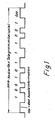
Figur 1 schematisch ein PPM-kodiertes Telegramm für den Informationsinhalt 100 10111001,Figur 2 ein Diagramm des Zeitrasters der Rasterplätze eines Telemetrierahmens für eine Zentrale und n mobile Datenfunkstationen,- Figur 3 die zeitliche Anordnung des Telemetrie- rahmens,
Figur 4 ein Blockschaltbild der steuernden Funkzentrale undFigur 5 ein Blockschaltbild einer mobilen Datenfunkstation.
- 1 schematically shows a PPM-coded telegram for the information content 100 10111001,
- FIG. 2 shows a diagram of the time grid of the grid positions of a telemetry frame for a central office and n mobile data radio stations,
- FIG. 3 shows the temporal arrangement of the telemetry frame,
- Figure 4 is a block diagram of the controlling radio center and
- Figure 5 is a block diagram of a mobile radio station.
Als Anwendungsbeispiel für das nachfolgend beschriebene Verfahren zur Datenübertragung zwischen einer Zentrale ZFS und mobilen Datenfunkstationen MDF1 bis MDFn ist ein Material-Transportsystem gewählt, ohne jedoch die Erfindung hierauf zu beschränken.A material transport system is selected as an application example for the method described below for data transmission between a central ZFS and mobile data radio stations MDF1 to MDFn, but without restricting the invention thereto.
Alle Informationen, die zwischen der Zentrale und den Datenfunkstationen und vice versa auszutauschen sind, werden auf einer einzigen Trägerfrequenz drahtlos seriell übertragen. Hierzu werden die Informationen in Impulspausen modulierten (PPM-kodiert) seriellen, je ein Start- und ein StoppZeichen Stp und Spp aufweisende Telegramme überführt, wie dies Figur 1 beispielsweise für die Information 10010111001 mit einr 8-Bit-Zusatzinformation zeigt. Die zu sendenden Telegramme sind einem in Figur 2 dargestellten Telemetrierahmen zugeordnet, der in den jeweiligen Gegebenheiten entsprechende Rasterplätze unterteilt ist, hier in fünf Rasterplätze RP1 bis RP5 entsprechend fünf Sendezeiten RS1 bis RS5 für die Datenfunkstationen MDF.All information to be exchanged between the control center and the data radio stations and vice versa is wirelessly transmitted serially on a single carrier frequency. For this purpose, the information is transmitted in pulse pauses modulated (PPM-coded) serial telegrams each having a start and a stop character Stp and Spp, as shown in FIG. 1, for example, for information 10010111001 with additional 8-bit information. The telegrams to be transmitted are assigned to a telemetry frame shown in FIG. 2, which is subdivided into corresponding grid locations in the respective circumstances, here in five grid locations RP1 to RP5 corresponding to five transmission times RS1 to RS5 for the data radio stations MDF.
Jedem Rasterplatz ist eine Quittungssignalzeit Q1 bis Q5 nachge ordnet, innerhalb der der richtige Empfang eines Informationstelegramms durch die Zentrale bestätigt wird. Diese Quittierung erfolgt immer dann, wenn im Telemetrierahmen keine Sendezeit für die mobilen Datenfunkstationen vorgegeben sind. Innerhalb dieser Zeit kann aber auch die Zentrale ein Synchronisationszeichen oder eine Sendeaufforderung absenden, um so den einzigen für die Übertragung vorhandenen Hochfrequenzkanal optimal auszunutzen.Each grid position is followed by an acknowledgment signal time Q1 to Q5, within which the correct receipt of an information telegram is confirmed by the control center. This acknowledgment is always given if no transmission time for the mobile radio data stations is specified in the telemetry frame. Within this time, however, the control center can also send a synchronization sign or a transmission request in order to optimally use the only high-frequency channel available for the transmission.
Schließlich folgt ein Rasterplatz Q 7 als normale Sendezeit für die Zentrale, die diese Sendezeit bei Bedarf einer Datenfunkstation zuordnen kann. Am Ende des Telemetrierrahmens folgt nochmals ein Rasterplatz Q 9 für das von der Zentrale aus zu sendende notwendige Quittungssignal.Finally, there is a grid position Q 7 as the normal transmission time for the control center, which can assign this transmission time to a radio data base if required. At the end of the telemetry frame there is again a grid space Q 9 for the necessary acknowledgment signal to be sent from the control center.
Der Gesamtzyklus des Telemetrie-Rahmens umfaßt hier x Sekunden und ist unterteilt in y Millisekunden für die Rasterplätze RP1 bis RP5 und z Millisekunden für zusätzliche von der Zentrale zu verteilende Rasterplätze, also zusätzliche Sendezeit.The total cycle of the telemetry frame here comprises x seconds and is subdivided into y milliseconds for grid positions RP1 to RP5 and z milliseconds for additional grid positions to be distributed by the control center, that is to say additional transmission time.
Durch diese Einteilung des Telemetrierahmens ist es möglich, die in der Praxis auftretenden unterschiedlichen Sendezeiten für die zu übertragenden unterschiedlichen Datenmengen der einzelnen mobilen Datenfunkstationen zur Zentrale und vice versa in jeweils gleiche Zeitfenster aufweisenden Zeitraster befehlen zu übertragen. Auch können während dieser Sendezeiten Störmeldungen bevorzugt übertragen werden.This division of the telemetry frame makes it possible to transmit the different transmission times that occur in practice for the different amounts of data to be transmitted from the individual mobile data radio stations to the central station and vice versa in a time pattern each having the same time window. Fault messages can also be transmitted preferentially during these transmission times.
Wie aus Figur 2 ferner ersichtlich ist, sendet die Zentrale zu Beginn eines jeden Telemetrierahmens ein Synchronisationssignal SYNC, das hier alle x Sekunden erscheint. Dem Synchronisationssignal folgen die fünf Rasterplätze RP1 bzw. RS1 bis RP5 bzw. RS5 für Sendungen der mobilen Datenfunkstationen, deren Sendezeiten in Zeile 2 der Figur 2 dargestellt sind.As can also be seen from FIG. 2, the control center sends a synchronization signal SYNC at the beginning of each telemetry frame, which appears here every x seconds. The synchronization signal is followed by the five grid positions RP1 or RS1 to RP5 or RS5 for transmissions from the mobile data radio stations, the transmission times of which are shown in
In jeder Datenfunkstation ist eine elektronische Würfelschaltung 16 vorhanden,durch die mindestens einer von mehreren zur Verfügung stehenden Rasterplätzen stochastisch bestimmt wird. Der erste freie bzw. die ersten freien gewürfelten Rasterplätze werden von der Datenfunkstation für die Sendung ihrer Dateninformation zur Zentrale benutzt. Da jede Datenfunkstation über ihre eigene Empfangsanlage den Funkverkehr der anderen zum Telemetrierahmen gehörenden Datenfunkstationen hören kann, ist es einfach festzustellen, ob der ihr durch das Würfeln zugewiesene Rasterplatz gerade frei ist. In jedem Rasterplatz steht Sendezeit für das Quittieren des empfangenen Telegramms durch die Zentrale zur Verfügung, siehe Q 1 bis Q 5 in Zeile 1 der Figur 2.An
In Figur 3 ist die zeitliche Anordnung eines Synchronisationstelegramms für RO bis Rn Rasterplätze für die mobilen Datenfunkstationen dargestellt. Die Zentrale sendet am Anfang jedes Telemetrierahmens ein Synchronisationssignal SYNC an alle mobilen Datenfunkstationen, die sich dann mit "bereit" oder "nicht bereit" oder mit ihrer anstehenden Nutzinformation gemäß den Rasterplätzen RO bis Rn nacheinander in der vorstehend beschriebenen Weise melden. Die Zentrale sendet ihre Meldungen in den Zeitbereichen "A" zwischen zwei Synchronisationssignalen SYNC, vgl. Zeile 2 der Figur 3, (z.B.: Fahre von O nach P).FIG. 3 shows the temporal arrangement of a synchronization telegram for RO to Rn grid spaces for the mobile data radio stations. At the beginning of each telemetry frame, the control center sends a synchronization signal SYNC to all mobile data radio stations, which then report with "ready" or "not ready" or with their pending useful information in accordance with the grid positions RO to Rn in the manner described above. The control center sends its messages in the time period "A" between two synchronization signals SYNC, cf.
In Figur 4 ist ein Blockschaltbild der Zentrale ZFS schematisch dargestellt. Sie umfaßt einen Funkkommunikationsrechner 1 und einen Programm-und Arbeitsspeicher 3, denen eine Steuereinheit 2 übergeordnet ist. Über eine serielle Schnittstelle (RS 232C oder 20mA Stromschleife) ist die Zentrale mit weiteren übergeordneten Rechnern zu verbinden. Zum Funkkommunikationsrechner 1 mit seinem Mikroprozessor mit Programm und Arbeitsspeicher 3 gehört eine Sende-/Empfangslogik für einen Halbduplex-Betrieb der Hochfreuenz. Der Funkkommunikationsrechner ist ferner über ein HF-Interface 4 mit einem HF-Sende-/Empfangsteil 5 verbunden. Schließlich sind noch eine Antennenumschaltung 6 und ein NF-Modem 8 vorgesehen. Durch die beschriebene Ausbildung der Zentrale wird ermöglicht, daß bei einem Anschluß von bis n mobilen Datenfunkstationen an die Zentrale mit einer geringen Senderausgangsleistung von maximal 1 W gearbeitet werden kann. Um bei dieser geringen Ausgangsleistung bessere Reichweiten erzielen zu zu können, ist ein Mehrantennenbetrieb vorgesehen, der über den Rechner durch die genannte Antennenumschaltung 6 angesteuert wird. An die Antennenumschaltung können mehrere Antennen über ein Kabel oder weitere HF-Sende-Empfangsteile angeschlossen werden zwecks besserer Ausleuchtung des Fahrbereiches in einem Werkgelände oder innerhalb eines Lagerbetriebes. Das genannte NF-Modem ermöglicht den Anschluß von mehreren abgesetzten Unterzentralen, an die wiederum eine oder mehrere Antennen mit über ein HF-Sende-Empfangsteil und über vorgesehene Hochlaufsteuerungen sowie eine Steuerung zur Anpassung der Impedanz und der Signalanpassung angeschlossen werden können, so daß auch auf diese Weise größere Reichweiten erzielbar sind.A block diagram of the central ZFS is shown schematically in FIG. It comprises a
Jede mobile Datenfunkstation (MDF) weist eine in Figur 5 schematisch als Blockschaltbild dargestellte Schaltungsanordnung auf. Diese Schaltungsanordnung umfaßt einen HF-Sende/Empfangsteil 10, eine CPU-Steuerung mit Interface 11 (central processing unit) und eine Steuereinheit 12, die mit einem Speicher 13 verbunden ist. Ferner ist eine Anzeigevorrichtung (Display) 14 sowie eine Eingabetastatur 15 vorgesehen. Für die stochastische Belegung eines freien Rasterplatzes im Telemetrierahmen ist der Steuereinheit ein sogenannter elektronischer Würfel 16 zugeordnet, durch den in an sich bekannter Weise aus den jeweils zur Verfügung stehenden Rasterplätzen des Telemetrierahmens ein oder mehrere Rasterplätze aufgerufen werden, von denen durch die Steuereinheit die jeweils ersten freien Rasterplätze für das Senden eines vorliegenden Informationstelegramms besetzt werden. Da jede Datenfunkstation ein HF-Empfangsteil aufweist, kann sie durch Empfang gerade sendender Datenfunkstationen feststellen, ob der oder die durch das Würfeln ermittelten Rasterplätze tatsächlich frei sind oder ob auf ihnen gerade gesendet wird.Each mobile data radio station (MDF) has a circuit arrangement shown schematically in FIG. 5 as a block diagram. This circuit arrangement comprises an RF transmission /
Claims (9)
Priority Applications (3)
| Application Number | Priority Date | Filing Date | Title |
|---|---|---|---|
| DE8686108704T DE3664030D1 (en) | 1986-06-26 | 1986-06-26 | Method for information transmission between a central data radio station and a plurality of mobile stations on a single carrier frequency |
| EP19860108704 EP0250621B1 (en) | 1986-06-26 | 1986-06-26 | Method for information transmission between a central data radio station and a plurality of mobile stations on a single carrier frequency |
| GB8710716A GB2192516B (en) | 1986-06-26 | 1987-05-06 | A method of transmitting data between a central data radio station and a number of mobile data radio stations on a single carrier frequency |
Applications Claiming Priority (1)
| Application Number | Priority Date | Filing Date | Title |
|---|---|---|---|
| EP19860108704 EP0250621B1 (en) | 1986-06-26 | 1986-06-26 | Method for information transmission between a central data radio station and a plurality of mobile stations on a single carrier frequency |
Publications (2)
| Publication Number | Publication Date |
|---|---|
| EP0250621A1 EP0250621A1 (en) | 1988-01-07 |
| EP0250621B1 true EP0250621B1 (en) | 1989-06-14 |
Family
ID=8195223
Family Applications (1)
| Application Number | Title | Priority Date | Filing Date |
|---|---|---|---|
| EP19860108704 Expired EP0250621B1 (en) | 1986-06-26 | 1986-06-26 | Method for information transmission between a central data radio station and a plurality of mobile stations on a single carrier frequency |
Country Status (3)
| Country | Link |
|---|---|
| EP (1) | EP0250621B1 (en) |
| DE (1) | DE3664030D1 (en) |
| GB (1) | GB2192516B (en) |
Families Citing this family (6)
| Publication number | Priority date | Publication date | Assignee | Title |
|---|---|---|---|---|
| FR2693862B1 (en) * | 1992-07-20 | 1994-09-02 | Txcom | Method and device for the remote transmission of information by means of radio waves. |
| GB2271691A (en) * | 1992-09-21 | 1994-04-20 | Oconnor P J | Synchronisation of a radio telemetry system |
| KR960002103A (en) * | 1994-06-02 | 1996-01-26 | 강석군 | Vehicle information transmitting and receiving device and processing method |
| DE19927845A1 (en) * | 1999-06-18 | 2001-01-04 | Sican Gmbh | Radio transmission method for transmitting data from several terminals to base station by radio |
| US7792089B2 (en) | 2002-07-31 | 2010-09-07 | Cattron-Theimeg, Inc. | System and method for wireless remote control of locomotives |
| CN107864031A (en) * | 2017-10-24 | 2018-03-30 | 中国科学院上海技术物理研究所 | The synchronous method that a kind of single photon suitable for M rank PPM modulations communicates |
Family Cites Families (6)
| Publication number | Priority date | Publication date | Assignee | Title |
|---|---|---|---|---|
| DE2351013B2 (en) * | 1973-10-11 | 1977-08-25 | Licentia Patent-Verwaltungs-Gmbh, 6000 Frankfurt | MESSAGE TRANSMISSION SYSTEM |
| DE2362765A1 (en) * | 1973-12-17 | 1975-06-19 | Battelle Institut E V | Radio remote control - designed for large number of independent devices through common HF channel and command generators |
| DE2812009C2 (en) * | 1978-03-18 | 1984-08-02 | Standard Elektrik Lorenz Ag, 7000 Stuttgart | Messaging system |
| GB2063011B (en) * | 1979-11-09 | 1983-10-12 | Philips Electronic Associated | Information transmission system |
| US4414661A (en) * | 1981-07-02 | 1983-11-08 | Trancom Ab | Apparatus for communicating with a fleet of vehicles |
| DE3304451C1 (en) * | 1983-02-09 | 1990-02-15 | Siemens AG, 1000 Berlin und 8000 München | Method and device for two-way information transmission between a stationary main station and a plurality of mobile sub-stations |
-
1986
- 1986-06-26 EP EP19860108704 patent/EP0250621B1/en not_active Expired
- 1986-06-26 DE DE8686108704T patent/DE3664030D1/en not_active Expired
-
1987
- 1987-05-06 GB GB8710716A patent/GB2192516B/en not_active Expired - Fee Related
Also Published As
| Publication number | Publication date |
|---|---|
| GB8710716D0 (en) | 1987-06-10 |
| EP0250621A1 (en) | 1988-01-07 |
| DE3664030D1 (en) | 1989-07-20 |
| GB2192516A (en) | 1988-01-13 |
| GB2192516B (en) | 1990-11-28 |
Similar Documents
| Publication | Publication Date | Title |
|---|---|---|
| EP0610999B1 (en) | Radiographic installation | |
| EP0850547B1 (en) | Process for transmitting data packets from mobile stations to base stations in mobile radio systems operated on the time multiplex system | |
| DE4335832B4 (en) | Radio control system and method for secure wireless remote control | |
| EP3427538B1 (en) | Redundant industrial communication system, method of operating the same and wireless device station | |
| EP0035731A2 (en) | Method and arrangement for transmitting data signals | |
| EP0250621B1 (en) | Method for information transmission between a central data radio station and a plurality of mobile stations on a single carrier frequency | |
| EP0192120B2 (en) | Data transmission process and device for remote control | |
| DE69433313T2 (en) | Multi-master surveillance system | |
| EP0613259B1 (en) | Apparatus for continuous communication in a leaky feeder transmission system | |
| EP2034377A1 (en) | Displaying information related to a part of an industrial plant on a mobile display | |
| EP0443438B1 (en) | Method and device for warning persons in the track area via a high frequency communications channel | |
| EP3522605A1 (en) | Radio communication system for an industrial automation system and method for operating a radio communication system | |
| EP0326630B1 (en) | Method for transmitting remote control signals on a single carrier frequency between autonomous transmitters and receivers in time multiplexe and arrangement for realization of this method | |
| DE2264085C2 (en) | Telecontrol system with at least one main center to which a main network is assigned | |
| EP0797818B1 (en) | Process and device for radio communication in traffic guidance systems | |
| DE19733765A1 (en) | Railway track field element and central monitor intercommunication assembly | |
| DE102020005856A1 (en) | Process for operating a technical system and technical system | |
| DE19624019B4 (en) | Apparatus and method for mobile communication of work machines | |
| EP0235371B1 (en) | Paging system and control method therefor | |
| DE3743755C2 (en) | Method and device for the secure transmission of block information between track interlockings | |
| WO2001006802A1 (en) | Terminal and method for compressing and/or decompressing messages received or to be sent | |
| DE2303989A1 (en) | TWO-WAY MESSAGE TRANSFER SYSTEM | |
| DE19857005A1 (en) | Method and device for monitoring an output signal of a component of a switching device | |
| EP3252735B1 (en) | Method for transferring voice communication | |
| DE10136757C1 (en) | Operating especially bi-directional radio system involves changing receivers to operating mode if defined synchronizing pulse reception time interval related, data rate or bit coding occurs |
Legal Events
| Date | Code | Title | Description |
|---|---|---|---|
| PUAI | Public reference made under article 153(3) epc to a published international application that has entered the european phase |
Free format text: ORIGINAL CODE: 0009012 |
|
| 17P | Request for examination filed |
Effective date: 19870408 |
|
| AK | Designated contracting states |
Kind code of ref document: A1 Designated state(s): BE DE FR |
|
| 17Q | First examination report despatched |
Effective date: 19880414 |
|
| GRAA | (expected) grant |
Free format text: ORIGINAL CODE: 0009210 |
|
| AK | Designated contracting states |
Kind code of ref document: B1 Designated state(s): BE DE FR |
|
| REF | Corresponds to: |
Ref document number: 3664030 Country of ref document: DE Date of ref document: 19890720 |
|
| ET | Fr: translation filed | ||
| PLBE | No opposition filed within time limit |
Free format text: ORIGINAL CODE: 0009261 |
|
| STAA | Information on the status of an ep patent application or granted ep patent |
Free format text: STATUS: NO OPPOSITION FILED WITHIN TIME LIMIT |
|
| 26N | No opposition filed | ||
| PGFP | Annual fee paid to national office [announced via postgrant information from national office to epo] |
Ref country code: DE Payment date: 19980514 Year of fee payment: 13 |
|
| PGFP | Annual fee paid to national office [announced via postgrant information from national office to epo] |
Ref country code: FR Payment date: 19980617 Year of fee payment: 13 |
|
| PGFP | Annual fee paid to national office [announced via postgrant information from national office to epo] |
Ref country code: BE Payment date: 19980623 Year of fee payment: 13 |
|
| PG25 | Lapsed in a contracting state [announced via postgrant information from national office to epo] |
Ref country code: FR Free format text: THE PATENT HAS BEEN ANNULLED BY A DECISION OF A NATIONAL AUTHORITY Effective date: 19990630 Ref country code: BE Free format text: LAPSE BECAUSE OF NON-PAYMENT OF DUE FEES Effective date: 19990630 |
|
| BERE | Be: lapsed |
Owner name: THEIMEG ELEKTRONIKGERATE G.M.B.H. & CO. K.G. Effective date: 19990630 |
|
| PG25 | Lapsed in a contracting state [announced via postgrant information from national office to epo] |
Ref country code: DE Free format text: LAPSE BECAUSE OF NON-PAYMENT OF DUE FEES Effective date: 20000503 |
|
| REG | Reference to a national code |
Ref country code: FR Ref legal event code: ST |