EP0249874B1 - Verfahren und Einrichtung zum Transport von Bogen zwischen zwei Förderbändern - Google Patents
Verfahren und Einrichtung zum Transport von Bogen zwischen zwei Förderbändern Download PDFInfo
- Publication number
- EP0249874B1 EP0249874B1 EP87108399A EP87108399A EP0249874B1 EP 0249874 B1 EP0249874 B1 EP 0249874B1 EP 87108399 A EP87108399 A EP 87108399A EP 87108399 A EP87108399 A EP 87108399A EP 0249874 B1 EP0249874 B1 EP 0249874B1
- Authority
- EP
- European Patent Office
- Prior art keywords
- rollers
- signatures
- endless loop
- loop members
- path
- Prior art date
- Legal status (The legal status is an assumption and is not a legal conclusion. Google has not performed a legal analysis and makes no representation as to the accuracy of the status listed.)
- Expired
Links
- 238000000034 method Methods 0.000 title claims description 9
- 230000004323 axial length Effects 0.000 claims description 17
- 238000011144 upstream manufacturing Methods 0.000 claims description 15
- 230000000295 complement effect Effects 0.000 claims 2
- 238000007599 discharging Methods 0.000 claims 1
- 230000000712 assembly Effects 0.000 description 6
- 238000000429 assembly Methods 0.000 description 6
- 239000003638 chemical reducing agent Substances 0.000 description 3
- 230000008878 coupling Effects 0.000 description 2
- 238000010168 coupling process Methods 0.000 description 2
- 238000005859 coupling reaction Methods 0.000 description 2
- 238000007796 conventional method Methods 0.000 description 1
- 230000003287 optical effect Effects 0.000 description 1
- 238000005096 rolling process Methods 0.000 description 1
- 125000006850 spacer group Chemical group 0.000 description 1
Images


Classifications
-
- B—PERFORMING OPERATIONS; TRANSPORTING
- B65—CONVEYING; PACKING; STORING; HANDLING THIN OR FILAMENTARY MATERIAL
- B65H—HANDLING THIN OR FILAMENTARY MATERIAL, e.g. SHEETS, WEBS, CABLES
- B65H31/00—Pile receivers
- B65H31/30—Arrangements for removing completed piles
- B65H31/3054—Arrangements for removing completed piles by moving the surface supporting the lowermost article of the pile, e.g. by using belts or rollers
- B65H31/3063—Arrangements for removing completed piles by moving the surface supporting the lowermost article of the pile, e.g. by using belts or rollers by special supports like carriages, containers, trays, compartments, plates or bars, e.g. moved in a closed loop
-
- B—PERFORMING OPERATIONS; TRANSPORTING
- B65—CONVEYING; PACKING; STORING; HANDLING THIN OR FILAMENTARY MATERIAL
- B65H—HANDLING THIN OR FILAMENTARY MATERIAL, e.g. SHEETS, WEBS, CABLES
- B65H29/00—Delivering or advancing articles from machines; Advancing articles to or into piles
- B65H29/70—Article bending or stiffening arrangements
-
- B—PERFORMING OPERATIONS; TRANSPORTING
- B65—CONVEYING; PACKING; STORING; HANDLING THIN OR FILAMENTARY MATERIAL
- B65H—HANDLING THIN OR FILAMENTARY MATERIAL, e.g. SHEETS, WEBS, CABLES
- B65H31/00—Pile receivers
- B65H31/30—Arrangements for removing completed piles
- B65H31/3081—Arrangements for removing completed piles by acting on edge of the pile for moving it along a surface, e.g. by pushing
-
- B—PERFORMING OPERATIONS; TRANSPORTING
- B65—CONVEYING; PACKING; STORING; HANDLING THIN OR FILAMENTARY MATERIAL
- B65H—HANDLING THIN OR FILAMENTARY MATERIAL, e.g. SHEETS, WEBS, CABLES
- B65H33/00—Forming counted batches in delivery pile or stream of articles
- B65H33/06—Forming counted batches in delivery pile or stream of articles by displacing articles to define batches
- B65H33/08—Displacing whole batches, e.g. forming stepped piles
-
- B—PERFORMING OPERATIONS; TRANSPORTING
- B65—CONVEYING; PACKING; STORING; HANDLING THIN OR FILAMENTARY MATERIAL
- B65H—HANDLING THIN OR FILAMENTARY MATERIAL, e.g. SHEETS, WEBS, CABLES
- B65H33/00—Forming counted batches in delivery pile or stream of articles
- B65H33/16—Forming counted batches in delivery pile or stream of articles by depositing articles in batches on moving supports
-
- B—PERFORMING OPERATIONS; TRANSPORTING
- B65—CONVEYING; PACKING; STORING; HANDLING THIN OR FILAMENTARY MATERIAL
- B65H—HANDLING THIN OR FILAMENTARY MATERIAL, e.g. SHEETS, WEBS, CABLES
- B65H43/00—Use of control, checking, or safety devices, e.g. automatic devices comprising an element for sensing a variable
-
- B—PERFORMING OPERATIONS; TRANSPORTING
- B65—CONVEYING; PACKING; STORING; HANDLING THIN OR FILAMENTARY MATERIAL
- B65H—HANDLING THIN OR FILAMENTARY MATERIAL, e.g. SHEETS, WEBS, CABLES
- B65H2301/00—Handling processes for sheets or webs
- B65H2301/40—Type of handling process
- B65H2301/42—Piling, depiling, handling piles
- B65H2301/421—Forming a pile
- B65H2301/4211—Forming a pile of articles alternatively overturned, or swivelled from a certain angle
- B65H2301/42112—Forming a pile of articles alternatively overturned, or swivelled from a certain angle swivelled from 180°
-
- B—PERFORMING OPERATIONS; TRANSPORTING
- B65—CONVEYING; PACKING; STORING; HANDLING THIN OR FILAMENTARY MATERIAL
- B65H—HANDLING THIN OR FILAMENTARY MATERIAL, e.g. SHEETS, WEBS, CABLES
- B65H2301/00—Handling processes for sheets or webs
- B65H2301/40—Type of handling process
- B65H2301/42—Piling, depiling, handling piles
- B65H2301/422—Handling piles, sets or stacks of articles
- B65H2301/4226—Delivering, advancing piles
- B65H2301/42266—Delivering, advancing piles by acting on edge of the pile for moving it along a surface, e.g. pushing
-
- B—PERFORMING OPERATIONS; TRANSPORTING
- B65—CONVEYING; PACKING; STORING; HANDLING THIN OR FILAMENTARY MATERIAL
- B65H—HANDLING THIN OR FILAMENTARY MATERIAL, e.g. SHEETS, WEBS, CABLES
- B65H2402/00—Constructional details of the handling apparatus
- B65H2402/30—Supports; Subassemblies; Mountings thereof
- B65H2402/35—Supports; Subassemblies; Mountings thereof rotating around an axis
- B65H2402/351—Turntables
Definitions
- the invention relates to a method and an apparatus as indicated in the pre-characterizing parts of Claims 1 and 3.
- the signatures are formed in a stable and smooth V-shaped form facilitating handling and transportation of the overlapping signatures.
- a method for guiding signatures arranged in an overlapping stream to a stacking station, comprising receiving the stream at an upstream end and delivering the stream to the stacking station from the downstream end; compressing the signature stream as it passes from the upstream to the downstream end; and urging the stream into a V-shaped configuration adjacent the downstream end.
- apparatus for guiding signatures stream, to a stacking apparatus, comprising first and second stream guide means for receiving the stream at an upstream end and delivering the stream to the stacking apparatus from a downstream end; the first and second guide means each including cooperating upstream and downstream compressing means for compressing the signature stream; and urging means for urging signatures passing between said downstream compressing means into a substantially V-shaped configuration.
- Fig. 1 shows a simplified schematic elevational view of a signature stacker in accordance with the present preferred embodiment of the invention.
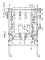
- Fig. 2 is a fragmentary top plan view of the stacker shown in Fig. 1 illustrating the infeed section thereof in accordance with the present preferred embodiment of the invention.
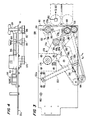
- Fig. 3 is an elevational view of the infeed section of Fig. 2.
- Fig. 4 is a fragmentary top plan view illustrating a portion of the infeed section of Figs. 2 and 3.
- Figs. 5 and 6 both partially sectionalized, show views of the upper and lower drive rollers, respectively, of the infeed section of Figs. 2 and 3.
- Fig. 7 is a fragmentary schematic view in elevation of the infeed section of Fig. 2 illustrating the downstream roller assembly.
- Stacker 30 of the present invention shown in Fig. 1 is comprised of infeed section 100, stacking section 200, turntable section 300 and control section 400.
- Infeed section 100 is coupled to a press conveyor, by means not shown but which are conventional and have been omitted herein for purposes of simplicity, said coupling means aligning and coupling infeed section 100 with delivery conveyor 32 which delivers signatures 34 in an overlapping stream with folded edges 34 forward (see Fig. 2).
- the stream of overlapping signatures 34 which may be delivered to the stacker 30 at rates of as many as 80,000 per hour or more, is fed between upper and lower conveyor belts 36 and 38 respectively only a portion of which have been shown herein for purposes of simplicity, the downstream ends of said conveyor belts 36 and 38 being entrained about rollers 40 and 42 arranged adjacent to the inlet end of infeed section 100.
- FIGs. 2 to 5 which show the infeed section 100 in greater detail, said section is comprised of side plates 101, 103 which are maintained in spaced parallel fashion by spacers 102 and 104, among other components.
- Left-hand ends 101a, 103a of plates 101, 103 are provided with openings for securing plates 101, 103 to the stacker supporting frame by suitable fastening means.
- inlet end of infeed section 100 has a throat portion T for receiving signatures from the adjacent conveyor, which throat portion, as well as the signature feeding portion, is defined by upper and lower belt assemblies 106 and 108.
- upper belt assembly 10b is comprised of belts 110, 112 and 114 which are entrained about upstream roller 116, downstream rollers 110, 120 and 122, and intermediate rollers 124, 126.
- An intermediate roller assembly comprised of roller 124 supports the intermediate portion of belts 112 and 114. Rollers 124 and 126 are mounted upon common shaft 130. Rollers 118, 120 and 122 are mounted upon common shaft 128.
- Lower belt assembly 108 is comprised of roller 131 about which the upstream ends of belts 132, 134 and 136 are entrained. The downstream ends of these belts are entrained about rollers 138, 140 and 142 mounted upon common shaft 144 which is mounted at the free ends of swingably mounted about shaft 150.
- a pair of air cylinders 152, 152 are pivotally mounted at their upper ends 152a to a bearing supporting bracket assembly 154, 156. The free end of each reciprocating piston rod 152b is coupled to one of the swingable arm assemblies 148 by pin 158. Referring to Fig.
- suitable ports provide for the ingress and egress of gas under pressure for moving piston rods 152b, 152b generally upwardly to retain the lower belt assembly 108 in the operative position shown in Fig. 3 and alternatively for moving the piston rods 152b, 152b generally downwardly to swing arm assemblies 146, 148 counterclockwise about pivot 150 as shown by arrow A1, to move the free ends of arm assemblies 146, 148 and thereby move rollers 138, 140 and 142 away from the cooperating rollers 118, 120 and 122.
- the swingable assemblies 146, 148 and air cylinders 152, 152 serve as a drop gate which, under certain circumstances, serve to prevent the flow of signatures to the stacking section when the drop gate assembly is open, enabling the signatures to fall harmlessly upon the floor and thereby prevent the signatures from aggravating a jam condition in the stacker 10.
- Upper drive roller 116 shown in Figs. 3 and 5 is a substantially hollow member and is crowned at 116a and 116b for receiving and supporting belts 110 and 114 and for maintaining these belts centered upon crown regions 116a and 116b (see Fig. 5).
- a centrally located crown 116c receives and positions belt 112 and maintains it centered about center line 116d.
- belts 110 and 114 are substantially wider than belt 112.
- Fig. 6 shows lower drive roller 160 which is crowned at 160a and 160b to receive and support belts 132 and 136 and which maintain these belts centered on the aforesaid crowns.
- a centrally located crown 160 having a significantly greater radius of curvature receives and supports belt 134 and maintains it centered about center line 160d.
- Belt 134 is significantly wider than belts 132 and 136. It is further to be noted that belts 132, 136 and 112 are all substantially the same width and are significantly narrower than belts 110, 114 and 134 which are all substantially the same width and hence significantly wider than belts 112, 132 and 136.
- Upper belts 110 and 114 have their lower ends entrained about rollers 118 and 122 which are crowned in the same manner as roller portions 116a and 116b of upper drive roller 116.
- the downstream end of upper belt 112 is entrained about roller 120 which is crowned in a manner similar to the crown 116c provided at the central portion of roller 116 shown in detail in Fig. 5.
- Upper rollers 118 and 122 have substantially the same diameter and axial length. These rollers are significantly longer and smaller in diameter than roller 120. Conversely, lower driven rollers 138 and 142, which are of the same diameter and axial length, are significantly greater in diameter and shorter in axial length than lower driven roller 140.
- rollers 118 through 122 and 138 through 142 can best be appreciated from a consideration of the simplified elevational view of these rollers shown in Fig. 7.
- the axial length of rollers 118 and 122 are each significantly greater than the axial length of rollers 138 and 142.
- the diameters of rollers 118 and 122 are significantly smaller than the diameters of rollers 138 and 142.
- Roller 120 has a shorter axial length and a greater diameter than roller 140.
- the rollers 120, 138, 142 at the downstream end of the infeed section 100 are preferably rounded at their ends.
- the diameters and axial length of the aforementioned downstream driven rollers serves to urge the signatures into a substantially V-shaped contour as shown by signatures' in Fig. 7.
- the unique aspect of the present invention resides in the fact that the conventional technique for obtaining Veeing of the signatures requires the provision of split shafts for both the upper and lower driven roller assemblies and to mount rollers of substantially uniform diameter and axial length upon the Veed shaft portions. In addition, in the conventional arrangement, the rollers do not engage the signatures at the imaginary center line of the signatures.
- the unique arrangement of the present invention which employs straight, parallel shafts 128 and 144 and rollers of varying diameter and axial length, provides for the Veeing of signatures as well as providing an arrangemeant in which rollers 120 and 140 and hence the belts 112 and 134 entrained therearound make rolling engagement with each signature along the center line of the Veed configuration, thus assuring better alignment and feeding of the signatures.
- a signature counter 164 which may be any conventional signature counter employed to count passing signatures by developing a pulse as the nose of each signature passes the signature counter.
- the signature counter 164 may, for example, be a mechanical device having a gear-like member which is advanced by a fraction of a revolution each time it is engaged by the forward folded edge of a signature which rotates the gear-like member through said fraction of a revolution to provide a count pulse.
- the signature counter may utilize other techniques such as optical or photoelectric techniques to generate a pulse as the forward folded edge of each signature passes the signature counter a signature detector and counter of the acoustic type as described in copending application filed in the U.S.
- the output pulses of the signature counter are utilized in the signature counting and stacking operations, typically in the following manner: Knowing the geometry of the stacker apparatus 30 and given the velocity of the signatures at any given time, the precise moment when the leading edge of a signature reaches the intercept position can be accurately calculated.
- Each of the aforesaid pulses generated by the signature counter are applied to the microprocessor-base controller 400 (Fig. 1) to determine when the signature, after moving from the position where it is counted by signature counter 164, reaches a predetermined position, such as, for example, the intercept position, which will be described in greater detail hereinbelow.
- the infeed section 100 further comprises a motor and gear reducer 172 for driving pulley 174 mounted upon the output shaft 172a of gear reducer 172.
- a double sided pulley belt 176 represented by a chain line, is entrained about timing pulleys in such a way that run 176a extends between pulley 174 and pulley 178, run 176b extends between pulleys 178 and 180; run 176c extends between pulley 180 and pulley 182; run 176d extends between pulley 182 and idler pulley 184 and run 176e extends between idler pulley 184 and pulley 174.
- Pulleys 180 and 182 are respectively coupled to shafts 186 and 188 for respectively rotating the upper and lower drive rollers 116 and 160.
- Pulley 184 may be adjustably positioned along slots 101b, 103b to adjust the tension on belt 176.
- Aforementioned throat region T which serves to guide signatures delivered from the press conveyor, has a substantially V-shaped throat portion, which is defined by the right-hand end of the lower run of belts 110, 112 and 114 which are diagonally aligned as shown in Fig. 3, as well as the right-hand portion of the upper run of belts 132, 134 and 136 and specifically the portion of the upper run of these belts extending between roller 160 and an intermediate roller 192 mounted for freewheeling rotation upon shaft 194 which in turn is supported by the swingable arms 146 and 148 (see Figs. 2 and 3).
- the signatures are ultimately firmly gripped between the upper and lower belt runs as their forward folded edges pass over the portion of the belts 132 and 134 and 136 extending around roller 192.
- the belts are moved at a linear speed which corresponds to the linear speed of the belts 36, 38 employed deliver the signatures to the infeed section 100 by the press conveyor 22 (Fig. 1).
- a tachometer generator 195 is coupled, for example, to the shaft of the press conveyor upper driving roller 20 for developing a voltage level proportional to speed generated by tachometer generator 195, said pulses representing the linear speed of the press conveyor belts and hence the signatures passing therethrough.
- These voltage levels are coupled through an electrical interface 197 (see Fig. 2) forming part of the stacker 30 electronics which is coupled to motor 172 to control motor 172 and its gear reducer unit which determines the rotational speed of the roller shafts 186 and 188 and hence the rotating speed of the upper and lower drive rollers 116 and 160.
- a tachometer 196 is coupled to shaft 186 and generates pulses as shaft 186 rotates, said pulses representing the linear speed of the belts 110, 112 and 114.
- the pulses from tachometer 196 are utilized by the stacker controller in the tracking of signatures, as will be more fully described hereinbelow.
Landscapes
- Engineering & Computer Science (AREA)
- Mechanical Engineering (AREA)
- Delivering By Means Of Belts And Rollers (AREA)
- Pile Receivers (AREA)
- Feeding Of Articles By Means Other Than Belts Or Rollers (AREA)
- Separation, Sorting, Adjustment, Or Bending Of Sheets To Be Conveyed (AREA)
- Forming Counted Batches (AREA)
- Conveying Record Carriers (AREA)
Claims (20)
- Verfahren zum Transportieren von Bogen längs eines Weges zwischen Förderern (106, 108) von einem stromaufwärtigen Ort zu einem stromabwärtigen Ort und zum Formen der Bogen (S) in eine V-förmige Konfiguration,
gekennzeichnet durch die Schritte:
Zuführen der Bogen (S) zwischen einer ersten Vielzahl von endlosen Schleifengliedern (110, 112, 114) auf dem ersten Förderer (106) und einer zweiten Vielzahl von endlosen Schleifengliedern (132, 134, 136) auf dem zweiten Förderer (108);
Antreiben jeder der ersten und zweiten Vielzahl von endlosen Schleifengliedern (110, 112, 114; 132, 134, 136) im wesentlichen längs des Weges mit im wesentlichen identischen Geschwindigkeiten;
Ausrichten der ersten Vielzahl von endlosen Schleifengliedern (110, 112, 114) in einer V-förmigen Konfiguration mit einer jeweiligen ersten Vielzahl von Rollen (118, 120, 122), die koaxial längs einer ersten Achse quer zum Weg gelagert sind und unterschiedliche Durchmesser haben, die eine V-Form definieren;
Ausrichten der zweiten Vielzahl von endlosen Schleifengliedern (132, 134, 136) in einer V-förmigen Konfiguration gegenüberliegend zu der ersten Vielzahl von endlosen Schleifengliedern (110, 112, 114) mit einer jeweiligen zweiten Vielzahl von Rollen (138, 140, 142), die Koaxial längs einer zweiten Achse quer zum weg und gegenüberliegend zur ersten Vielzahl von Rollen (118, 120, 122) gelagert sind und unterschiedliche Durchmesser komplementär zu den jeweiligen Durchmessern der ersten Vielzahl von Rollen haben;
Transportieren der Bogen (S) längs des Weges durch Beaufschlagen der Bogen (S) mit den endlosen Schleifengliedern (110, 112, 114; 132, 134, 136) und Formen der Bogen (S) in eine V-förmige Konfiguration mit den endlosen Schleifengliedern (110, 112, 114; 132, 134, 136), und
Ausgeben der Bogen (S) in einer V-förmigen Konfiguration von den Förderern (106, 108) an dem stromabwärtigen Ort. - Verfahren nach Anspruch 1, wobei die erste Vielzahl (110, 112, 114) und die zweite Vielzahl (132, 134, 136) der endlosen Schleifenglieder eine im wesentlichen flache Konfiguration haben.
- Verfahren nach Anspruch 1 oder 2, wobei der Formungsschritt ein Zusammenpressen der Bogen (S) zwischen den Förderern (106, 108) und ein allmähliches Formen der Bogen (S) in eine V-Konfiguration längs des Weges von dem stromaufwärtigen Ort zu dem stromabwärtigen Ort umfaßt.
- Vorrichtung zum Transportieren von Bogen längs eines Weges zwischen zwei Förderern (106, 108) von einem stromaufwärtigen Ort zu einem stromabwärtigen Ort und zum Formen der Bogen (S) in eine V-förmige Konfiguration,
gekennzeichnet durch:
einen ersten Förderer (106), der eine Vielzahl von Rollen (118, 120, 122), die koaxial längs einer ersten Achse quer zu dem Weg gelagert sind, wobei die erste Vielzahl von Rollen (118, 120, 122) Umfangsflächen und unterschiedliche Durchmesser haben, die eine V-Form definieren, und eine erste Vielzahl von endlosen Schleifengliedern (110, 112, 114) hat, die zum Verlaufen längs des Weges gelagert sind und jeweils über die Umfangsflächen der ersten Vielzahl von Rollen (118, 120, 122) zum Transportieren der Bogen (S) längs des Weges laufen;
einen zweiten Förderer (108), der eine zweite Vielzahl von Rollen (138, 140, 142), die koaxial längs einer zweiten Achse quer zu dem Weg gelagert sind, wobei die zweite Vielzahl von Rollen (138, 140, 142) jeweils Umfangsflächen gegenüberliegend zu den jeweiligen Umfangsflächen der ersten Vielzahl von Rollen (118, 120, 122) haben, wobei die zweite Vielzahl von Rollen (138, 140, 142) Durchmesser komplementär zu der ersten Vielzahl von Rollen (118, 120, 122) haben, um ebenfalls die V-Form zu definieren, und eine zweite Vielzahl von endlosen Schleifengliedern (132, 134, 136) hat, die der ersten Vielzahl von endlosen Schleifengliedern (110, 112, 114) gegenüberliegen und zum Verlaufen längs des Weges gelagert sind und jeweils über die Umfangsflächen der zweiten Vielzahl von Rollen (138, 140, 142) zum Transportieren der Bogen (S) längs des Weges laufen, und
eine Antriebseinrichtung (172) zum Antreiben der ersten und zweiten endlosen Schleifenglieder (110, 112, 114; 132, 134, 136) mit im wesentlichen identischen Geschwindigkeiten. - Vorrichtung nach Anspruch 4, wobei die erste Vielzahl (110, 112, 114) und die zweite Vielzahl (132, 134, 136) der endlosen Schleifenglieder eine im wesentlichen flache Konfiguration haben.
- Vorrichtung nach Anspruch 4 oder 5, die erste und zweite Wellen (128, 144) umfaßt, wobei die erste Vielzahl von Rollen (118, 120, 122) alle auf der ersten Welle (128) gelagert ist und die zweite Vielzahl von Rollen (138, 140, 142) alle auf der zweiten Welle (144) gelagert ist.
- Vorrichtung nach Anspruch 4, wobei die Rollen (118, 120, 122; 138, 140, 142) scheitelförmig geformt sind.
- Vorrichtung nach Anspruch 4, die eine Zusammendrückeinrichtung (152) zum Zwingen der ersten und zweiten Förderer (106, 108) aufeinanderzu zum Zusammenpressen der Bogen (S) zwischen den ersten und zweiten Förderern (106, 108) umfaßt.
- Vorrichtung nach Anspruch 4, wobei die Antriebseinrichtung dritte und vierte Rollen (116, 160) umfaßt, um die die ersten und zweiten endlosen Schleifenglieder (110, 112, 114; 132, 134, 136) jeweils geschlungen sind.
- Vorrichtung nach Anspruch 9, wobei die erste und zweite Vielzahl von Rollen (118, 120, 122; 138, 140, 142) an dem stromabwärtigen Ort gelagert sind, und die dritten und vierten Rollen (116, 160) an dem stromaufwärtigen Ort gelagert sind.
- Vorrichtung nach Anspruch 9, wobei die dritte Rolle (116) eine Vielzahl von Antriebsteilen (116a, 116b, 116c) umfaßt, die Umfangsflächenteile haben, die im wesentlichen identisch im Durchmesser zueinander sind, und um die die erste Vielzahl von endlosen Schleifengliedern (110, 112, 114) geschlungen sind, und wobei die vierte Rolle (160) eine Vielzahl von Antriebsteilen (160a, 160b, 160c) umfaßt, die Umfangsteile haben, die im wesentlichen identisch im Durchmesser zueinander sind und um die die zweite Vielzahl von endlosen Schleifengliedern (132, 134, 136) geschlungen sind.
- Vorrichtung nach Anspruch 11, wobei die Antriebsteile (116a, 116b, 116c; 160a, 160b, 160c) der dritten und vierten Rolle (116, 160) scheitelförmig geformt sind.
- Vorrichtung nach Anspruch 4, wobei die erste und zweite Vielzahl von Rollen (118, 120, 122; 138, 140, 142) gegenüberliegende Paare von Rollen (118, 138; 120, 140; 122, 142) umfassen, wobei eine Rolle des Paares eine unterschiedliche axiale Länge zu der der anderen Rolle des Paares hat.
- Vorrichtung nach Anspruch 8, wobei die Zusammendrückungseinrichtung (152) eine Zwischenrollenanordnung (124, 126) umfaßt, die an einem (106) der ersten und zweiten Förderer (106, 108) zwischen dem stromaufwärtigen und dem stromabwärtigen Ort gelagert ist.
- Vorrichtung nach Anspruch 4, wobei eine (118, 120, 122) der ersten und zweiten Vielzahlen von Rollen (118, 120, 122; 138, 140, 142) eine zentrische Rolle (120) hat, die eine axiale Länge und einen maximalen Durchmesser größer als die axiale Länge hat.
- Vorrichtung nach Anspruch 4, wobei die Rollen der ersten Vielzahl von Rollen (118, 120, 122) sich bezüglich zueinander drehen und die Rollen der zweiten Vielzahl von Rollen (138, 140, 142) sich bezüglich zueinander drehen.
- Vorrichtung nach Anspruch 4, wobei die erste und zweite Vielzahl von Rollen (118, 120, 122; 138, 140, 142) gegenüberliegende Paare von Rollen (118, 138; 120, 140; 122, 142) umfassen, wobei eine Rolle des Paares einen größeren Durchmesser und eine kleinere axiale Länge als die andere Rolle des Paares hat.
- Vorrichtung nach Anspruch 17, wobei der Durchmesser der einen Rolle (138) des Paares größer als ihre axiale Länge ist und der Durchmesser der anderen Rolle (118) geringer als ihre axiale Länge ist.
- Vorrichtung nach Anspruch 4, wobei die erste Vielzahl von Rollen (118, 120, 122) eine zentrische Rolle (120) und zwei Endrollen (118, 122) umfaßt, wobei die zentrische Rolle (120) der ersten Vielzahl von Rollen (118, 120, 122) einen größeren Durchmesser und eine kleinere axiale Länge als die zwei Endrollen (118, 122) der ersten Vielzahl von Rollen hat, und die zweite Vielzahl von Rollen (138, 140, 142) eine zentrische Rolle (140) und zwei Endrollen (138, 142) umfaßt, wobei die zentrische Rolle (140) der zweiten Vielzahl von Rollen (138, 140, 142) einen kleineren Durchmesser und eine größere axiale Länge als die zwei Endrollen (138, 142) der zweiten Vielzahl von Rollen hat.
- Vorrichtung nach Anspruch 4, wobei die erste und zweite Vielzahl von endlosen Schleifengliedern (110, 112, 114; 132, 134, 136) jeweils an dem stromabwärtigen Ort von der ersten und zweiten Vielzahl von Rollen (118, 120, 122; 138, 140, 142) gehalten sind, um eine V-Form an dem stromabwärtigen Ort zu definieren, und die erste und zweite Vielzahl von endlosen Schleifengliedern (110, 112, 114; 132, 134, 136) an dem stromaufwärtigen Ort gehaltert sind, um eine flache Form an dem stromaufwärtigen Ort zu definieren, so daß die endlosen Schleifenglieder (110, 112, 114; 132, 134, 136) allmählich flache Bogen (S) in eine V-förmige Konfiguration formen, während die Bogen (S) von dem stromaufwärtigen Ort zu dem stromabwärtigen Ort transportiert werden.
Priority Applications (1)
| Application Number | Priority Date | Filing Date | Title |
|---|---|---|---|
| EP91106061A EP0444716B1 (de) | 1986-06-20 | 1987-06-10 | Vorrichtung und Verfahren zum Stapeln von Blättern |
Applications Claiming Priority (2)
| Application Number | Priority Date | Filing Date | Title |
|---|---|---|---|
| US876490 | 1986-06-20 | ||
| US06/876,490 US5024569A (en) | 1986-06-20 | 1986-06-20 | Stacking method and apparatus |
Related Child Applications (1)
| Application Number | Title | Priority Date | Filing Date |
|---|---|---|---|
| EP91106061.4 Division-Into | 1991-04-16 |
Publications (2)
| Publication Number | Publication Date |
|---|---|
| EP0249874A1 EP0249874A1 (de) | 1987-12-23 |
| EP0249874B1 true EP0249874B1 (de) | 1991-11-13 |
Family
ID=25367837
Family Applications (2)
| Application Number | Title | Priority Date | Filing Date |
|---|---|---|---|
| EP87108399A Expired EP0249874B1 (de) | 1986-06-20 | 1987-06-10 | Verfahren und Einrichtung zum Transport von Bogen zwischen zwei Förderbändern |
| EP91106061A Expired - Lifetime EP0444716B1 (de) | 1986-06-20 | 1987-06-10 | Vorrichtung und Verfahren zum Stapeln von Blättern |
Family Applications After (1)
| Application Number | Title | Priority Date | Filing Date |
|---|---|---|---|
| EP91106061A Expired - Lifetime EP0444716B1 (de) | 1986-06-20 | 1987-06-10 | Vorrichtung und Verfahren zum Stapeln von Blättern |
Country Status (6)
| Country | Link |
|---|---|
| US (1) | US5024569A (de) |
| EP (2) | EP0249874B1 (de) |
| JP (1) | JPS6347263A (de) |
| AU (1) | AU641234B2 (de) |
| CA (1) | CA1306474C (de) |
| DE (2) | DE3751498D1 (de) |
Families Citing this family (15)
| Publication number | Priority date | Publication date | Assignee | Title |
|---|---|---|---|---|
| US5338149A (en) * | 1984-04-02 | 1994-08-16 | Idab Incorporated | Signature stacker |
| US5029842A (en) * | 1988-12-23 | 1991-07-09 | Harris Graphics Corporation | Signature handling apparatus |
| JPH02197428A (ja) * | 1989-01-24 | 1990-08-06 | Kojima Press Co Ltd | 車両の暴走防止装置 |
| US5114306A (en) * | 1989-09-19 | 1992-05-19 | Quipp, Incorporated | Dual drive stacker and method for operating same |
| US5107733A (en) * | 1991-06-14 | 1992-04-28 | Heidelberg Harris Gmbh | Apparatus for cutting and transporting a paper web in a folding apparatus of a printing press |
| US6647849B2 (en) | 1998-07-30 | 2003-11-18 | Heidelberger Druckmaschinen | Device for varying a cylinder's effective diameter |
| US6518997B1 (en) * | 1998-08-05 | 2003-02-11 | National Semiconductor Corporation | Grid array inspection system and method |
| US6394445B1 (en) * | 1998-12-30 | 2002-05-28 | Quad/Tech, Inc. | Apparatus for slowing down and guiding a signature and method for doing the same |
| DE10317948A1 (de) * | 2003-04-17 | 2004-10-28 | Gämmerler AG | Handhabungssystem |
| DE102006018768B4 (de) * | 2006-04-20 | 2008-02-07 | Kugler-Womako Gmbh | Vorrichtung zum Transport bogenförmiger flacher Gegenstände |
| EP2138439B1 (de) * | 2008-05-23 | 2015-05-20 | Ferag AG | Vorrichtung zum Stapeln von flächigen Produkten, insbesondere Druckereiprodukten |
| KR101310131B1 (ko) * | 2009-06-02 | 2013-09-23 | 무라다기카이가부시끼가이샤 | 무한 구동 매체를 구비한 반송 시스템과 여기에서의 물품 전달 방법 |
| JP4889805B2 (ja) * | 2010-08-06 | 2012-03-07 | シャープ株式会社 | シート搬送装置及びそれを備えた画像形成装置 |
| CH705846A1 (de) * | 2011-12-07 | 2013-06-14 | Ferag Ag | Einrichtung und Verfahren zum Zusammenstellen von flächigen Produkten, insbesondere von Druckereiprodukten. |
| WO2017187529A1 (ja) * | 2016-04-26 | 2017-11-02 | 富士通フロンテック株式会社 | 紙葉類取扱装置及び紙葉類取扱方法 |
Family Cites Families (32)
| Publication number | Priority date | Publication date | Assignee | Title |
|---|---|---|---|---|
| US595239A (en) * | 1897-12-07 | Dress-chart | ||
| US1117244A (en) * | 1913-05-31 | 1914-11-17 | Carey A Cheshire | Stacking-machine. |
| US3115090A (en) * | 1959-11-05 | 1963-12-24 | Elander Douglas | Packing machine |
| US3186565A (en) * | 1962-01-15 | 1965-06-01 | Johns Manville | Automatic shingle stacker |
| DE1253170B (de) * | 1963-10-01 | 1967-10-26 | Telefunken Patent | Stapeleinrichtung fuer flaches Foerdergut, wie insbesondere Postsendungen |
| US3292505A (en) * | 1964-02-21 | 1966-12-20 | Raymond L Wiseman | Art of intercepting spaced groups of flat overlapping books |
| SE311664B (de) * | 1965-12-23 | 1969-06-23 | Bonnierfoeretagen Ab | |
| US3326353A (en) * | 1966-02-15 | 1967-06-20 | Dev And Control Ltd Sa | Conveyor system with jam release |
| US3429239A (en) * | 1966-02-15 | 1969-02-25 | Dev & Control Ltd Sa | Stacker for newspapers and the like |
| US3379320A (en) * | 1966-09-22 | 1968-04-23 | Sheridan Loach Ltd | Compensating stacker |
| US3418895A (en) * | 1967-06-20 | 1968-12-31 | Charles G. Palmer | Control system for article stackers |
| US3479932A (en) * | 1968-03-14 | 1969-11-25 | Ind Dev Ab | Bucket drive |
| US3526170A (en) * | 1968-03-29 | 1970-09-01 | Sta Hi Corp | Automatic stacking device for publication conveyor |
| US3548995A (en) * | 1968-06-13 | 1970-12-22 | Sta Hi Corp | Controlled variable speed stacking device for publication conveyor |
| US3568815A (en) * | 1968-07-26 | 1971-03-09 | Sta Hi Corp | Outfeed conveyor mechanism of a conveyor system for conveying units such as stacks of publications and the like |
| CH488616A (de) * | 1969-02-28 | 1970-04-15 | Graphicart Int | Maschine zum automatischen Stapeln von in vorwählbarer Anzahl abgezählten Zeitungen |
| US3596779A (en) * | 1969-04-14 | 1971-08-03 | Davis Machine Corp | Bag collating and stacking apparatus |
| US3611887A (en) * | 1969-08-21 | 1971-10-12 | Hamada Printing Press | Apparatus for feeding and stacking folded printed articles in bundles |
| US3752043A (en) * | 1970-05-29 | 1973-08-14 | Licentia Gmbh | Stack forming apparatus |
| US3908985A (en) * | 1971-11-11 | 1975-09-30 | Raymond L Wiseman | Method and means for stacking articles |
| SE372733B (de) * | 1972-03-10 | 1975-01-13 | Europ Copyright Service Ab | |
| JPS4962212A (de) * | 1972-10-18 | 1974-06-17 | ||
| CH567996A5 (en) * | 1973-06-22 | 1975-10-15 | Ferag Ag | Equipment for stacking printed products - has stacking shaft with pushing out devices along two sides |
| SE387612B (sv) * | 1975-04-16 | 1976-09-13 | Wamac Ab | Anordning med en uppsamlingskorg for uppsamling av trycksaker i form av en stapel och avlemning av stapeln |
| US4037525A (en) * | 1975-07-30 | 1977-07-26 | Eds, Inc. | Signature stacker employing swingable intercept means driven in a non-linear fashion |
| US4125253A (en) * | 1975-10-22 | 1978-11-14 | Gruner & Jahr Ag & Co. | Method of providing a stack of predetermined length and apparatus for performing said method |
| US4103785A (en) * | 1976-08-18 | 1978-08-01 | Wiseman Raymond L | Apparatus for rotating and discharging articles |
| US4068567A (en) * | 1977-01-31 | 1978-01-17 | Cutler-Hammer, Inc. | Combined ejector-gate means for rotatable table of an article counter-stacker |
| US4148393A (en) * | 1977-05-27 | 1979-04-10 | Wiseman Raymond L | Sensing device and method |
| US4162733A (en) * | 1977-06-21 | 1979-07-31 | Wiseman Raymond L | Article stacking apparatus |
| IT1135338B (it) * | 1981-02-06 | 1986-08-20 | Omg Pessina Perobelli | Tavola girevole perfezionata per impilatori per legatorie e simili |
| US4678387A (en) * | 1985-03-01 | 1987-07-07 | Quipp Incorporated | Signature stacker |
-
1986
- 1986-06-20 US US06/876,490 patent/US5024569A/en not_active Expired - Fee Related
-
1987
- 1987-05-27 CA CA000538072A patent/CA1306474C/en not_active Expired - Fee Related
- 1987-06-10 EP EP87108399A patent/EP0249874B1/de not_active Expired
- 1987-06-10 EP EP91106061A patent/EP0444716B1/de not_active Expired - Lifetime
- 1987-06-10 DE DE3751498T patent/DE3751498D1/de not_active Expired - Lifetime
- 1987-06-10 DE DE8787108399T patent/DE3774491D1/de not_active Expired - Fee Related
- 1987-06-19 JP JP62151528A patent/JPS6347263A/ja active Pending
-
1991
- 1991-04-19 AU AU75112/91A patent/AU641234B2/en not_active Ceased
Also Published As
| Publication number | Publication date |
|---|---|
| EP0444716B1 (de) | 1995-08-30 |
| DE3774491D1 (de) | 1991-12-19 |
| EP0249874A1 (de) | 1987-12-23 |
| AU7511291A (en) | 1991-07-18 |
| CA1306474C (en) | 1992-08-18 |
| AU641234B2 (en) | 1993-09-16 |
| EP0444716A1 (de) | 1991-09-04 |
| DE3751498D1 (de) | 1995-10-05 |
| JPS6347263A (ja) | 1988-02-29 |
| AU7337887A (en) | 1987-12-24 |
| US5024569A (en) | 1991-06-18 |
| AU604703B2 (en) | 1991-01-03 |
Similar Documents
| Publication | Publication Date | Title |
|---|---|---|
| SU1762737A3 (ru) | Устройство дл изготовлени рогаликов из скатанного теста | |
| US4330116A (en) | Bundling mechanism for signatures | |
| CA2031116C (en) | Printed paper folding machine | |
| US5244198A (en) | Gate forming member for sheet feeding apparatus | |
| EP0487592A1 (de) | Blattzuführeinrichtung. | |
| EP1142465A2 (de) | Verfahren und Vorrichtung zum Regulieren der Intervalle von Setzlingen | |
| CN1165107A (zh) | 用于分离堆积的扁平件的装置 | |
| CA2099267A1 (en) | Paper sheet feeding apparatus | |
| JPH07107896A (ja) | クロワッサン生地の折り曲げ装置 | |
| JPS59102754A (ja) | 分岐装置 | |
| CA1306474C (en) | Stacking method and apparatus | |
| CA2739009C (en) | Apparatus and method for transporting flexible, planar products | |
| JP4593818B2 (ja) | 折丁減速装置 | |
| EP0609686B1 (de) | Maschine zum Stapeln mit Schnellmontageeinrichtung | |
| US5209466A (en) | Apparatus and method for forming signature into a V-configuration | |
| JPH09188437A (ja) | 循環する連行部材によって規則的な間隔をおいて搬送装置の鞍形載置部に跨がって搬送される印刷製品を取り出すための装置 | |
| KR100199354B1 (ko) | 연속적인 이동웹을 정지위치의 스테이션에서 처리하기위한이송기구 | |
| EP0302169B1 (de) | Hochgeschwindigkeitsablegevorrichtung für gedrückte Gegenstände | |
| CA2270626A1 (en) | Method and apparatus for separating 2-up sheets | |
| US5783218A (en) | Mechanism for powdering bread dough being stretched | |
| JPS6348778B2 (de) | ||
| US5443256A (en) | Process and device for the formation of a scale-like stream of folded printed copies | |
| JP2935218B1 (ja) | 折り機の排出装置における折り丁排出ピッチ揃え装置 | |
| JP3132307B2 (ja) | シート状部材の区分け装置 | |
| JP3758848B2 (ja) | 枚葉印刷機の給紙装置 |
Legal Events
| Date | Code | Title | Description |
|---|---|---|---|
| PUAI | Public reference made under article 153(3) epc to a published international application that has entered the european phase |
Free format text: ORIGINAL CODE: 0009012 |
|
| AK | Designated contracting states |
Kind code of ref document: A1 Designated state(s): CH DE FR GB IT LI NL SE |
|
| 17P | Request for examination filed |
Effective date: 19880506 |
|
| RAP3 | Party data changed (applicant data changed or rights of an application transferred) |
Owner name: EDS TECHNOLOGIES, INC. |
|
| 17Q | First examination report despatched |
Effective date: 19890825 |
|
| GRAA | (expected) grant |
Free format text: ORIGINAL CODE: 0009210 |
|
| AK | Designated contracting states |
Kind code of ref document: B1 Designated state(s): CH DE FR GB IT LI NL SE |
|
| XX | Miscellaneous (additional remarks) |
Free format text: TEILANMELDUNG 91106061.4 EINGEREICHT AM 10/06/87. |
|
| REF | Corresponds to: |
Ref document number: 3774491 Country of ref document: DE Date of ref document: 19911219 |
|
| ITF | It: translation for a ep patent filed | ||
| ET | Fr: translation filed | ||
| PLBE | No opposition filed within time limit |
Free format text: ORIGINAL CODE: 0009261 |
|
| STAA | Information on the status of an ep patent application or granted ep patent |
Free format text: STATUS: NO OPPOSITION FILED WITHIN TIME LIMIT |
|
| 26N | No opposition filed | ||
| EAL | Se: european patent in force in sweden |
Ref document number: 87108399.4 |
|
| PGFP | Annual fee paid to national office [announced via postgrant information from national office to epo] |
Ref country code: SE Payment date: 19950511 Year of fee payment: 9 Ref country code: CH Payment date: 19950511 Year of fee payment: 9 |
|
| PGFP | Annual fee paid to national office [announced via postgrant information from national office to epo] |
Ref country code: NL Payment date: 19950522 Year of fee payment: 9 |
|
| PGFP | Annual fee paid to national office [announced via postgrant information from national office to epo] |
Ref country code: FR Payment date: 19950526 Year of fee payment: 9 Ref country code: DE Payment date: 19950526 Year of fee payment: 9 |
|
| PGFP | Annual fee paid to national office [announced via postgrant information from national office to epo] |
Ref country code: GB Payment date: 19950530 Year of fee payment: 9 |
|
| PG25 | Lapsed in a contracting state [announced via postgrant information from national office to epo] |
Ref country code: GB Effective date: 19960610 |
|
| PG25 | Lapsed in a contracting state [announced via postgrant information from national office to epo] |
Ref country code: SE Effective date: 19960611 |
|
| PG25 | Lapsed in a contracting state [announced via postgrant information from national office to epo] |
Ref country code: LI Effective date: 19960630 Ref country code: CH Effective date: 19960630 |
|
| PG25 | Lapsed in a contracting state [announced via postgrant information from national office to epo] |
Ref country code: NL Effective date: 19970101 |
|
| GBPC | Gb: european patent ceased through non-payment of renewal fee |
Effective date: 19960610 |
|
| REG | Reference to a national code |
Ref country code: CH Ref legal event code: PL |
|
| PG25 | Lapsed in a contracting state [announced via postgrant information from national office to epo] |
Ref country code: FR Effective date: 19970228 |
|
| PG25 | Lapsed in a contracting state [announced via postgrant information from national office to epo] |
Ref country code: DE Effective date: 19970301 |
|
| EUG | Se: european patent has lapsed |
Ref document number: 87108399.4 |
|
| NLV4 | Nl: lapsed or anulled due to non-payment of the annual fee |
Effective date: 19970101 |
|
| REG | Reference to a national code |
Ref country code: FR Ref legal event code: ST |
|
| PG25 | Lapsed in a contracting state [announced via postgrant information from national office to epo] |
Ref country code: IT Free format text: LAPSE BECAUSE OF NON-PAYMENT OF DUE FEES;WARNING: LAPSES OF ITALIAN PATENTS WITH EFFECTIVE DATE BEFORE 2007 MAY HAVE OCCURRED AT ANY TIME BEFORE 2007. THE CORRECT EFFECTIVE DATE MAY BE DIFFERENT FROM THE ONE RECORDED. Effective date: 20050610 |