EP0249838A1 - Equipement pour commander une installation magnétique pour l'autoprotection - Google Patents
Equipement pour commander une installation magnétique pour l'autoprotection Download PDFInfo
- Publication number
- EP0249838A1 EP0249838A1 EP87108207A EP87108207A EP0249838A1 EP 0249838 A1 EP0249838 A1 EP 0249838A1 EP 87108207 A EP87108207 A EP 87108207A EP 87108207 A EP87108207 A EP 87108207A EP 0249838 A1 EP0249838 A1 EP 0249838A1
- Authority
- EP
- European Patent Office
- Prior art keywords
- data
- field
- compensation
- vehicle
- magnetic
- Prior art date
- Legal status (The legal status is an assumption and is not a legal conclusion. Google has not performed a legal analysis and makes no representation as to the accuracy of the status listed.)
- Granted
Links
Images


Classifications
-
- B—PERFORMING OPERATIONS; TRANSPORTING
- B63—SHIPS OR OTHER WATERBORNE VESSELS; RELATED EQUIPMENT
- B63G—OFFENSIVE OR DEFENSIVE ARRANGEMENTS ON VESSELS; MINE-LAYING; MINE-SWEEPING; SUBMARINES; AIRCRAFT CARRIERS
- B63G9/00—Other offensive or defensive arrangements on vessels against submarines, torpedoes, or mines
- B63G9/06—Other offensive or defensive arrangements on vessels against submarines, torpedoes, or mines for degaussing vessels
Definitions
- the invention relates to a device for controlling a magnetic self-protection (MES) system of a vehicle, which has a large-area, three-axis coil system consisting of current-carrying coils in three orthogonal vehicle axes to compensate for the earth's magnetic field at the vehicle location and the vehicle's movement in the earth's magnetic field (course, roll, Etc.). dependent magnetic field of the vehicle.
- MES magnetic self-protection
- the magnetic self-field contains a so-called permanent component and an induced component, which is due to the permanent magnetization of the vehicle when driving in the earth's field, the size of which varies depending on the course and the position of the vehicle axles to the horizon.
- MES systems are well described in the literature (e.g. Kosack and Wangerin, "Electrical engineering on merchant ships", Springer Verlag 1956, pages 255-257, Fig. 234). They have a large, three-axis coil system consisting of coils through which current flows in three orthogonal axes to compensate for the vehicle's own magnetic field.
- Every vehicle equipped with an MES system first experiences a basic setting of the MES system (initial measurement) based on a so-called magnetic measurement, in which an optimal compensation value is achieved by setting suitable winding currents and suitable coil switching states (ampere-turn numbers).
- the setting changes - apart from long-term changes that require a setting check at certain intervals - while driving.
- the MES system has a regulating device or a controller which adjusts the currents or, by switching windings, the ampere-turn numbers in the individual coils during driving so that the set compensation of the interference field is retained.
- the Gyro MES system is a manual control. Errors in the operation of the controllers are therefore only recognized by manual control. In addition, the eigenfield changes are not recorded in the known system. The known MES system can therefore no longer meet today's requirements with regard to the increased sensitivity of the detonators.
- This known MES system has the following disadvantages: For technical reasons, the probe system, the probe triple, cannot be attached to the vehicle for the cheapest measurement with optimal measuring conditions, but only where it is structurally possible.
- the measurement signal of the probes in the earth's field is the sole control signal for the MES system.
- the system can therefore only be operated by hand, the so-called MES channels being controlled depending on the course. Probe errors are not easily noticed.
- the invention is therefore based on the object of developing the device described at the outset in such a way that it provides substantially better and more reliable magnetic compensation for vehicles than the compensation with conventional MES controls. It is important to achieve an optimal magnetic protection state and to limit the measurement and control of the magnetic protection state from the outside to a minimum in order to increase the operational safety of the system at the same time.
- the invention is intended to be able to be used on highly protected vehicles with an amagnetic and electrically non-conductive outer skin, on highly protected vehicles with a non-magnetic but electrically conductive outer skin and on vehicles with a ferromagnetic outer skin.
- process control with a digital data processor is provided, to which a database is assigned in which - Vehicle-specific data of the first measurement at the measuring location - Location-dependent data on the geomagnetic conditions in the operating area of the vehicle (geomagnetic data) are filed, the on-board sensor for coil data, geomagnetic location, course and vehicle movements are assigned and which controls the number of ampere turns of the compensation coils based on a predetermined sequence control (algorithms) in such a way that optimal compensation is ensured.
- a database is assigned in which - Vehicle-specific data of the first measurement at the measuring location - Location-dependent data on the geomagnetic conditions in the operating area of the vehicle (geomagnetic data) are filed, the on-board sensor for coil data, geomagnetic location, course and vehicle movements are assigned and which controls the number of ampere turns of the compensation coils based on a predetermined sequence control (algorithms) in such a way that optimal compensation is ensured.
- the magnetic opposing fields to compensate for the magnetic effects occurring on or in the vehicle are controlled as a function of the geographical location, the course and the vehicle's own movement.
- the heart of the process-controlled MES system is an intelligent control system with a data processor that uses data storage (database).
- the data storage contains the parameters that are required to achieve optimal control of the MES system. It is the data for the compensation - the location-dependent magnetic effects - The location and course-dependent magnetic effects - The magnetic effects dependent on the vehicle's own movements in the earth's field - The magnetic effects depending on operating conditions.
- the magnetic fields of ferromagnetic objects such as internals and equipment in vehicles as well as their magnetic reaction in different operating states and when moving in the earth's field can be measured precisely. This also applies to the ferromagnetic or non-magnetic outer skin of the vehicle.
- known data transmitters arranged inside the vehicle - without magnetic field probes - it is just as easy to determine the data about the course, location and own movement of the vehicle.
- the data for the control of the MES system are stored in exceptional situations, so that the best possible setting is guaranteed even for a faulty system.
- the data previously obtained via magnetic field probes for the regulation or control of the ampere-turn numbers of the compensation coils are measured using the stored geometric data in conjunction with measured values relating to the geographical location and direct measurement of the vehicle's own movement and the operating states by corresponding sensors inside the vehicle.
- the great advantage of the device according to the invention is that there is no need for a magnetic field probe system which is mechanically very easily damaged, as a result of which operational reliability can be increased considerably.
- the focus is no longer on the measurement and complicated compensation of probe signals, but on the actual regulation / control, with constant digital control. Operating states are taken into account without the detour via the probe reaction. The compensation must therefore be carried out optimally.
- the process-controlled MES system has particularly good uses or advantages on underwater vehicles, since it is always problematic to attach the gastro-field probes to the outer body of the submarines at an exposed point.
- FIG. 1-3 shows the large-scale, three-axis coil system of an MES system of a ship 1 (as an example of a vehicle as a ferromagnetic interference body).
- This coil system consists of coils 2, 3, 4 in the three orthogonal axes XYZ.
- Each coil 2 or 3 or 4 is usually divided into three sub-coils, which are no longer shown.
- One coil section (additional designation P) is used to compensate for a permanent vehicle-dependent interference field component.
- a second coil section (additional designation I) is used to compensate for an interference field component induced by the earth field. Since vortex fields are induced in metallic parts of the system as a result of the ship 1's own movement in the earth's field, it is compensated for with a third coil section (additional designation E).
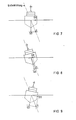
- FIG. 5 shows the ship 1 and the axes of the coordinate system in the same position as in FIG. 4, but now the isolines 12 of the magnetic field are shown in the case of pure longitudinal magnetization of the ship 1.
- a measurement of the vertical field component would have the basic course marked with 13 below the ship 1.
- FIG. 6 shows the ship 1 in a front view and correspondingly the y and z axes of the coordinate system.
- lines 14 of the same field strength are entered schematically with pure transverse magnetization of ship 1. If one measures the vertical component of the magnetic field with such a magnetization in the depth MT, the field course marked with 15 would result.
- a ship 1 Under normal circumstances, a ship 1 has both vertical and longitudinal and transverse magnetizations, i.e. in all three coordinate directions.
- the Z component of the ship's field created in this way is independent of the heading angle.
- the X component changes depending on the exchange rate according to a cosine function, which has its maximum value at the north and south rate and is zero at the east and west rate.
- the Y component also changes depending on the course, but according to a sine function which has its maximum value at the east and west course and is zero at the north and south course. All three components also change their value when the ship lurches and rams.
- the induced interference field components during lurching are shown in more detail in FIGS. 7-9. In the direction of its total, the earth's magnetic field generates the induced field vector S, which is divided into the components SZI and SYI according to the crossing angle of the ship 1.
- the coils are in turn named according to their main magnetic directions of action.
- the coils 2 according to FIG. 1, which are parallel to the YZ plane, are the L coils (L-MES winding), whose magnetic axes of action lie in the longitudinal direction of the ship (L corresponds to the longitudinal direction).
- the coils 3 according to FIG 2 (only one is shown), which are parallel to the XY plane, are the V-coils (V-MES winding) with vertical magnetic axes of action (V corresponds to vertical).
- V-MES winding V-coils with vertical magnetic axes of action (V corresponds to vertical).
- A-coils A-MES winding whose magnetic direction of action lies in the Y-direction (A corresponds to athwort-ship).
- each coil 2 or 3 or 4 consists of three sub-coils with the additional ranges P, I, E
- an MES system has windings (sub-coils) referred to below: VI vertically acting induced field winding VP vertical field permanent winding VE vertically acting eddy current field winding LI longitudinal field-acting induced field winding LP fore and aft permanent field winding LE longitudinal eddy current field winding AI Inducted field winding acting across the ship AP transversal permanent field winding AE transversal eddy current field winding
- the coil windings are fed with direct currents in different directions.
- the positive current directions result from the positive directions of the X-Y-Z coordinate system shown in FIG.
- the currents are set and the windings are switched so that the magnetic field of the hull, the so-called interference field, is optimally compensated for.
- a controller or controller ensures that the set compensation is retained.
- FIG. 5 corresponds to the coil system consisting of coils 2-4 and 6 represents the vehicle equipped with sensors (ship 1).
- 7 denotes a measured value memory containing the current measured values and 8 denotes a database in which generally and long-term valid ones Data are stored.
- the measurement value memory 7 and the data 8 supplied to control values for the coil system 5 processed.
- the measured value memory 7 receives the current measured values from the measured value transmitters of the vehicle 6, whereby these measured value transmitters are not external magnetic field probes, but only transmitters for the detection of movements and the location of the vehicle.
- the hardware core is an intelligent control system, the data processor 9 of which is fed into the coil system 5 of the vehicle by means of an integrated control and regulating method and a database 8 of fixed parameters and measured influencing variables (measured value memory 7) 6 controls based on a predetermined sequence control (control algorithms) so that optimal compensation is guaranteed.
- the control and regulation procedure is to be used on vehicles with an amagnetic outer skin, on vehicles with a non-magnetic but electrically conductive outer skin and on vehicles with a ferromagnetic outer skin.
- All the data that the process-controlled MES system requires for the control to achieve optimal compensation are stored in the database 8 or are determined inside the vehicle 6 by sensors that are not magnetic field probes.
- the data in the database 8 are subdivided into data that are valid for all vehicles (generally valid data) and data that are typical of the vehicle and that apply for the long term.
- the geographic data are valid for all vehicles.
- the specific data of a vehicle are determined during the initial measurement. They show the dependency between the coil system 5 of the vehicle 6 in question and the influences of the earth field components.
- the data processor 9 polls the influencing variables with a continuously running measuring program and thus supplies the control algorithms via the measured value memory 7 with the current data which are necessary for determining an optimal MES setting.
- Groups 1 and 2 are general and long-term data and are therefore stored in database 8.
- Group 3 is current measurement data and is therefore supplied to the measured value memory 7.
- a constant measuring program runs in the process control of the intelligent control system, which detects the control data from the coil system 5 and the movement data of the vehicle 6 and feeds them to the measured value memory 7.
- the movement data have a priority over the control data in triggering a reaction of the process control.
- the sequence in the transaction data list is as follows: - Course - Swerve - pounding - geographical location
- the movements of lurching or pounding can be recorded either by roller ball encoders or gyro encoders.
- the yaw is detected by a gyro and treated like a course change.
- the induced field Due to the constantly changing position of the vehicle in the earth's field, the induced field is also constantly changing. This also makes it necessary to change the counter-magnetic measures.
- the reactions of the vehicle are through electrically simulated movements during the first measurement under the magnetic conditions of the measuring location have been determined. With the help of the determined reaction parameters and the earth field components of the location, the movement-correct magnetic reaction of the induced field MES becomes a linear control problem.
- the second reaction to movements such as lurching, pounding and yawing is the generation of swirl fields in vehicles with large internals made of conductive material or vehicles which are made entirely or partially of conductive material. Movement in the earth's field creates induction currents in the conductive materials, so-called eddy currents, which in turn generate magnetic fields.
- the swirl fields occur almost 90 ° out of phase and are dependent on the roll and pound frequency.
- the subcomponents P permanent component
- IV the vertical induced field component generated by the vertical earth field component
- IHN the horizontal induced field component generated by the horizontal earth field component on the north course
- IHO the horizontal induced field component generated by the horizontal earth field component on the east course 8th.
- the following information is also required to calculate an interference field of a ferromagnetic object on any course and at any point on earth: - the course angle FI - the vertical proportion of the earth's field at the EVM site - The vertical earth field share at the "computer location” EVR - The horizontal portion of the earth's field at the EHM site - The horizontal earth field share at the "computer location” EHR
- measurement location means the location of the measurement of the vehicle and “computer location” the current location of the vehicle.
- the earth field components are to be specified in a uniform unit of measurement. Which unit is used when specifying the earth field components is irrelevant.
- the vortex fields require their own compensation program, the reaction parameters of which in turn were determined during the initial measurement with electrically simulated movement.
- To simplify the swirl field compensation should be operated with a second processor in master-slave mode.
- the control algorithm intervenes when the motion sensor indicates a movement of the vehicle about its longitudinal and transverse axes.
- the data processor 9 receives the current values of the pounding and rolling movements which are contained in a third and fourth memory sectors 7d and 7e. Via its output 9d, the data processor 9 supplies the necessary control signals for the compensation of the control field caused by the corresponding vehicle movements.
- the effectiveness of the control algorithm by which the roll movements according to FIGS. 7-9 are included in the process-controlled MES system depends on the quality of the setting data (data subgroups 2.5 and 2.6) determined during the initial measurement.
- the components of the self-magnetic field are measured in coordinate directions X, Y and Z and stored.
- the coordinate system is object-fixed for easier handling.
- the component points in the X direction to the bow of the object and thus to the top edge of the matrix, the component in the Y direction to the right of object and matrix, and the component in the Z direction downwards.
- the first step in solving the worldwide interference field calculation of an object is the calculation of the interference field on every course at the measuring location.
- the permanent component P, the vertical induced field IV and the horizontal induced field components on the north or east course IHN and IHO are parameters of the calculation.
- the horizontal induced field portion IHN on the north course behaves like the cos the course angle FI
- the horizontal induced field portion IHO on the east course behaves like the sin of the course angle FI.
- the permanent component P and the vertical induced field component IV caused by the vertical earth field component always remain the same. If the interference field of an object is to be calculated for a location with other geomagnetic conditions than at the measurement location, the horizontal factor HF and the vertical factor VF must be inserted in the calculation specification.
- HST P + (IHN ⁇ COS FI) ⁇ HF + (IHO ⁇ SIN FI) ⁇ HF + IV ⁇ VF
- the subcomponents are taken from the database 8.
- the earth field values of the horizontal and vertical earth field for the measuring location can be firmly agreed in the computer program.
- the earth field components of the locations for which the interference field of the object is to be calculated can also be present in the database 8 if used frequently. An entry for nonexistent data should be provided.
Landscapes
- Engineering & Computer Science (AREA)
- Aviation & Aerospace Engineering (AREA)
- Measuring Magnetic Variables (AREA)
- Navigation (AREA)
- Non-Silver Salt Photosensitive Materials And Non-Silver Salt Photography (AREA)
Applications Claiming Priority (2)
| Application Number | Priority Date | Filing Date | Title |
|---|---|---|---|
| DE3620402 | 1986-06-18 | ||
| DE19863620402 DE3620402A1 (de) | 1986-06-18 | 1986-06-18 | Vorrichtung zum steuern einer magnetischen eigenschutz-(mes) anlage |
Publications (2)
| Publication Number | Publication Date |
|---|---|
| EP0249838A1 true EP0249838A1 (fr) | 1987-12-23 |
| EP0249838B1 EP0249838B1 (fr) | 1991-03-06 |
Family
ID=6303208
Family Applications (1)
| Application Number | Title | Priority Date | Filing Date |
|---|---|---|---|
| EP87108207A Expired - Lifetime EP0249838B1 (fr) | 1986-06-18 | 1987-06-05 | Equipement pour commander une installation magnétique pour l'autoprotection |
Country Status (3)
| Country | Link |
|---|---|
| EP (1) | EP0249838B1 (fr) |
| DE (1) | DE3620402A1 (fr) |
| NO (1) | NO872526L (fr) |
Cited By (3)
| Publication number | Priority date | Publication date | Assignee | Title |
|---|---|---|---|---|
| EP0901959A1 (fr) * | 1997-09-12 | 1999-03-17 | Thomson Marconi Sonar Sas | Procédé pour minimiser la signature magnétique d'un bâtiment naval |
| WO2004019297A1 (fr) * | 2002-08-20 | 2004-03-04 | Schaefer Micheal | Dispositif de recherche et de protection de personnes et procede |
| DE3904936B3 (de) * | 1988-02-19 | 2008-01-10 | Thomson - Csf | Verfahren zur magnetischen Immunisierung, insbesondere für Schiffsaufbauten |
Families Citing this family (6)
| Publication number | Priority date | Publication date | Assignee | Title |
|---|---|---|---|---|
| DE3936985C2 (de) * | 1989-11-07 | 1994-12-22 | Bundesrep Deutschland | Verfahren und Vorrichtung zur Kompensation von objekteigenen magnetischen Störfeldern, insbesondere bei Schiffen, mittels feldgeregelter magnetischer Eigenschutzanlage |
| FR2659787B1 (fr) * | 1990-03-16 | 1994-08-26 | Thomson Csf | Procede de compensation automatique des aimantations induites par le champ magnetique terrestre dans les materiaux ferromagnetiques, notamment compris dans un batiment naval. |
| DE9013208U1 (fr) * | 1990-09-18 | 1991-01-10 | Bundesamt Fuer Wehrtechnik U. Beschaffung, 5400 Koblenz, De | |
| FR2678236B1 (fr) * | 1991-06-27 | 1998-01-02 | Thomson Csf | Procede d'autocontrole et d'asservissement de l'immunisation magnetique d'un batiment naval. |
| DE19520115A1 (de) * | 1995-06-01 | 1996-12-05 | Contraves Gmbh | Verfahren zum Bestimmen der Rollage eines rollenden Flugobjektes |
| RU2729009C1 (ru) * | 2019-06-21 | 2020-08-03 | Владимир Александрович Карташев | Способ защиты судов от неконтактных магнитных мин |
Citations (2)
| Publication number | Priority date | Publication date | Assignee | Title |
|---|---|---|---|---|
| DE1098393B (de) * | 1955-12-22 | 1961-01-26 | Siemens Ag | Entmagnetisierungsanlage fuer Schiffe |
| FR2569650A1 (fr) * | 1984-09-04 | 1986-03-07 | Bofors Ab | Procede et appareil de reduction des effets des caracteristiques magnetiques d'elements de navire mobiles en azimut et en hauteur |
Family Cites Families (2)
| Publication number | Priority date | Publication date | Assignee | Title |
|---|---|---|---|---|
| DE3122686A1 (de) * | 1981-06-06 | 1983-02-03 | Licentia Patent-Verwaltungs-Gmbh, 6000 Frankfurt | Anordnung zur kompensation magnetischer eigenfelder von beweglichen koerpern |
| DE3132933C2 (de) * | 1981-08-20 | 1984-09-06 | Licentia Patent-Verwaltungs-Gmbh, 6000 Frankfurt | Verfahren zur Bestimmung der Wicklungsströme in magnetischen Eigenschutz (MES)-Anlagen |
-
1986
- 1986-06-18 DE DE19863620402 patent/DE3620402A1/de active Granted
-
1987
- 1987-06-05 EP EP87108207A patent/EP0249838B1/fr not_active Expired - Lifetime
- 1987-06-17 NO NO872526A patent/NO872526L/no unknown
Patent Citations (2)
| Publication number | Priority date | Publication date | Assignee | Title |
|---|---|---|---|---|
| DE1098393B (de) * | 1955-12-22 | 1961-01-26 | Siemens Ag | Entmagnetisierungsanlage fuer Schiffe |
| FR2569650A1 (fr) * | 1984-09-04 | 1986-03-07 | Bofors Ab | Procede et appareil de reduction des effets des caracteristiques magnetiques d'elements de navire mobiles en azimut et en hauteur |
Cited By (4)
| Publication number | Priority date | Publication date | Assignee | Title |
|---|---|---|---|---|
| DE3904936B3 (de) * | 1988-02-19 | 2008-01-10 | Thomson - Csf | Verfahren zur magnetischen Immunisierung, insbesondere für Schiffsaufbauten |
| EP0901959A1 (fr) * | 1997-09-12 | 1999-03-17 | Thomson Marconi Sonar Sas | Procédé pour minimiser la signature magnétique d'un bâtiment naval |
| FR2768394A1 (fr) * | 1997-09-12 | 1999-03-19 | Thomson Marconi Sonar Sas | Procede pour minimiser la signature magnetique d'un batiment naval |
| WO2004019297A1 (fr) * | 2002-08-20 | 2004-03-04 | Schaefer Micheal | Dispositif de recherche et de protection de personnes et procede |
Also Published As
| Publication number | Publication date |
|---|---|
| DE3620402A1 (de) | 1987-12-23 |
| NO872526D0 (no) | 1987-06-17 |
| EP0249838B1 (fr) | 1991-03-06 |
| DE3620402C2 (fr) | 1989-09-07 |
| NO872526L (no) | 1987-12-21 |
Similar Documents
| Publication | Publication Date | Title |
|---|---|---|
| DE3109779C2 (fr) | ||
| DE19609762C1 (de) | Verfahren zur Bestimmung der Richtung des Erdmagnetfeldes | |
| DE2436641A1 (de) | Verfahren, system und vorrichtung zur verfolgung und lagebestimmung eines objektes | |
| DE2203624C2 (de) | Eichverfahren und Eichsystem für Magnetfelddetektoren | |
| WO1988005153A1 (fr) | Procede de navigation pour un vehicule muni d'une boussole electronique | |
| DE3734064C2 (fr) | ||
| EP0249838B1 (fr) | Equipement pour commander une installation magnétique pour l'autoprotection | |
| DE3509548A1 (de) | Verfahren zur ermittlung der fahrtrichtung eines fahrzeuges mit elektronischem kompass | |
| DE2555484A1 (de) | Magnetische kursvorgabe | |
| DE3734057C2 (fr) | ||
| DE3614527C2 (fr) | ||
| EP0791169A1 (fr) | Procede de stabilisation de la direction indiquee par des compas magnetiques | |
| DE2552397C1 (de) | Anordnung von einer oder mehreren Magnetometer-Sonden | |
| DE2843034C2 (de) | Steuer- und Stabilisierungssystem für Fahrzeuge | |
| DE3936985C2 (de) | Verfahren und Vorrichtung zur Kompensation von objekteigenen magnetischen Störfeldern, insbesondere bei Schiffen, mittels feldgeregelter magnetischer Eigenschutzanlage | |
| DE3132933C2 (de) | Verfahren zur Bestimmung der Wicklungsströme in magnetischen Eigenschutz (MES)-Anlagen | |
| EP0024307A1 (fr) | Dispositif pour la compensation du champ magnétique parasite d'un objet à l'aide d'une installation d'auto-protection magnétique | |
| DE19532122C1 (de) | Verfahren zur Horizontstabilisierung von Magnetkompassen | |
| DE977817C (de) | Einrichtung zur Kompensation des magnetischen Wirbelstromstoerfeldes, das durch einen metallischen Hohlkoerper bei dessen Bewegung im Erdfeld entsteht | |
| DE3904936B3 (de) | Verfahren zur magnetischen Immunisierung, insbesondere für Schiffsaufbauten | |
| DE3214379C2 (de) | Vorrichtung zur magnetischen Lageregelung eines Satelliten | |
| DE4423845C1 (de) | Verfahren zur Bestimmung des Gierwinkels eines Fahrzeuges | |
| DE10315447A1 (de) | Verfahren und Vorrichtung zur Kompensation von objekteigenen magnetischen Störfeldern, insbesondere Schiffen, mittels feldgeregelter magnetischer Eigenschutzanlage | |
| DE102011076337A1 (de) | Magnetsensorvorrichtung und Verfahren zum Ermitteln einer Information bezüglich einer magnetischen Feldstärkekomponente in Richtung zumindest einer ortsfesten Ortsachse | |
| DE1623555A1 (de) | Navigationsgeraet fuer Fahrzeuge |
Legal Events
| Date | Code | Title | Description |
|---|---|---|---|
| PUAI | Public reference made under article 153(3) epc to a published international application that has entered the european phase |
Free format text: ORIGINAL CODE: 0009012 |
|
| AK | Designated contracting states |
Kind code of ref document: A1 Designated state(s): ES FR GB GR IT NL SE |
|
| 17P | Request for examination filed |
Effective date: 19880506 |
|
| 17Q | First examination report despatched |
Effective date: 19900801 |
|
| GRAA | (expected) grant |
Free format text: ORIGINAL CODE: 0009210 |
|
| AK | Designated contracting states |
Kind code of ref document: B1 Designated state(s): ES FR GB GR IT NL SE |
|
| PG25 | Lapsed in a contracting state [announced via postgrant information from national office to epo] |
Ref country code: GR Free format text: LAPSE BECAUSE OF FAILURE TO SUBMIT A TRANSLATION OF THE DESCRIPTION OR TO PAY THE FEE WITHIN THE PRESCRIBED TIME-LIMIT Effective date: 19910306 Ref country code: SE Effective date: 19910306 |
|
| ITF | It: translation for a ep patent filed |
Owner name: MODIANO & ASSOCIATI S.R.L. |
|
| PG25 | Lapsed in a contracting state [announced via postgrant information from national office to epo] |
Ref country code: ES Free format text: LAPSE BECAUSE OF FAILURE TO SUBMIT A TRANSLATION OF THE DESCRIPTION OR TO PAY THE FEE WITHIN THE PRESCRIBED TIME-LIMIT Effective date: 19910617 |
|
| GBT | Gb: translation of ep patent filed (gb section 77(6)(a)/1977) | ||
| ET | Fr: translation filed | ||
| PLBE | No opposition filed within time limit |
Free format text: ORIGINAL CODE: 0009261 |
|
| STAA | Information on the status of an ep patent application or granted ep patent |
Free format text: STATUS: NO OPPOSITION FILED WITHIN TIME LIMIT |
|
| 26N | No opposition filed | ||
| REG | Reference to a national code |
Ref country code: GB Ref legal event code: 732E |
|
| ITPR | It: changes in ownership of a european patent |
Owner name: CESSIONE;STN SYSTEMTECHNIK NORD GMBH |
|
| REG | Reference to a national code |
Ref country code: FR Ref legal event code: TP |
|
| NLS | Nl: assignments of ep-patents |
Owner name: STN SYSTEMTECHNIK NORD GMBH TE BREMEN, BONDSREPUBL |
|
| PGFP | Annual fee paid to national office [announced via postgrant information from national office to epo] |
Ref country code: GB Payment date: 19960501 Year of fee payment: 10 |
|
| PGFP | Annual fee paid to national office [announced via postgrant information from national office to epo] |
Ref country code: FR Payment date: 19960521 Year of fee payment: 10 |
|
| PGFP | Annual fee paid to national office [announced via postgrant information from national office to epo] |
Ref country code: NL Payment date: 19960628 Year of fee payment: 10 |
|
| PG25 | Lapsed in a contracting state [announced via postgrant information from national office to epo] |
Ref country code: GB Free format text: LAPSE BECAUSE OF NON-PAYMENT OF DUE FEES Effective date: 19970605 |
|
| PG25 | Lapsed in a contracting state [announced via postgrant information from national office to epo] |
Ref country code: NL Effective date: 19980101 |
|
| GBPC | Gb: european patent ceased through non-payment of renewal fee |
Effective date: 19970605 |
|
| PG25 | Lapsed in a contracting state [announced via postgrant information from national office to epo] |
Ref country code: FR Free format text: LAPSE BECAUSE OF NON-PAYMENT OF DUE FEES Effective date: 19980227 |
|
| NLV4 | Nl: lapsed or anulled due to non-payment of the annual fee |
Effective date: 19980101 |
|
| REG | Reference to a national code |
Ref country code: FR Ref legal event code: ST |
|
| REG | Reference to a national code |
Ref country code: FR Ref legal event code: ST |
|
| PG25 | Lapsed in a contracting state [announced via postgrant information from national office to epo] |
Ref country code: IT Free format text: LAPSE BECAUSE OF NON-PAYMENT OF DUE FEES;WARNING: LAPSES OF ITALIAN PATENTS WITH EFFECTIVE DATE BEFORE 2007 MAY HAVE OCCURRED AT ANY TIME BEFORE 2007. THE CORRECT EFFECTIVE DATE MAY BE DIFFERENT FROM THE ONE RECORDED. Effective date: 20050605 |