EP0249838A1 - Device for controlling a magnetic installation for self-protection - Google Patents
Device for controlling a magnetic installation for self-protection Download PDFInfo
- Publication number
- EP0249838A1 EP0249838A1 EP87108207A EP87108207A EP0249838A1 EP 0249838 A1 EP0249838 A1 EP 0249838A1 EP 87108207 A EP87108207 A EP 87108207A EP 87108207 A EP87108207 A EP 87108207A EP 0249838 A1 EP0249838 A1 EP 0249838A1
- Authority
- EP
- European Patent Office
- Prior art keywords
- data
- field
- compensation
- vehicle
- magnetic
- Prior art date
- Legal status (The legal status is an assumption and is not a legal conclusion. Google has not performed a legal analysis and makes no representation as to the accuracy of the status listed.)
- Granted
Links
Images


Classifications
-
- B—PERFORMING OPERATIONS; TRANSPORTING
- B63—SHIPS OR OTHER WATERBORNE VESSELS; RELATED EQUIPMENT
- B63G—OFFENSIVE OR DEFENSIVE ARRANGEMENTS ON VESSELS; MINE-LAYING; MINE-SWEEPING; SUBMARINES; AIRCRAFT CARRIERS
- B63G9/00—Other offensive or defensive arrangements on vessels against submarines, torpedoes, or mines
- B63G9/06—Other offensive or defensive arrangements on vessels against submarines, torpedoes, or mines for degaussing vessels
Definitions
- the invention relates to a device for controlling a magnetic self-protection (MES) system of a vehicle, which has a large-area, three-axis coil system consisting of current-carrying coils in three orthogonal vehicle axes to compensate for the earth's magnetic field at the vehicle location and the vehicle's movement in the earth's magnetic field (course, roll, Etc.). dependent magnetic field of the vehicle.
- MES magnetic self-protection
- the magnetic self-field contains a so-called permanent component and an induced component, which is due to the permanent magnetization of the vehicle when driving in the earth's field, the size of which varies depending on the course and the position of the vehicle axles to the horizon.
- MES systems are well described in the literature (e.g. Kosack and Wangerin, "Electrical engineering on merchant ships", Springer Verlag 1956, pages 255-257, Fig. 234). They have a large, three-axis coil system consisting of coils through which current flows in three orthogonal axes to compensate for the vehicle's own magnetic field.
- Every vehicle equipped with an MES system first experiences a basic setting of the MES system (initial measurement) based on a so-called magnetic measurement, in which an optimal compensation value is achieved by setting suitable winding currents and suitable coil switching states (ampere-turn numbers).
- the setting changes - apart from long-term changes that require a setting check at certain intervals - while driving.
- the MES system has a regulating device or a controller which adjusts the currents or, by switching windings, the ampere-turn numbers in the individual coils during driving so that the set compensation of the interference field is retained.
- the Gyro MES system is a manual control. Errors in the operation of the controllers are therefore only recognized by manual control. In addition, the eigenfield changes are not recorded in the known system. The known MES system can therefore no longer meet today's requirements with regard to the increased sensitivity of the detonators.
- This known MES system has the following disadvantages: For technical reasons, the probe system, the probe triple, cannot be attached to the vehicle for the cheapest measurement with optimal measuring conditions, but only where it is structurally possible.
- the measurement signal of the probes in the earth's field is the sole control signal for the MES system.
- the system can therefore only be operated by hand, the so-called MES channels being controlled depending on the course. Probe errors are not easily noticed.
- the invention is therefore based on the object of developing the device described at the outset in such a way that it provides substantially better and more reliable magnetic compensation for vehicles than the compensation with conventional MES controls. It is important to achieve an optimal magnetic protection state and to limit the measurement and control of the magnetic protection state from the outside to a minimum in order to increase the operational safety of the system at the same time.
- the invention is intended to be able to be used on highly protected vehicles with an amagnetic and electrically non-conductive outer skin, on highly protected vehicles with a non-magnetic but electrically conductive outer skin and on vehicles with a ferromagnetic outer skin.
- process control with a digital data processor is provided, to which a database is assigned in which - Vehicle-specific data of the first measurement at the measuring location - Location-dependent data on the geomagnetic conditions in the operating area of the vehicle (geomagnetic data) are filed, the on-board sensor for coil data, geomagnetic location, course and vehicle movements are assigned and which controls the number of ampere turns of the compensation coils based on a predetermined sequence control (algorithms) in such a way that optimal compensation is ensured.
- a database is assigned in which - Vehicle-specific data of the first measurement at the measuring location - Location-dependent data on the geomagnetic conditions in the operating area of the vehicle (geomagnetic data) are filed, the on-board sensor for coil data, geomagnetic location, course and vehicle movements are assigned and which controls the number of ampere turns of the compensation coils based on a predetermined sequence control (algorithms) in such a way that optimal compensation is ensured.
- the magnetic opposing fields to compensate for the magnetic effects occurring on or in the vehicle are controlled as a function of the geographical location, the course and the vehicle's own movement.
- the heart of the process-controlled MES system is an intelligent control system with a data processor that uses data storage (database).
- the data storage contains the parameters that are required to achieve optimal control of the MES system. It is the data for the compensation - the location-dependent magnetic effects - The location and course-dependent magnetic effects - The magnetic effects dependent on the vehicle's own movements in the earth's field - The magnetic effects depending on operating conditions.
- the magnetic fields of ferromagnetic objects such as internals and equipment in vehicles as well as their magnetic reaction in different operating states and when moving in the earth's field can be measured precisely. This also applies to the ferromagnetic or non-magnetic outer skin of the vehicle.
- known data transmitters arranged inside the vehicle - without magnetic field probes - it is just as easy to determine the data about the course, location and own movement of the vehicle.
- the data for the control of the MES system are stored in exceptional situations, so that the best possible setting is guaranteed even for a faulty system.
- the data previously obtained via magnetic field probes for the regulation or control of the ampere-turn numbers of the compensation coils are measured using the stored geometric data in conjunction with measured values relating to the geographical location and direct measurement of the vehicle's own movement and the operating states by corresponding sensors inside the vehicle.
- the great advantage of the device according to the invention is that there is no need for a magnetic field probe system which is mechanically very easily damaged, as a result of which operational reliability can be increased considerably.
- the focus is no longer on the measurement and complicated compensation of probe signals, but on the actual regulation / control, with constant digital control. Operating states are taken into account without the detour via the probe reaction. The compensation must therefore be carried out optimally.
- the process-controlled MES system has particularly good uses or advantages on underwater vehicles, since it is always problematic to attach the gastro-field probes to the outer body of the submarines at an exposed point.
- FIG. 1-3 shows the large-scale, three-axis coil system of an MES system of a ship 1 (as an example of a vehicle as a ferromagnetic interference body).
- This coil system consists of coils 2, 3, 4 in the three orthogonal axes XYZ.
- Each coil 2 or 3 or 4 is usually divided into three sub-coils, which are no longer shown.
- One coil section (additional designation P) is used to compensate for a permanent vehicle-dependent interference field component.
- a second coil section (additional designation I) is used to compensate for an interference field component induced by the earth field. Since vortex fields are induced in metallic parts of the system as a result of the ship 1's own movement in the earth's field, it is compensated for with a third coil section (additional designation E).
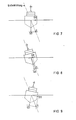
- FIG. 5 shows the ship 1 and the axes of the coordinate system in the same position as in FIG. 4, but now the isolines 12 of the magnetic field are shown in the case of pure longitudinal magnetization of the ship 1.
- a measurement of the vertical field component would have the basic course marked with 13 below the ship 1.
- FIG. 6 shows the ship 1 in a front view and correspondingly the y and z axes of the coordinate system.
- lines 14 of the same field strength are entered schematically with pure transverse magnetization of ship 1. If one measures the vertical component of the magnetic field with such a magnetization in the depth MT, the field course marked with 15 would result.
- a ship 1 Under normal circumstances, a ship 1 has both vertical and longitudinal and transverse magnetizations, i.e. in all three coordinate directions.
- the Z component of the ship's field created in this way is independent of the heading angle.
- the X component changes depending on the exchange rate according to a cosine function, which has its maximum value at the north and south rate and is zero at the east and west rate.
- the Y component also changes depending on the course, but according to a sine function which has its maximum value at the east and west course and is zero at the north and south course. All three components also change their value when the ship lurches and rams.
- the induced interference field components during lurching are shown in more detail in FIGS. 7-9. In the direction of its total, the earth's magnetic field generates the induced field vector S, which is divided into the components SZI and SYI according to the crossing angle of the ship 1.
- the coils are in turn named according to their main magnetic directions of action.
- the coils 2 according to FIG. 1, which are parallel to the YZ plane, are the L coils (L-MES winding), whose magnetic axes of action lie in the longitudinal direction of the ship (L corresponds to the longitudinal direction).
- the coils 3 according to FIG 2 (only one is shown), which are parallel to the XY plane, are the V-coils (V-MES winding) with vertical magnetic axes of action (V corresponds to vertical).
- V-MES winding V-coils with vertical magnetic axes of action (V corresponds to vertical).
- A-coils A-MES winding whose magnetic direction of action lies in the Y-direction (A corresponds to athwort-ship).
- each coil 2 or 3 or 4 consists of three sub-coils with the additional ranges P, I, E
- an MES system has windings (sub-coils) referred to below: VI vertically acting induced field winding VP vertical field permanent winding VE vertically acting eddy current field winding LI longitudinal field-acting induced field winding LP fore and aft permanent field winding LE longitudinal eddy current field winding AI Inducted field winding acting across the ship AP transversal permanent field winding AE transversal eddy current field winding
- the coil windings are fed with direct currents in different directions.
- the positive current directions result from the positive directions of the X-Y-Z coordinate system shown in FIG.
- the currents are set and the windings are switched so that the magnetic field of the hull, the so-called interference field, is optimally compensated for.
- a controller or controller ensures that the set compensation is retained.
- FIG. 5 corresponds to the coil system consisting of coils 2-4 and 6 represents the vehicle equipped with sensors (ship 1).
- 7 denotes a measured value memory containing the current measured values and 8 denotes a database in which generally and long-term valid ones Data are stored.
- the measurement value memory 7 and the data 8 supplied to control values for the coil system 5 processed.
- the measured value memory 7 receives the current measured values from the measured value transmitters of the vehicle 6, whereby these measured value transmitters are not external magnetic field probes, but only transmitters for the detection of movements and the location of the vehicle.
- the hardware core is an intelligent control system, the data processor 9 of which is fed into the coil system 5 of the vehicle by means of an integrated control and regulating method and a database 8 of fixed parameters and measured influencing variables (measured value memory 7) 6 controls based on a predetermined sequence control (control algorithms) so that optimal compensation is guaranteed.
- the control and regulation procedure is to be used on vehicles with an amagnetic outer skin, on vehicles with a non-magnetic but electrically conductive outer skin and on vehicles with a ferromagnetic outer skin.
- All the data that the process-controlled MES system requires for the control to achieve optimal compensation are stored in the database 8 or are determined inside the vehicle 6 by sensors that are not magnetic field probes.
- the data in the database 8 are subdivided into data that are valid for all vehicles (generally valid data) and data that are typical of the vehicle and that apply for the long term.
- the geographic data are valid for all vehicles.
- the specific data of a vehicle are determined during the initial measurement. They show the dependency between the coil system 5 of the vehicle 6 in question and the influences of the earth field components.
- the data processor 9 polls the influencing variables with a continuously running measuring program and thus supplies the control algorithms via the measured value memory 7 with the current data which are necessary for determining an optimal MES setting.
- Groups 1 and 2 are general and long-term data and are therefore stored in database 8.
- Group 3 is current measurement data and is therefore supplied to the measured value memory 7.
- a constant measuring program runs in the process control of the intelligent control system, which detects the control data from the coil system 5 and the movement data of the vehicle 6 and feeds them to the measured value memory 7.
- the movement data have a priority over the control data in triggering a reaction of the process control.
- the sequence in the transaction data list is as follows: - Course - Swerve - pounding - geographical location
- the movements of lurching or pounding can be recorded either by roller ball encoders or gyro encoders.
- the yaw is detected by a gyro and treated like a course change.
- the induced field Due to the constantly changing position of the vehicle in the earth's field, the induced field is also constantly changing. This also makes it necessary to change the counter-magnetic measures.
- the reactions of the vehicle are through electrically simulated movements during the first measurement under the magnetic conditions of the measuring location have been determined. With the help of the determined reaction parameters and the earth field components of the location, the movement-correct magnetic reaction of the induced field MES becomes a linear control problem.
- the second reaction to movements such as lurching, pounding and yawing is the generation of swirl fields in vehicles with large internals made of conductive material or vehicles which are made entirely or partially of conductive material. Movement in the earth's field creates induction currents in the conductive materials, so-called eddy currents, which in turn generate magnetic fields.
- the swirl fields occur almost 90 ° out of phase and are dependent on the roll and pound frequency.
- the subcomponents P permanent component
- IV the vertical induced field component generated by the vertical earth field component
- IHN the horizontal induced field component generated by the horizontal earth field component on the north course
- IHO the horizontal induced field component generated by the horizontal earth field component on the east course 8th.
- the following information is also required to calculate an interference field of a ferromagnetic object on any course and at any point on earth: - the course angle FI - the vertical proportion of the earth's field at the EVM site - The vertical earth field share at the "computer location” EVR - The horizontal portion of the earth's field at the EHM site - The horizontal earth field share at the "computer location” EHR
- measurement location means the location of the measurement of the vehicle and “computer location” the current location of the vehicle.
- the earth field components are to be specified in a uniform unit of measurement. Which unit is used when specifying the earth field components is irrelevant.
- the vortex fields require their own compensation program, the reaction parameters of which in turn were determined during the initial measurement with electrically simulated movement.
- To simplify the swirl field compensation should be operated with a second processor in master-slave mode.
- the control algorithm intervenes when the motion sensor indicates a movement of the vehicle about its longitudinal and transverse axes.
- the data processor 9 receives the current values of the pounding and rolling movements which are contained in a third and fourth memory sectors 7d and 7e. Via its output 9d, the data processor 9 supplies the necessary control signals for the compensation of the control field caused by the corresponding vehicle movements.
- the effectiveness of the control algorithm by which the roll movements according to FIGS. 7-9 are included in the process-controlled MES system depends on the quality of the setting data (data subgroups 2.5 and 2.6) determined during the initial measurement.
- the components of the self-magnetic field are measured in coordinate directions X, Y and Z and stored.
- the coordinate system is object-fixed for easier handling.
- the component points in the X direction to the bow of the object and thus to the top edge of the matrix, the component in the Y direction to the right of object and matrix, and the component in the Z direction downwards.
- the first step in solving the worldwide interference field calculation of an object is the calculation of the interference field on every course at the measuring location.
- the permanent component P, the vertical induced field IV and the horizontal induced field components on the north or east course IHN and IHO are parameters of the calculation.
- the horizontal induced field portion IHN on the north course behaves like the cos the course angle FI
- the horizontal induced field portion IHO on the east course behaves like the sin of the course angle FI.
- the permanent component P and the vertical induced field component IV caused by the vertical earth field component always remain the same. If the interference field of an object is to be calculated for a location with other geomagnetic conditions than at the measurement location, the horizontal factor HF and the vertical factor VF must be inserted in the calculation specification.
- HST P + (IHN ⁇ COS FI) ⁇ HF + (IHO ⁇ SIN FI) ⁇ HF + IV ⁇ VF
- the subcomponents are taken from the database 8.
- the earth field values of the horizontal and vertical earth field for the measuring location can be firmly agreed in the computer program.
- the earth field components of the locations for which the interference field of the object is to be calculated can also be present in the database 8 if used frequently. An entry for nonexistent data should be provided.
Abstract
Description
Die Erfindung bezieht sich auf eine Vorrichtung zum Steuern einer magnetischen Eigenschutz(MES)-Anlage eines Fahrzeuges, die ein großräumiges dreiachsiges Spulensystem bestehend aus stromdurchflossenen Spulen in drei orthogonalen Fahrzeugachsen zur Kompensation des vom Erdmagnetfeld am Fahrzeugort und der Fahrzeugbewegung im Erdmagnetfeld (Kurs, Schlingern, etc.). abhängigen magnetischen Eigenfeldes des Fahrzeuges aufweist.The invention relates to a device for controlling a magnetic self-protection (MES) system of a vehicle, which has a large-area, three-axis coil system consisting of current-carrying coils in three orthogonal vehicle axes to compensate for the earth's magnetic field at the vehicle location and the vehicle's movement in the earth's magnetic field (course, roll, Etc.). dependent magnetic field of the vehicle.
Schiffe, Boote und andere Fahrzeuge der Bundeswehr, aber auch Handelsschiffe, werden aufgrund ihres magnetischen Eigenfeldes (Störfeld), das sich dem Erdfeld überlagert und dieses verzerrt, von Minen und Torpedos mit magnetischen Sensoren direkt bedroht oder sind durch Ortungssysteme mit magnetischen Sensoren aufzuspüren. Aus diesem Grund sind die zu schützenden Fahrzeuge mit einer MES-Anlage ausgerüstet, die die Aufgabe hat, das magnetische Eigenfeld und damit die Gefährdung, herabzusetzen.Ships, boats and other vehicles of the Bundeswehr, but also merchant ships, are directly threatened by mines and torpedoes with magnetic sensors due to their own magnetic field (interference field), which overlaps and distorts the earth's field, or can be tracked down using magnetic sensors. For this reason, the vehicles to be protected are equipped with an MES system, which has the task of reducing the magnetic field and thus the hazard.
Das magnetische Eigenfeld enthält dabei einen sogenannten Permanentanteil und einen Induziertanteil, der auf die dauernde Aufmagnetisierung des Fahrzeuges beim Fahren im Erdfeld zurückzuführen ist, wobei seine Größe je nach dem Kurs und der Lage der Fahrzeugachsen zum Horizont veränderlich ist.The magnetic self-field contains a so-called permanent component and an induced component, which is due to the permanent magnetization of the vehicle when driving in the earth's field, the size of which varies depending on the course and the position of the vehicle axles to the horizon.
Derartige MES-Anlagen sind in der Literatur hinlänglich beschrieben (z.B. Kosack und Wangerin, "Elektrotechnik auf Handelsschiffen", Springer Verlag 1956, Seite 255-257, Abb.234). Sie weisen ein großräumiges, dreiachsiges Spulensystem, bestehend aus stromdurchflossenen Spulen in drei orthogonalen Achsen zur Kompensation des magnetischen Eigenfeldes des Fahrzeuges, auf.Such MES systems are well described in the literature (e.g. Kosack and Wangerin, "Electrical engineering on merchant ships", Springer Verlag 1956, pages 255-257, Fig. 234). They have a large, three-axis coil system consisting of coils through which current flows in three orthogonal axes to compensate for the vehicle's own magnetic field.
Jedes mit einer MES-Anlage ausgerüstete Fahrzeug erfährt zunächst aufgrund einer sogenannten magnetischen Vermessung eine Grundeinstellung der MES-Anlage (Erstvermessung), bei der durch Einstellen geeigneter Wicklungsströme und geeigneter Spulenschaltzustände (Amperewindungszahlen) ein optimaler Kompensationswert erreicht wird.Every vehicle equipped with an MES system first experiences a basic setting of the MES system (initial measurement) based on a so-called magnetic measurement, in which an optimal compensation value is achieved by setting suitable winding currents and suitable coil switching states (ampere-turn numbers).
Die Einstellung ändert sich jedoch - abgesehen von Langzeitveränderungen, die in gewissen Zeitabständen eine Einstellungskontrolle erfordern - im Fahrbetrieb. Infolge der
- Breitenabhängigkeit des Erdmagnetfeldes
- Kursabhängigkeit des von der Horizontalkomponente des Erdmagnetfeldes erzeugten Induziertanteiles
- Abhängigkeit des Induziertfeldes von der Lage der Fahrzeugachsen zum Horizont
weist die MES-Anlage eine Regeleinrichtung bzw. eine Steuerung auf, die die Ströme bzw. durch Schalten von Windungen die Amperewindungszahlen in den einzelnen Spulen im Fahrbetrieb so nachstellt, daß die eingestellte Kompensation des Störfeldes erhalten bleibt.However, the setting changes - apart from long-term changes that require a setting check at certain intervals - while driving. As a result of
- Dependence on latitude of the earth's magnetic field
- Course dependency of the induced portion generated by the horizontal component of the earth's magnetic field
- Dependence of the induced field on the position of the vehicle axles to the horizon
the MES system has a regulating device or a controller which adjusts the currents or, by switching windings, the ampere-turn numbers in the individual coils during driving so that the set compensation of the interference field is retained.
Es ist bekannt, einen Hand-Breitengradregler und einen sowohl von Hand als auch selbsttätig durch den Kreiselkompaß betätigbaren Kursausgleichregler vorzusehen (Deutsche Minenräumdienstvorschrift Nr.16 "Magnetischer Schutz der Minenräumfahrzeuge, 1946 insbesondere Seite 14/15).It is known to provide a manual latitude controller and a course compensation controller which can be operated both manually and automatically by the gyrocompass (German mine clearance regulation No. 16 "Magnetic protection of the mine clearance vehicles, 1946 in
Die Kreisel-MES-Anlage ist jedoch in der Praxis eine Handsteuerung. Fehler in der Bedienung der Regler werden daher nur durch manuelle Kontrolle erkannt. Zudem werden bei der bekannten Anlage die Eigenfeldänderungen nicht erfaßt. Die bekannte MES-Anlage kann daher im Hinblick auf die gesteigerte Empfindlichkeit der Zünder heutigen Ansprüche nicht mehr genügen.In practice, however, the Gyro MES system is a manual control. Errors in the operation of the controllers are therefore only recognized by manual control. In addition, the eigenfield changes are not recorded in the known system. The known MES system can therefore no longer meet today's requirements with regard to the increased sensitivity of the detonators.
Es ist auch bekannt, durch magnetische Fühlorgane (Sensoren) die Änderungen des Schiffs- und Erdfeldes zu erfassen (Kosack und Wangerin v.g. S.257). Diese vollautomatischen, sondengesteuerten, stromgeregelten MES-Anlagen weisen heute üblicherweise ein schiffsfest montiertes Magnetfeldsondentripel zur Erfassung des Erdfeldes am Schiffsort und der Schiffsbewegungen im Erdfeld (Kurs, Schlingern, Stampfen, Gieren) auf (DE-PS 977 846). Es erfolgt dabei eine getrennte Kompensation der Permanent-, Induziert- und Wirbelstrom-Komponenten des Schiffsstörfeldes in allen drei Schiffsachsen (Vertikal-, Horizontal- und Querschiff).It is also known to use magnetic sensing elements (sensors) to detect changes in the ship and earth field (Kosack and Wangerin v.g. p.257). These fully automatic, probe-controlled, current-controlled MES systems today usually have a magnetic field probe triplet mounted fixed to the ship to record the earth's field at the ship's location and ship movements in the earth's field (course, lurching, pounding, yawing) (DE-PS 977 846). There is a separate compensation of the permanent, induced and eddy current components of the ship interference field in all three ship axes (vertical, horizontal and transept).
Diese bekannte MES-Anlage besitzt folgende Nachteile:
Die Sondenanlage, das Sonden-Tripel, kann aus technischen Gründen am Fahrzeug nicht am Ort für die günstigste Messung mit optimalen Meßbedingungen angebracht werden, sondern nur dort, wo es baulich möglich ist.This known MES system has the following disadvantages:
For technical reasons, the probe system, the probe triple, cannot be attached to the vehicle for the cheapest measurement with optimal measuring conditions, but only where it is structurally possible.
Das Meßsignal der Sonden im Erdfeld ist das alleinige Regelsignal für die MES-Anlage. Beim Total-Ausfall der Sonden kann die Anlage daher nur von Hand gefahren werden, wobei die sogenannten MES-Kanäle kursabhängig gesteuert werden. Sondenfehler werden nicht leicht bemerkt.The measurement signal of the probes in the earth's field is the sole control signal for the MES system. In the event of total failure of the probes, the system can therefore only be operated by hand, the so-called MES channels being controlled depending on the course. Probe errors are not easily noticed.
Wird das Meßsignal nicht vom Erdfeld, sondern vom Schiffsfeld erzeugt, ist die Fehlererkennung noch wesentlich schwieriger und führt noch eher zu einer Fehlinterpretation und damit zu einer fehlerhaften MES-Einstellung.If the measurement signal is not generated by the earth's field, but by the ship's field, error detection is even more difficult and leads more to a misinterpretation and thus to an incorrect MES setting.
Durch die Weiterentwicklung der Sensortechnik ist dabei eine Situation entstanden, in der nicht ausreichende magnetische Schutzmaßnahmen einerseits eine trügerische Sicherheit vorgaukeln, dem intelligenten Sensor aber andererseits die Möglichkeit geben, genauer "zu treffen".The further development of sensor technology has created a situation in which insufficient magnetic protection measures on the one hand pretend that the security is deceptive, but on the other hand give the intelligent sensor the opportunity to "hit" more precisely.
Es ist also erforderlich, die Wirkung der MES-Anlage der Sensorentwicklung anzupassen. Diese Forderung gilt sowohl für Fahrzeuge in ferromagnetischer Bauweise als auch für Fahrzeuge in amagnetischer Bauweise mit teilweise ferromagnetischen Einbauten.It is therefore necessary to adapt the effect of the MES system to the sensor development. This requirement applies both to vehicles in ferromagnetic construction and to vehicles in non-magnetic construction with partially ferromagnetic internals.
Der Erfindung liegt daher die Aufgabe zugrunde, die eingangs bezeichnete Vorrichtung so weiterzubilden, daß sie eine wesentlich bessere und zuverlässigere magnetische Kompensation von Fahrzeugen liefert als die Kompensation mit herkömmlichen MES-Steuerungen. Es gilt einen optimalen magnetischen Schutzzustand zu erreichen und die Vermessung und Kontrolle des magnetischen Schutzzustandes von außen auf ein Minimum zu beschränken, um damit gleichzeitig die Betriebssicherheit der Anlage wesentlich zu steigern.The invention is therefore based on the object of developing the device described at the outset in such a way that it provides substantially better and more reliable magnetic compensation for vehicles than the compensation with conventional MES controls. It is important to achieve an optimal magnetic protection state and to limit the measurement and control of the magnetic protection state from the outside to a minimum in order to increase the operational safety of the system at the same time.
Die Erfindung soll dabei auf hochgeschützten Fahrzeugen mit amagnetischer und elektrisch nicht leitender Außenhaut, auf hochgeschützen Fahrzeugen mit amagnetischer, aber elektrisch leitender Außenhaut und auf Fahrzeugen mit ferromagnetischer Außenhaut eingesetzt werden können.The invention is intended to be able to be used on highly protected vehicles with an amagnetic and electrically non-conductive outer skin, on highly protected vehicles with a non-magnetic but electrically conductive outer skin and on vehicles with a ferromagnetic outer skin.
Die Lösung dieser Aufgabe gelingt gemäß der Erfindung dadurch, daß eine Prozeßsteuerung mit einem digitalen Datenprozessor vorgesehen ist,
dem eine Datenbank zugeordnet ist, in der
- fahrzeugspezifische Daten der Erstvermessung am Meßort
- standortabhängige Daten über die erdmagnetischen Verhältnisse im Operationsgebiet des Fahrzeuges (geomagnetische Daten)
abgelegt sind,
dem an Bord des Fahrzeuges befindliche Meßgeber für Spulendaten, geomagnetischer Standort, Kurs- und Fahrzeugeigenbewegungen zugeordnet sind und
der aufgrund einer vorgegebenen Ablaufsteuerung (Algorithmen) die Amperewindungszahlen der Kompensationsspulen so steuert, daß eine optimale Kompensation gewährleistet ist.This object is achieved according to the invention in that process control with a digital data processor is provided,
to which a database is assigned in which
- Vehicle-specific data of the first measurement at the measuring location
- Location-dependent data on the geomagnetic conditions in the operating area of the vehicle (geomagnetic data)
are filed,
the on-board sensor for coil data, geomagnetic location, course and vehicle movements are assigned and
which controls the number of ampere turns of the compensation coils based on a predetermined sequence control (algorithms) in such a way that optimal compensation is ensured.
Bei der erfindungsgemäßen Vorrichtung einer prozeßgesteuerten MES-Anlage werden die magnetischen Gegenfelder zur Kompensation der am oder im Fahrzeug auftretenden magnetischen Wirkungen abhängig vom geographischen Standort, vom Kurs und von der Fahrzeugeigenbewegung gesteuert. Kernstück der prozeßgesteuerten MES-Anlage ist eine intelligente Steueranlage mit einem Daten-Prozessor, der auf eine Datenhaltung (Datenbank) zurückgreift.In the device according to the invention of a process-controlled MES system, the magnetic opposing fields to compensate for the magnetic effects occurring on or in the vehicle are controlled as a function of the geographical location, the course and the vehicle's own movement. The heart of the process-controlled MES system is an intelligent control system with a data processor that uses data storage (database).
In der Datenhaltung sind die Parameter enthalten, die benötigt werden, um eine optimale Steuerung der MES-Anlage zu erreichen. Es sind die Daten für die Kompensation
- der standortabhängigen magnetischen Effekte
- der standort- und kursabhängigen magnetischen Effekte
- der von den Eigenbewegungen des Fahrzeuges im Erdfeld abhängigen magnetischen Effekte
- der von Betriebszuständen abhängigen magnetischen Effekte.The data storage contains the parameters that are required to achieve optimal control of the MES system. It is the data for the compensation
- the location-dependent magnetic effects
- The location and course-dependent magnetic effects
- The magnetic effects dependent on the vehicle's own movements in the earth's field
- The magnetic effects depending on operating conditions.
Die magnetischen Felder von ferromagnetischen Objekten wie Einbauten und Ausrüstungsgegenstände der Fahrzeuge sowie ihre magnetische Reaktion bei unterschiedlichen Betriebszuständen und bei Bewegung im Erdfeld, lassen sich dabei meßtechnisch genau erfassen. Dieses gilt auch für die ferromagnetische oder amagnetische Außenhaut des Fahrzeuges. Ebenso einfach sind mit bekannten, im Fahrzeuginneren angeordneten Datengebern - unter Verzicht auf Magnetfeldsonden - die Daten über den Kurs, Standort und Eigenbewegung des Fahrzeuges zu ermitteln.The magnetic fields of ferromagnetic objects such as internals and equipment in vehicles as well as their magnetic reaction in different operating states and when moving in the earth's field can be measured precisely. This also applies to the ferromagnetic or non-magnetic outer skin of the vehicle. With known data transmitters arranged inside the vehicle - without magnetic field probes - it is just as easy to determine the data about the course, location and own movement of the vehicle.
Weiterhin sind die Daten für die Steuerung der MES-Anlage in Ausnahmesituationen abgelegt, so daß auch für eine gestörte Anlage eine möglichst optimale Einstellung gewährleistet ist.Furthermore, the data for the control of the MES system are stored in exceptional situations, so that the best possible setting is guaranteed even for a faulty system.
Bei der erfindungsgemäß ausgebildeten Vorrichtung werden die bislang über Magnetfeldsonden erlangten Daten für die Regelung bzw. Steuerung der Amperewindungszahlen der Kompensationsspulen über die gespeicherten geometrischen Daten in Verbindung mit Meßwerten über den geographischen Standort und direkte Messung der Fahrzeugeigenbewegung sowie der Betriebszustände durch entsprechende Geber im Fahrzeuginneren gemessen.In the device designed according to the invention, the data previously obtained via magnetic field probes for the regulation or control of the ampere-turn numbers of the compensation coils are measured using the stored geometric data in conjunction with measured values relating to the geographical location and direct measurement of the vehicle's own movement and the operating states by corresponding sensors inside the vehicle.
Der große Vorteil der erfindungsgemäßen Vorrichtung liegt darin, daß auf eine mechanisch sehr leicht zu beschädigende Magnetfeldsondenanlage verzichtet werden kann, wodurch die Betriebssicherheit beträchtlich gesteigert werden kann. Der Schwerpunkt liegt nicht mehr in der Messung und komplizierten Kompensation von Sondensignalen, sondern in der eigentlichen Regelung/Steuerung, mit einer ständigen digitalen Kontrolle. Es ist die Berücksichtigung von Betriebszuständen ohne den Umweg über die Sondenreaktion gegeben. Die Kompensation ist daher optimal durchzuführen. Die prozeßgesteuerte MES-Anlage hat dabei besonders gute Einsatzmöglichkeiten bzw. Vorteile an Unterwasserfahrzeugen, da es stets problemhaft ist, die Magenetfeldsonden am Außenkörper der U-Boote an exponierter Stelle anzubringen.The great advantage of the device according to the invention is that there is no need for a magnetic field probe system which is mechanically very easily damaged, as a result of which operational reliability can be increased considerably. The focus is no longer on the measurement and complicated compensation of probe signals, but on the actual regulation / control, with constant digital control. Operating states are taken into account without the detour via the probe reaction. The compensation must therefore be carried out optimally. The process-controlled MES system has particularly good uses or advantages on underwater vehicles, since it is always problematic to attach the gastro-field probes to the outer body of the submarines at an exposed point.
Weltweite Einsatzmöglichkeit, geringere Störanfälligkeit und besserer Schutz gegen Magnetsensoren zeichnen dabei die Fahrzeuge, die mit der erfindungsgemäßen Vorrichtung ausgerüstet sind, aus.Worldwide use, less susceptibility to malfunction and better protection against magnetic sensors distinguish the vehicles which are equipped with the device according to the invention.
Anhand eines in den Zeichnungen dargestellten Ausführungsbeispieles wird die Erfindung näher erläutert. Es zeigen:
- FIG 1 bis 3 das Spulensystem einer MES-Anlage in einem Schiffskörper,
- FIG 4 bis 6 die magnetischen Schiffseigenfelder (Störfelder) in den drei Schiffskoordinaten,
- FIG 7 bis 9 die Größen der Induziertanteile beim Schlingern des Schiffes,
- FIG 10 ein Blockdiagramm der erfindungsgemäßen prozeßgesteuerten MES-Anlage,
- FIG 11 bis 14 die schematische Darstellung des Informationsflusses bei der Kompensation mit vier unterschiedlichen Kompensations-Algorithmen.
- 1 to 3 the coil system of an MES system in a hull,
- 4 to 6 show the magnetic fields of the ship (interference fields) in the three ship coordinates,
- 7 to 9 show the sizes of the induced portions when the ship lurches,
- 10 shows a block diagram of the process-controlled MES system according to the invention,
- 11 to 14 the schematic representation of the information flow in the compensation with four different compensation algorithms.
In den FIG 1-3 ist das großräumige, dreiachsige Spulensystem einer MES-Anlage eines Schiffes 1 (als Beispiel eines Fahrzeuges als ferromagnetischer Störkörper) dargestellt. Dieses Spulensystem besteht aus Spulen 2,3,4 in den drei orthogonalen Achsen X-Y-Z. Jede Spule 2 bzw.3 bzw.4 ist üblicherweise in drei - nicht mehr näher dargestellte - Teilspulen aufgeteilt. Die eine Teilspule (Zusatzbezeichnung P) dient zur Kompensation eines permanenten fahrzeugabhängigen Störfeldanteiles. Eine zweite Teilspule (Zusatzbezeichnung I) dient zur Kompensation eines vom Erdfeld induzierten Störfeldanteiles.
Da als Folge der Eigenbewegung des Schiffes 1 im Erdfeld in metallischen Teilen des Systems Wirbelfelder induziert werden, erfolgt deren Kompensation mit einer dritten Teilspule (Zusatzbezeichnung E).1-3 shows the large-scale, three-axis coil system of an MES system of a ship 1 (as an example of a vehicle as a ferromagnetic interference body). This coil system consists of
Since vortex fields are induced in metallic parts of the system as a result of the ship 1's own movement in the earth's field, it is compensated for with a third coil section (additional designation E).
Die magnetischen Schiffsfelder - die in den FIG 4-6 dargestellt sind - werden üblicherweise nach den Schiffskoordinaten wie folgt bezeichnet:
Längsschiffkomponente = X-Komponente (FIG 5)
Querschiffskomponente = Y-Komponente (FIG 6)
Vertikale Komponente = Z-Komponente (FIG 4)
Das X-Y-Z-Koordinatensystem wird als objektfest angenommen, d.h. ist auf den Erzeuger des magnetischen Störfeldes - im Ausführungsbeispiel das Schiff 1 - ausgerichtet.The magnetic ship fields - which are shown in FIGS. 4-6 - are usually designated as follows according to the ship coordinates:
Longitudinal ship component = X component (FIG 5)
Transept component = Y component (FIG 6)
Vertical component = Z component (FIG 4)
The XYZ coordinate system is assumed to be fixed to the object, ie it is oriented towards the generator of the magnetic interference field - in the exemplary embodiment ship 1.
FIG 4 zeigt das Schiff mit dem objektfesten Koordinatensystem. Zusätzlich sind in schematischer Form die Isolinien 10 des Magnetfeldes bei rein vertikaler Magnetisierung des Schiffes 1 eingetragen. Eine Messung des vertikalen Feldanteiles in der Wassertiefe MT ergäbe den mit 11 gekennzeichneten prinzipiellen Verlauf unterhalb des Schiffes.4 shows the ship with the object-fixed coordinate system. In addition, the
FIG 5 zeigt das Schiff 1 und die Achsen des Koordinatensystems in der gleichen Lage wie in FIG 4, jedoch sind nun die Isolinien 12 des Magnetfeldes bei reiner Längsmagnetisierung des Schiffes 1 dargestellt. Eine Messung des vertikalen Feldanteiles würde den mit 13 gekennzeichneten prinzipiellen Verlauf unterhalb des Schiffes 1 aufweisen.FIG. 5 shows the ship 1 and the axes of the coordinate system in the same position as in FIG. 4, but now the
In FIG 6 ist das Schiff 1 in Frontansicht und entsprechend die y- und z-Achse des Koordinatensystems dargestellt. Dazu sind schematisch die Linien 14 gleicher Feldstärke bei reiner Quermagnetisierung des Schiffes 1 eingetragen. Mißt man bei einer solchen Magnetisierung in der Tiefe MT die vertikale Komponente des Magnetfeldes, so würde sich der mit 15 gekennzeichnete Feldverlauf ergeben.6 shows the ship 1 in a front view and correspondingly the y and z axes of the coordinate system. For this purpose, lines 14 of the same field strength are entered schematically with pure transverse magnetization of ship 1. If one measures the vertical component of the magnetic field with such a magnetization in the depth MT, the field course marked with 15 would result.
Unter normalen Umständen weist ein Schiff 1 sowohl vertikale als auch Längs- und Quermagnetisierungen, d.h. in allen drei Koordinatenrichtungen, auf.Under normal circumstances, a ship 1 has both vertical and longitudinal and transverse magnetizations, i.e. in all three coordinate directions.
Die Z-Komponente des dadurch erzeugten Schiffsfeldes ist unabhängig vom Kurswinkel. Die X-Komponente ändert sich kursabhängig nach einer Cosinus-Funktion, die ihren Höchstwert bei Nord- und Südkurs hat und bei Ost- und Westkurs Null ist. Die Y-Komponente ändert sich gleichfalls kursabhängig, jedoch nach einer Sinus-Funktion, die ihren Höchstwert bei Ost- und Westkurs hat und bei Nord-und Südkurs Null ist. Alle drei Komponenten verändern ihren Wert zusätzlich noch bei Schlinger- und Stampfbewegungen des Schiffes. Die Induziert-Störfeldanteile beim Schlingern sind dabei in den FIG 7-9 näher dargestellt. Das Erdmagnetfeld erzeugt in der Richtung seiner Totalen den Induziertfeldvektor S, der sich entsprechend dem Kreuzungswinkel des Schiffes 1 in die Komponenten SZI und SYI aufteilt.The Z component of the ship's field created in this way is independent of the heading angle. The X component changes depending on the exchange rate according to a cosine function, which has its maximum value at the north and south rate and is zero at the east and west rate. The Y component also changes depending on the course, but according to a sine function which has its maximum value at the east and west course and is zero at the north and south course. All three components also change their value when the ship lurches and rams. The induced interference field components during lurching are shown in more detail in FIGS. 7-9. In the direction of its total, the earth's magnetic field generates the induced field vector S, which is divided into the components SZI and SYI according to the crossing angle of the ship 1.
Die Spulen wiederum werden entsprechend ihren magnetischen Hauptwirkungsrichtungen bezeichnet. Die Spulen 2 nach FIG 1, die parallel zur Y-Z-Ebene liegen, sind die L-Spulen (L-MES-Wicklung), deren magnetische Wirkungsachsen in der Schiffslängsrichtung liegen (L entspricht longitudinal).
Die Spulen 3 nach FIG 2 (nur eine ist dargestellt), die parallel zur X-Y-Ebene liegen, sind die V-Spulen (V-MES-Wicklung) mit vertikalen magnetischen Wirkungsachsen (V entspricht vertikal).
Die Spulen 4 nach FIG 3, die parallel zu oder in der X-Z-Ebene liegen, sind die A-Spulen (A-MES-Wicklung) deren magnetische Wirkungsrichtung in Y-Richtung liegt (A entspricht athwort-ship).The coils are in turn named according to their main magnetic directions of action. The coils 2 according to FIG. 1, which are parallel to the YZ plane, are the L coils (L-MES winding), whose magnetic axes of action lie in the longitudinal direction of the ship (L corresponds to the longitudinal direction).
The
3, which are parallel to or in the XZ plane, are the A-coils (A-MES winding) whose magnetic direction of action lies in the Y-direction (A corresponds to athwort-ship).
Da, wie erwähnt, jede Spule 2 bzw.3 bzw.4 aus drei Teilspulen mit den Zusatzbereichnunen P,I,E besteht, weist eine MES-Anlage nachstehend bezeichnete Wicklungen (Teilspulen) auf:
VI vertikalwirkende Induziertfeldwicklung
VP vertikalwirkende Permanentfeldwicklung
VE vertikalwirkende Wirbelstromfeldwicklung
LI längsschiffwirkende Induziertfeldwicklung
LP längsschiffwirkende Permanentfeldwicklung
LE längsschiffwirkende Wirbelstromfeldwicklung
AI querschiffwirkende Induziertfeldwicklung
AP querschiffwirkende Permanentfeldwicklung
AE querschiffwirkende WirbelstromfeldwicklungSince, as mentioned, each
VI vertically acting induced field winding
VP vertical field permanent winding
VE vertically acting eddy current field winding
LI longitudinal field-acting induced field winding
LP fore and aft permanent field winding
LE longitudinal eddy current field winding
AI Inducted field winding acting across the ship
AP transversal permanent field winding
AE transversal eddy current field winding
Die Spulenwicklungen werden mit Gleichströmen in unterschiedlichen Richtungen beschickt. Die positiven Stromrichtungen resultieren dabei aus den positiven Richtungen des in FIG 1 dargestellten Koordinatensystems X-Y-Z.The coil windings are fed with direct currents in different directions. The positive current directions result from the positive directions of the X-Y-Z coordinate system shown in FIG.
Bei der Ersteinstellung und bei Einstellungskontrollen (magnetische Vermessung) werden die Ströme so eingestellt und die Wicklungen so geschaltet, daß das magnetische Eigenfeld des Schiffskörpers, das sogenannte Störfeld, möglichst optimal kompensiert wird. Im laufenden Betrieb (Fahrt) sorgt ein Regler bzw. eine Steuerung dafür, daß die eingestellte Kompensation erhalten bleibt.During the initial setting and during setting checks (magnetic measurement), the currents are set and the windings are switched so that the magnetic field of the hull, the so-called interference field, is optimally compensated for. During operation (travel), a controller or controller ensures that the set compensation is retained.
In FIG 10 ist das Grundprinzip der erfindungsgemäßen Vorrichtung in einem Blockdiagramm schematisch dargestellt. In diesem Blockdiagramm entspricht 5 dem aus den Spulen 2-4 bestehenden Spulensystem und 6 stellt das mit Meßwertgebern ausgerüstete Fahrzeug (Schiff 1) dar. Mit 7 ist ein die aktuellen Meßwerte enthaltender Meßwertspeicher und mit 8 eine Datenbank bezeichnet, in der allgemein und langfristig geltende Daten gespeichert sind. In einem Datenprozessor 9 werden die von dem Meß wertspeicher 7 und der Datenbank 8 gelieferten Daten zu Steuerwerten für das Spulensystem 5 verarbeitet. Der Meßwertspeicher 7 erhält die aktuellen Meßwerte von den Meßwertgebern des Fahrzeuges 6 zugeführt, wobei diese Meßwertgeber keine äußeren Magnetfeldsonden sind, sondern lediglich Geber für die Erfassung von Bewegungen und des Standortes des Fahrzeuges.The basic principle of the device according to the invention is shown schematically in a block diagram in FIG. In this block diagram, 5 corresponds to the coil system consisting of coils 2-4 and 6 represents the vehicle equipped with sensors (ship 1). 7 denotes a measured value memory containing the current measured values and 8 denotes a database in which generally and long-term valid ones Data are stored. In a
Bei der erfindungsgemäß prozeßgesteuerten MES-Anlage ist das Hardware-Kernstück eine intelligente Steueranlage, deren Datenprozessor 9 mit Hilfe eines integrierten Kontroll- und Regelverfahrens und einer Datenbank 8 von fest vorgegebenen Parametern und gemessenen Einflußgrößen (Meßwertspeicher 7) die Stromeinspeisung in das Spulensystem 5 des Fahrzeuges 6 aufgrund einer vorgegebenen Ablaufsteuerung (Steueralgorithmen) so steuert, daß eine optimale Kompensation gewährleistet ist. Das Kontroll- und Regelverfahren soll dabei auf Fahrzeugen mit amagnetischer Außenhaut, auf Fahrzeugen mit amagnetischer, aber elektrisch leitender Außenhaut und auf Fahrzeugen mit ferromagnetischer Außenhaut seine Anwendung finden.In the process-controlled MES system according to the invention, the hardware core is an intelligent control system, the
Alle Daten, die die prozeßgesteuerte MES-Anlage für die Steuerung zum Erreichen einer optimalen Kompensation benötigt, sind in der Datenbank 8 abgespeichert bzw. werden durch Geber, die keine Magnetfeldsonden sind, im Innern des Fahrzeuges 6 ermittelt. Die Daten in der Datenbank 8 sind in für alle Fahrzeuge gültige Daten (allgemein gültige Daten) und in Daten, die fahrzeug-typisch sind und langfristig gelten, unterteilt. Für alle Fahrzeuge gültig sind die geopraphischen Daten. Die spezifischen Daten eines Fahrzeuges werden bei der Erstvermessung ermittelt. Sie ergeben die Abhängigkeit zwischen dem Spulensystem 5 des betreffenden Fahrzeuges 6 und den Einflüssen der Erdfeldkomponenten wieder.All the data that the process-controlled MES system requires for the control to achieve optimal compensation are stored in the database 8 or are determined inside the
Mit einem dauernd laufenden Meßprogramm werden vom Datenprozessor 9 die Geber der Einflußgrößen abgefragt und damit den Steuer-Algorithmen über den Meßwertspeicher 7 die aktuellen Daten zugeführt, die zur Ermittlung einer optimalen MES-Einstellung notwendig sind.The
Die Daten, die die intelligente Steueranlage der prozeßgesteuerten MES-Anlage benötigt sind in drei Gruppen unterteilt. Gruppe 1 und 2 sind allgemein und langfristig gültige Daten und somit in der Datenbank 8 abgelegt. Die Gruppe 3 sind aktuelle Meßdaten und werden daher dem Meßwertspeicher 7 zugeführt.The data that the intelligent control system of the process-controlled MES system requires are divided into three groups. Groups 1 and 2 are general and long-term data and are therefore stored in database 8.
Jede Gruppe enthält wiederum systematisch untergliederte Daten-Teilgruppen. Die Datengruppen lassen sich daher wie folgt darstellen:
- 1. Gruppe: Geomagnetische Daten (in Datenbank 8)
- 1.1 Standortbereich 1 des Fahrzeuges
- 1.1.1 Horizontales Erdfeld
- 1.1.2 Vertikales Erdfeld
- 1.1.3 Inklinationswinkel
- 1.2 Standortbereich 2 des Fahrzeuges
- 1.1 Standortbereich 1 des Fahrzeuges
- 2. Gruppe: Daten die bei der Erstvermessung ermittelt wurden (in Datenbank 8)
- 2.1 Kompensation des Permanentfeldes
- 2.1.1 Strom und Schaltung aller LP-Spulen
- 2.1.2 Strom und Schaltung aller AP-Spulen
- 2.1.3 Strom und Schaltung aller VP-Spulen
- 2.2 Kompensation des vertikalen Induziertfeldes IV am Meßort
- 2.2.1 Strom und Schaltung aller VI-Spulen
- 2.3 Kompensation des horizontalen Induziertfeldes IH am Meßort auf Nordkurs (N)
- 2.3.1 Strom und Schaltung aller LI-Spulen
- 2.3.2 Strom und Schaltung aller AI-Spulen
- 2.4 Kompensation des horizontalen Induziertfeldes IH am Meßort auf Ostkurs (O)
- 2.4.1 Strom und Schaltung aller LI-Spulen
- 2.4.2 Strom und Schaltung aller AI-Spulen
- 2.5 Kompensation des Wirbelstromfeldes beim Schlingern am Meßort auf Ostkurs
- 2.5.1 Strom und Schaltung aller AE-Spulen
- 2.5.2 Strom und Schaltung aller VE-Spulen
- 2.6 Kompensation des Wirbelstromfeldes beim Stampfen am Meßort auf Nordkurs
- 2.6.1 Strom und Schaltung aller LE-Spulen
- 2.1 Kompensation des Permanentfeldes
- 3. Gruppe: Daten die an Bord des Fahrzeuges gemessen werden (in Meßwertspeicher 7)
- 3.1 Kontrolldaten aus der Spulenanlage
- 3.1.1 Spulenströme
- 3.1.2 Spulenwärme
- 3.1.3 Spulenwiderstandswerte
- 3.2 Bewegungsdaten
- 3.2.1 Geographischer Standort
- 3.2.2 Kurs
- 3.2.3 Schlingerbewegung
- 3.2.4 Stampfbewegung
- 3.1 Kontrolldaten aus der Spulenanlage
- 1st group: Geomagnetic data (in database 8)
- 1.1 Location area 1 of the vehicle
- 1.1.1 Horizontal earth field
- 1.1.2 Vertical earth field
- 1.1.3 Inclination angle
- 1.2 Location area 2 of the vehicle
- 1.1 Location area 1 of the vehicle
- 2nd group: data determined during the first measurement (in database 8)
- 2.1 Compensation of the permanent field
- 2.1.1 Current and switching of all LP coils
- 2.1.2 Current and switching of all AP coils
- 2.1.3 Current and switching of all VP coils
- 2.2 Compensation of the vertical induced field IV at the measurement location
- 2.2.1 Current and switching of all VI coils
- 2.3 Compensation of the horizontal induced field IH at the measurement location on the north course (N)
- 2.3.1 Current and switching of all LI coils
- 2.3.2 Current and switching of all AI coils
- 2.4 Compensation of the horizontal induced field IH at the measurement location on the east course (O)
- 2.4.1 Current and switching of all LI coils
- 2.4.2 Current and switching of all AI coils
- 2.5 Compensation of the eddy current field when lurching at the measuring location on the east course
- 2.5.1 Current and switching of all AE coils
- 2.5.2 Current and switching of all VE coils
- 2.6 Compensation of the eddy current field when pounding at the measuring location on the north course
- 2.6.1 Current and switching of all LE coils
- 2.1 Compensation of the permanent field
- 3rd group: data measured on board the vehicle (in measured value memory 7)
- 3.1 Control data from the coil system
- 3.1.1 Coil currents
- 3.1.2 Coil heat
- 3.1.3 Coil resistance values
- 3.2 Movement data
- 3.2.1 Geographic location
- 3.2.2 Course
- 3.2.3 Rolling movement
- 3.2.4 Pounding motion
- 3.1 Control data from the coil system
In der Prozeßsteuerung der intelligenten Regelanlage läuft ein ständiges Meßprogramm ab, welches die Kontrolldaten aus dem Spulensystem 5 und die Bewegungsdaten des Fahrzeugs 6 erfaßt und dem Meßwertspeicher 7 zugeführt. Die Bewegungsdaten haben gegenüber den Kontrolldaten im Auslösen einer Reaktion der Prozeßsteuerung eine vorrangige Priorität.A constant measuring program runs in the process control of the intelligent control system, which detects the control data from the
Innerhalb der Bewegungsdatenliste herrscht folgende Reihenfolge:
- Kurs
- Schlingern
- Stampfen
- geographischer StandortThe sequence in the transaction data list is as follows:
- Course
- Swerve
- pounding
- geographical location
In der Ablaufsteuerung des Datenprozessors 9 wird daher auf eine Kursänderung sofort reagiert, dann auf Schlingern und Stampfen und dann erst auf das Erreichen eines anderen geographischen Standortes.In the sequence control of the
Für die Ermittlung der Kompensationen der einzelnen magnetischen Wirkungen laufen quasi parallele Prozesse mit unterschiedlichen Regelalgorithmen ab, die in den FIG 11-14 dargestellt sind.To determine the compensation of the individual magnetic effects, quasi-parallel processes run with different control algorithms, which are shown in FIGS. 11-14.
Die einzelnen Teilwicklungen und ihre Stromeinspeisungen werden danach gemäß folgenden Kriterien behandelt:
- 1) Bei der Kompensation der Permanentanteile sind gemäß FIG 11 nur die Daten der Gruppe 2.1 der Erstvermessung maßgebend. Die eingestellte Kompensation gilt weltweit.
Bei der Kompensation des P-Anteils bleibt für die Regelanlage des MES die Aufgabe, den eingestellten Spulenstrom und die elektrischen Werte des Spulensystems 5 zur P-Kompensation zu kontrollieren. Hierzu enthält der Datenprozessor 9 aus der Datenbank 8 und einem Überwachungssektor 7a des Meßwertspeichers 7 die entsprechenden Werte. Über seinen Steuerausgang 9a kann der Datenprozessor 9 das Spulensystem bei Abweichungen entsprechend nachsteuern. - 2) Die erdmagnetischen Einflüsse auf
das Fahrzeug 6, das Induziertfeld, muß in seine Komponenten zerlegt werden. Da die vertikale und horizontale Komponente IV und IH des Induziertfeldes unterschiedliche Auswirkungen auf den magnetischen Zustand des Fahrzeuges 6 haben, ist ihre Kompensation völlig getrennt vorzunehmen. Das durch die vertikale Komponente des Erdfeldes im Fahrzeug erzeugte vertikale Induziertfeld IV ist zwar standortabhängig, aber nicht kursabhängig. Das durch die horizontale Komponente des Erdfeldes im Fahrzeug erzeugte horizontale Induziertfeld IH dagegen ist standort- und kursabhängig.- a) Bei der Kompensation des verikalen Induziertfeldes IV gemäß FIG 12 greift der Regelalgorithmus daher nur ein, wenn eine Veränderung im geographischen Standort gemessen worden ist.
Der Datenprozessor 9 erhält die zur Berechnung eines Korrektursignals notwendigen Werte von der Datenbank 8 und einem die aktuellen Werte des Standortes bzw. der Standortänderung enthaltenden ersten Speichersektor 7b des Meßwertspeichers 7. Außerdem werden ihmvon dem Überwachungssektor 7a die notwendigen Werte zugeführt. Durch das anseinem Ausgang 9b erscheinende Steuersignal werden die VI-Spulen entsprechend gesteuert. - b) Bei der Kompensation des horizontalen Induziertfeldes IH nach FIG 13 dagegen greift der Regelalgorithmus ein, wenn eine Kursänderung und/oder eine Veränderung im geographischen Standort gemessen worden ist.
Der Datenprozessor 9 erhält hierzu neben den Werten aus der Datenbank 8und dem Überwachungssektor 7a noch die aktuellen Werte ausdem ersten Speichersektor 7b und einem zweitenSpeichersektor 7c, der die Meßwerte für den Kurs bzw. die Kursänderung enthält, zugeführt. Andem Ausgang 9c erscheinen die zur Steuerung notwendigen Steuersignale. Der Regelalgorithmus für die Horizontalkompensation soll auch das Gieren mit abfangen.
- a) Bei der Kompensation des verikalen Induziertfeldes IV gemäß FIG 12 greift der Regelalgorithmus daher nur ein, wenn eine Veränderung im geographischen Standort gemessen worden ist.
- Zur Ermittlung der gegenmagnetischen Maßnahmen gemäß vorstehendem Regelalgorithmus benötigt daher die Prozeßsteuerung der MES-Anlage den Standort und den Kurs des Fahrzeuges. Diese Information erhält die Prozeßsteuerung durch Kopplungen an die den Standort bestimmenden Geräte und den Kreiselkompaß oder im Notfall durch eine manuelle Eingabe. Der Inklinationswinkel und die Horizontalintensität des Erdfeldes und damit auch die Vertikalintensität ändern sich auf der Erde von Ort zu Ort. Im Rahmen der zugelassenen Abweichung von der Idealkompensation durch das Kompensationssystem ist es möglich, die Navigationskarte in Standortbereiche einzuteilen, wobei Isoklinen und Isodynamen bei der Flächeneinteilung zu berücksichtigen sind.
Für diesen Standortbereich ist ein gültiger Horizontalwert und Verikalwert und der Inklinationswinkel festgelegt. Gleichzeitig sollten auch die geographischen magnetischen Anomalien berücksichtigt werden. Die Standortflächenkarte ist als Datei in der Datenbank 8 des MES-Prozessors abgelegt. Die Standortflächen brauchen nicht gleich groß zu sein, aber rechtwinklig unter Berücksichtigung der Längen- und Breitengrade der Navigationskarte eines bestimmten Maßstabes, um die rechnerische Standortflächenbestimmung zu beschleunigen.
Jede Standortfläche mit ihren Eckdaten stellt ein "File" dar. In dieses File werden die Horizontalkomponenten und Vertikalkomponenten des Erdfeldes eingetragen; außerdem die Ströme zur Einspeisung in die Vertikalkompensationsspulen, da die Vertikalkompensation nicht kursabhängig ist.
Für die Horizontalkompensation wird der Strom für eine Nordkurskompensation und eine Ostkurskompensation eingetragen. Aus diesen Werten kann der Strom für die Horizontalkompensation auf jedem Kurswinkel rechnerisch bestimmt werden. - 3) Die bisher angeführten Kompensationsmaßnahmen gegen das Induziertfeld gelten für ein Fahrzeug, welches sich auf einer Ebene bewegt.
Bewegt sich das Fahzeug nicht auf ebenem Kiel, sondern macht das Fahrzeug Bewegungen, die bei einem Schiff mit Schlingern, Stampfen und Gieren bezeichnet werden, so muß die MES-Anlage auf diese Bewegung reagieren.
- 1) According to FIG. 11, only the data of group 2.1 of the first measurement are decisive for the compensation of the permanent components. The compensation set applies worldwide.
When compensating for the P component, the task for the control system of the MES is to check the set coil current and the electrical values of thecoil system 5 for P compensation. For this purpose, thedata processor 9 contains the corresponding values from the database 8 and amonitoring sector 7a of the measured value memory 7. Via itscontrol output 9a, thedata processor 9 can readjust the coil system accordingly in the event of deviations. - 2) The earth's magnetic influences on the
vehicle 6, the induced field, must be broken down into its components. Since the vertical and horizontal components IV and IH of the induced field have different effects on the magnetic state of thevehicle 6, their compensation must be carried out completely separately. The vertical induced field IV generated by the vertical component of the earth field in the vehicle is location-dependent, but not course-dependent. The horizontal induced field IH generated by the horizontal component of the earth field in the vehicle, however, depends on the location and the course.- a) When compensating for the vertical induced field IV according to FIG. 12, the control algorithm therefore only intervenes if a change in the geographic location has been measured. The
data processor 9 receives the values necessary for calculating a correction signal from the database 8 and afirst memory sector 7b of the measured value memory 7 which contains the current values of the location or the change of location. In addition, the necessary values are fed to it by themonitoring sector 7a. The VI coils are controlled accordingly by the control signal appearing at itsoutput 9b. - b) In contrast, when compensating the horizontal induced field IH according to FIG. 13, the control algorithm intervenes when a course change and / or a change in the geographic location has been measured. For this purpose, the
data processor 9 receives, in addition to the values from the database 8 and themonitoring sector 7a, the current values from thefirst memory sector 7b and asecond memory sector 7c, which contains the measured values for the course or the course change. The control signals necessary for control appear at theoutput 9c. The control algorithm for horizontal compensation is also intended to intercept yaw.
- a) When compensating for the vertical induced field IV according to FIG. 12, the control algorithm therefore only intervenes if a change in the geographic location has been measured. The
- To determine the counter-magnetic measures according to the above control algorithm, the process control of the MES system therefore requires the location and the course of the vehicle. The process control receives this information by means of couplings to the devices determining the location and the gyrocompass or, in an emergency, by manual input. The angle of inclination and the horizontal intensity of the earth's field and thus also the vertical intensity change from place to place on earth. As part of the permitted deviation from the ideal compensation by the compensation system, it is possible to divide the navigation map into location areas, whereby isoclinics and isody names must be taken into account when allocating the area.
A valid horizontal value and vertical value and the inclination angle are specified for this location area. At the same time, geographic magnetic anomalies should also be considered. The location area map is stored as a file in database 8 of the MES processor. The location areas do not have to be the same size, but at right angles, taking into account the longitudes and latitudes of the navigation map of a certain scale, in order to accelerate the computational location determination.
Each site area with its key data represents a "file". The horizontal components and vertical components of the earth's field are entered in this file; also the currents for feeding into the vertical compensation coils, since the vertical compensation is not price-dependent.
For the horizontal compensation, the current is entered for a north course compensation and an east course compensation. From these values, the current for horizontal compensation can be determined mathematically at every heading angle. - 3) The above-mentioned compensation measures against the induced field apply to a vehicle that is moving on one level.
If the vehicle does not move on a flat keel, but the vehicle makes movements that are called rolling, pounding and yawing on a ship, the MES system must react to this movement.
Es sind zwei getrennt zu behandelnde Reaktionen auf die Bewegung zu berücksichtigen. Dazu ist es erforderlich, die Fahrzeugbewegungen aufzunehmen. Die Bewegungen des Schlingerns oder Stampfens können entweder durch Rollkugelgeber oder Kreiselgeber aufgenommen werden. Das Gieren wird durch einen Kreiselgeber erfaßt und wie eine Kursänderung behandelt.There are two separate responses to movement to consider. To do this, it is necessary to record the vehicle movements. The movements of lurching or pounding can be recorded either by roller ball encoders or gyro encoders. The yaw is detected by a gyro and treated like a course change.
Durch die dauernd sich verändernde Lage des Fahrzeuges im Erdfeld ändert sich auch ständig das Induziertfeld. Das macht auch eine Änderung der gegenmagnetischen Maßnahmen erforderlich. Die Reaktionen des Fahrzeuges sind durch elektrisch simulierte Bewegungen bei der Erstvermessung unter den magnetischen Verhältnissen des Meßortes festgestellt worden. Mit Hilfe der ermittelten Reaktionsparameter und der Erdfeldkomponenten des Standortes wird die bewegungsrichtige magnetische Reaktion des Induziertfeldes-MES zu einem linearen Steuerungsproblem.Due to the constantly changing position of the vehicle in the earth's field, the induced field is also constantly changing. This also makes it necessary to change the counter-magnetic measures. The reactions of the vehicle are through electrically simulated movements during the first measurement under the magnetic conditions of the measuring location have been determined. With the help of the determined reaction parameters and the earth field components of the location, the movement-correct magnetic reaction of the induced field MES becomes a linear control problem.
Die zweite Reaktion auf Bewegungen wie Schlingern, Stampfen und Gieren ist die Erzeugung von Wirbelfeldern bei Fahrzeugen mit großflächigen Einbauten aus leitendem Material oder Fahrzeugen, die ganz oder teileweise aus leitendem Material gefertigt sind. In den leitenden Materialien entstehen durch die Bewegung im Erdfeld Induktionsströme, sogenannte Wirbelströme, die ihrerseits Magnetfelder erzeugen. Die Wirbelfelder treten nahezu 90° phasenverschoben auf und sind abhängig von der Schlinger- und Stampffrequenz.The second reaction to movements such as lurching, pounding and yawing is the generation of swirl fields in vehicles with large internals made of conductive material or vehicles which are made entirely or partially of conductive material. Movement in the earth's field creates induction currents in the conductive materials, so-called eddy currents, which in turn generate magnetic fields. The swirl fields occur almost 90 ° out of phase and are dependent on the roll and pound frequency.
Von den Magnetfeldkomponenten befinden sich die Teilkomponenten P = Permanentanteil, IV = das durch die vertikale Erdfeldkomponente erzeugte vertikale Induziertfeld, IHN = der durch die horizontale Erdfeldkomponente auf Nordkurs erzeugte horizontale Induziertfeldanteil und IHO = der durch die horizontale Erdfeldkomponente auf Ostkurs erzeugte horizontale Induziertfeldanteil in der Datenbank 8.Of the magnetic field components, the subcomponents P = permanent component, IV = the vertical induced field component generated by the vertical earth field component, IHN = the horizontal induced field component generated by the horizontal earth field component on the north course and IHO = the horizontal induced field component generated by the horizontal earth field component on the east course 8th.
Für die Berechnung eines Störfeldes eines ferromagnetischen Objektes auf jedem beliebigen Kurs und an jedem beliebigen Punkt der Erde sind außer den Teilkomponenten P, IV, IHN und IHO noch folgende Angaben notwendig:
- der Kurswinkel FI
- der vertikale Erdfeldanteil am Meßort EVM
- der vertikale Erdfeldanteil am "Rechnerort" EVR
- der horizontale Erdfeldanteil am Meßort EHM
- der horizontale Erdfeldanteil am "Rechnerort" EHRIn addition to the sub-components P, IV, IHN and IHO, the following information is also required to calculate an interference field of a ferromagnetic object on any course and at any point on earth:
- the course angle FI
- the vertical proportion of the earth's field at the EVM site
- The vertical earth field share at the "computer location" EVR
- The horizontal portion of the earth's field at the EHM site
- The horizontal earth field share at the "computer location" EHR
Hierbei wird unter "Meßort" der Ort der Vermessung des Fahrzeuges und unter "Rechnerort" der aktuelle Standort des Fahrzeuges verstanden.Here, "measurement location" means the location of the measurement of the vehicle and "computer location" the current location of the vehicle.
Die Erdfeldkomponenten sind in einer einheitlichen Maßeinheit anzugeben. Welche Einheit bei der Angabe der Erdfeldkomponenten benutzt wird ist ohne Bedeutung. Aus den Angaben wird ein Vertikalfaktor VF und ein Horizontalfaktor HF bestimmt und dieser wird dimensionslos. Es gilt:
VF = EVR/EVM und
HF = EHR/EHMThe earth field components are to be specified in a uniform unit of measurement. Which unit is used when specifying the earth field components is irrelevant. A vertical factor VF and a horizontal factor HF are determined from the information and this becomes dimensionless. The following applies:
VF = EVR / EVM and
HF = EHR / EHM
Die Wirbelfelder benötigen ein eigenes Kompensationsprogramm, deren Reaktionsparameter wiederum bei der Erstvermessung mit elektrisch simulierter Bewegung ermittelt worden sind. Zur Vereinfachung sollte die Wirbelfeldkompensation mit einem zweiten Prozessor im Master-Slave-Betrieb betrieben werden.The vortex fields require their own compensation program, the reaction parameters of which in turn were determined during the initial measurement with electrically simulated movement. To simplify the swirl field compensation should be operated with a second processor in master-slave mode.
Bei der Kompensation der Wirbelstromfelder gemäß FIG 14 greift der Regelalgorithmus ein, wenn der Bewegungsgeber eine Bewegung des Fahrzeuges um seine Längs- und Querachse anzeigt. Der Datenprozessor 9 erhält außer den erforderlichen Werten aus der Datenbank 8, den aktuellen Werten aus dem ersten und zweiten Speichersektor 7b und 7c noch die aktuellen Werte der Stampf- und Schlingerbewegungen, die in einem dritten und vierten Speichersektor 7d und 7e enthalten sind, zugeführt. Über seinen Ausgang 9d liefert der Datenprozessor 9 die notwendigen Steuersignale für die Kompensation, des durch die entsprechenden Fahrzeugbewegungen hervorgerufenen Steuerfeldes.In the compensation of the eddy current fields according to FIG. 14, the control algorithm intervenes when the motion sensor indicates a movement of the vehicle about its longitudinal and transverse axes. In addition to the required values from the database 8, the current values from the first and
Die Wirksamkeit des Regelalgorithmuses durch den die Schlingerbewegungen nach den FIG 7-9 in die prozeßgesteuerte MES-Anlage mit einbezogen sind, ist abhängig von der Qualität der bei der Erstvermessung insoweit ermittelten Einstelldaten (Datenuntergruppen 2.5 und 2.6).The effectiveness of the control algorithm by which the roll movements according to FIGS. 7-9 are included in the process-controlled MES system depends on the quality of the setting data (data subgroups 2.5 and 2.6) determined during the initial measurement.
In welcher Weise die Regelalgorithmen aus einem Verfahren zur Berechnung des Störfeldes eines ferromagnetischen Objektes auf jeden beliebigen Kurs an jedem Punkt der Erde abgeleitet werden, soll nachstehendes Beispiel zeigen:The following example should show how the control algorithms are derived from a method for calculating the interference field of a ferromagnetic object at any desired course at any point on earth:
Bei der magnetischen Vermessung von ferromagnetischen Objekten werden die Komponenten des Eigen-Magnetfeldes in Koordinatenrichtungen X,Y und Z gemessen und abgespeichert. Das Koordinatensystem ist zur leichteren Handhabung objektfest. In diesem objektfesten Koordinatensystem zeigt auf Nordkurs die Komponente in X-Richtung zum Bug des Objektes und damit zur Oberkante der Matrix, die Komponente in Y-Richtung zur rechten Seite von Objekt und Matrix und die Komponente in Z-Richtung nach unten. Bei der Datenablage im Rechner in Form von Matrizen der anderen Hauptkurse ist unabhängig von der Art der Meßwertaufnahme dafür zu sorgen, daß durch Klappen oder Stürzen oder durch Umkehr der Vorzeichen der Meßwertmatrix der Bug des Objektes, und damit die Komponente in X-Richtung zur Oberkante der Matrix, die Komponente in Y-Richtung zur rechten Seite und die Komponente in Z-Richtung nach unten zeigt.In the magnetic measurement of ferromagnetic objects, the components of the self-magnetic field are measured in coordinate directions X, Y and Z and stored. The coordinate system is object-fixed for easier handling. In this fixed coordinate system, the component points in the X direction to the bow of the object and thus to the top edge of the matrix, the component in the Y direction to the right of object and matrix, and the component in the Z direction downwards. When storing data in the computer in the form of matrices for the other main courses, regardless of the type of measured value recording, care must be taken to ensure that the bow of the object, and thus the component in the X direction to the upper edge, is ensured by folding or falling or by reversing the sign of the measured value matrix of the matrix, the component in the Y direction to the right and the component in the Z direction down.
Der erste Teilschritt zur Lösung der weltweiten gültigen Störfeldberechnung eines Objektes ist die Berechnung des Störfeldes auf jedem Kurs am Meßort.The first step in solving the worldwide interference field calculation of an object is the calculation of the interference field on every course at the measuring location.
Der Permanentanteil P, das vertikale Induziertfeld IV und die horizontalen Induziertfeldanteile auf Nord- bzw. Ostkurs IHN und IHO sind Parameter der Rechnung. Dabei verhält sich in der Rechnung der horizontale Induziertfeldanteil IHN auf Nordkurs wie der cos der Kurswinkel FI, der horizontale Induziertfeldanteil IHO auf Ostkurs wie der sin des Kurswinkels FI.The permanent component P, the vertical induced field IV and the horizontal induced field components on the north or east course IHN and IHO are parameters of the calculation. In the calculation, the horizontal induced field portion IHN on the north course behaves like the cos the course angle FI, the horizontal induced field portion IHO on the east course behaves like the sin of the course angle FI.
Das Störfeld HSF für die Komponenten in den Koordinatenrichtungen X,Y und Z wird jeweils mit der für die Programmierung aufbereitete Formel
HSF = P + IHN × COS FI + IHO × SIN FI + IV
gerechnet.The interference field HSF for the components in the coordinate directions X, Y and Z is in each case with the formula prepared for programming
HSF = P + IHN × COS FI + IHO × SIN FI + IV
expected.
Bei der Berechnung eines Störfeldes eines Objektes am Meßort auf unterschiedlichen Kursen bleibt der Permanentanteil P und das durch die vertikale Erdfeldkomponente hervorgerufene vertikale Induziertfeldanteil IV immer gleich. Soll das Störfeld eines Objektes für einen Ort mit anderen erdmagnetischen Verhältnissen wie am Meßort berechnet werden, so sind der Horizontalfaktor HF und der Vertikalfaktor VF in die Rechenvorschrift einzufügen.When calculating an interference field of an object at the measurement location on different courses, the permanent component P and the vertical induced field component IV caused by the vertical earth field component always remain the same. If the interference field of an object is to be calculated for a location with other geomagnetic conditions than at the measurement location, the horizontal factor HF and the vertical factor VF must be inserted in the calculation specification.
In eine für die Programmierung günstigen Form aufbereitet ergibt sich für das Störfeld HST eines Objektes mit anderen erdmagnetischen Verhältnissen als am Meßort folgende Rechenvorschrift:
HST = P + (IHN × COS FI) × HF + (IHO × SIN FI) × HF + IV × VF
Wie schon angedeutet, werden die Teilkomponenten der Datenbank 8 entnommen.Prepared in a form that is favorable for programming, the following calculation rule results for the interference field HST of an object with different geomagnetic conditions than at the measuring location:
HST = P + (IHN × COS FI) × HF + (IHO × SIN FI) × HF + IV × VF
As already indicated, the subcomponents are taken from the database 8.
Die Erdfeldwerte des horizontalen und vertikalen Erdfeldes für den Meßort können im Rechnerprogramm fest vereinbart werden. Die Erdfeldkomponenten der Orte, für die das Störfeld des Objektes berechnet werden soll, können bei häufiger Benutzung ebenfalls in der Datenbank 8 vorhanden sein. Eine Eingabe für nicht vorhandene Daten sollte vorgesehen werden.The earth field values of the horizontal and vertical earth field for the measuring location can be firmly agreed in the computer program. The earth field components of the locations for which the interference field of the object is to be calculated can also be present in the database 8 if used frequently. An entry for nonexistent data should be provided.
Claims (10)
dadurch gekennzeichnet,
daß eine Prozeßsteuerung mit einem digitalen Datenprozessor (9) vorgesehen ist, dem eine Datenbank (8) zugeordnet ist, in der
- fahrzeugspezifische Daten der Erstvermessung am Meßort
- standortabhängige Daten über die erdmagnetischen Verhältnisse im Operationsgebiet des Fahrzeuges (geomagnetische Daten) abgelegt sind,
dem an Bord des Fahrzeuges (Schiff 1) befindliche Meßgeber für Spulendaten, geographischer Standort, Kurs- und Fahrzeugeigenbewegungen zugeordnet sind, und
der aufgrund einer vorgegebenen Ablaufsteuerung (Algotithmen) die Amperewindungszahlen der Kompensationsspulen so steuert, daß eine optimale Kompensation gewährleistet ist.1.Device for controlling a magnetic self-protection (MES) system of a vehicle, which has a large, three-axis coil system consisting of current-carrying coils in the three orthogonal vehicle axes to compensate for the earth's magnetic field at the vehicle location and the vehicle's movement in the earth's magnetic field (course, roll, etc. ) has a dependent magnetic field of the vehicle,
characterized by
that a process control with a digital data processor (9) is provided, to which a database (8) is assigned, in which
- Vehicle-specific data of the first measurement at the measuring location
location-dependent data on the geomagnetic conditions in the operating area of the vehicle (geomagnetic data) are stored,
the on-board vehicle (ship 1) transducer for coil data, geographic location, course and vehicle movements are assigned, and
which controls the ampere turns of the compensation coils based on a given sequence control (algorithms) in such a way that optimal compensation is guaranteed.
dadurch gekennzeichnet,
daß die Daten der Erstvermessung Daten zur Kompensation des Permanentfeldes (P), des vertikalen Induziertfeldes (IV) sowie des horizontalen Induziertfeldes (IHN und IHO) auf Nord- und Ostkurs sowie zur Kompensation des Wirbelstromfeldes beim Schlingern auf Ost- und beim Stampfen auf Nordkurs, jeweils bezogen auf den Meßort, sind.2. Device according to claim 1,
characterized by
that the data of the first measurement data for the compensation of the permanent field (P), the vertical induced field (IV) and the horizontal induced field (IHN and IHO) on the north and east course as well as for the compensation of the eddy current field when rolling on the east and when pounding on the north course, each related to the measurement location.
dadurch gekennzeichnet,
daß die Daten, die an Bord des Fahrzeuges gewonnen werden, Kontrolldaten aus der Spulenanlage (Spulenstrom, -wärme, -widerstandswerte) und Bewegungsdaten (geographischer Standort, Kurs, Schlinger- und Stampfbewegungen) sind.3. Device according to claim 1 or 2,
characterized by
that the data obtained on board the vehicle are control data from the coil system (coil current, heat, resistance values) and movement data (geographical location, course, roll and ramming movements).
dadurch gekennzeichnet,
daß die Ablaufsteuerung eine Prioritätsschaltung aufweist, derart, daß im Auslösen einer Reaktion der Prozeßsteuerung die Bewegungsdaten gegenüber den Kontrolldaten Vorrang haben und innerhalb der Bewegungsdatenliste folgende Rangfolge besteht:
- Kurs
- Schlingern
- Stampfen
- geographischer Standort.4. The device according to claim 3,
characterized by
that the sequence control has a priority circuit, such that when a process control response is triggered, the movement data have priority over the control data and the following order of priority exists within the movement data list:
- Course
- Swerve
- pounding
- geographical location.
dadurch gekennzeichnet,
daß in der Prozeßsteuerung unterschiedliche Ablaufsteuerungen (Algorithmen) zur Ermittlung der Stellgrößen für die Amperewindungszahleneinstellung der Spulen zur Kompensation
- des magnetischen Permanentfeldes (P),
- des horizontalen magnetischen Induziertfeldes (IH),
- des vertikalen magnetischen Induziertfeldes (IV) und
- des magnetischen Wirbelstromfeldes
vorgesehen sind.5. The device according to claim 1 or one of the following,
characterized by
that in the process control different sequence controls (algorithms) for determining the manipulated variables for setting the ampere turns of the coils for compensation
- the magnetic permanent field (P),
- the horizontal magnetic induced field (IH),
- The vertical magnetic induced field (IV) and
- the magnetic eddy current field
are provided.
dadurch gekennzeichnet,
daß die Ablaufsteuerung so ausgebildet sind, daß
- bei der Kompensation des Permanentfeldes (P) ein erster Algorithmus aufgrund der Daten der Erstvermessung die Stellgröße bildet,
- bei der Kompensation des vertikalen Induziertfeldanteiles (IV) ein dritter Regelalgorithmus vorgesehen ist, der bei Messung einer Kursänderung und/oder einer Veränderung im geographischen Standort die Kompensation veranlaßt,
- für die Kompensation der Wirbelstromfelder ein vierter Regelalgorithmus vorgesehen ist, der aufgrund von Signalen zugeordneter Bewegungsgeber für Bewegungen des Fahrzeuges um seine Achsen die Stellgröße für die Kompensation bildet.6. The device according to claim 5,
characterized by
that the sequence control are designed so that
in the compensation of the permanent field (P), a first algorithm forms the manipulated variable on the basis of the data from the first measurement,
a third control algorithm is provided for the compensation of the vertical induced field component (IV), which causes the compensation when a course change and / or a change in the geographical location is measured,
- A fourth control algorithm is provided for the compensation of the eddy current fields, which forms the manipulated variable for the compensation on the basis of signals associated with motion sensors for movements of the vehicle about its axes.
dadurch gekennzeichnet,
daß zur Wirbelfeldkompensation ein zweiter Datenprozessor vorgesehen ist, der mit dem ersten Datenprozessor (9) im Master-Slave-Betrieb geschaltet ist.7. The device according to claim 6,
characterized by
that a second data processor is provided for swirl field compensation, which is connected to the first data processor (9) in master-slave mode.
dadurch gekennzeichnet,
daß der Regelalgorithmus für die Kompensation des horizontalen Induziertfeldes (IH) so ausgebildet ist, daß er auch die Kompensation der Fahrzeugbewegung "Gieren" mit umfaßt.8. The device according to claim 6 or 7,
characterized by
that the control algorithm for the compensation of the horizontal induced field (IH) is designed so that it also includes the compensation of the vehicle movement "yaw".
dadurch gekennzeichnet,
daß die geomagnetischen Daten auf vorgegebene rechtwinklige Flächen der Erdoberfläche bezogen sind unter Berücksichtigung von geographischen magnetischen Anomalien.9. Device according to one of claims 1 to 7,
characterized by
that the geomagnetic data are related to given rectangular areas of the earth's surface taking geographic magnetic anomalies into account.
dadurch gekennzeichnet,
daß zur Erfassung der Fahrzeugeigenbewegungen (Schlingern, Stampfen, Gieren) Rollkugel- oder Kreiselgeber vorgesehen sind.10. The device according to one of claims 1 to 9,
characterized by
that rolling ball or gyro sensors are provided to detect the vehicle's own movements (roll, pound, yaw).
Applications Claiming Priority (2)
| Application Number | Priority Date | Filing Date | Title |
|---|---|---|---|
| DE19863620402 DE3620402A1 (en) | 1986-06-18 | 1986-06-18 | DEVICE FOR CONTROLLING A MAGNETIC SELF-PROTECTION (MES) SYSTEM |
| DE3620402 | 1986-06-18 |
Publications (2)
| Publication Number | Publication Date |
|---|---|
| EP0249838A1 true EP0249838A1 (en) | 1987-12-23 |
| EP0249838B1 EP0249838B1 (en) | 1991-03-06 |
Family
ID=6303208
Family Applications (1)
| Application Number | Title | Priority Date | Filing Date |
|---|---|---|---|
| EP87108207A Expired - Lifetime EP0249838B1 (en) | 1986-06-18 | 1987-06-05 | Device for controlling a magnetic installation for self-protection |
Country Status (3)
| Country | Link |
|---|---|
| EP (1) | EP0249838B1 (en) |
| DE (1) | DE3620402A1 (en) |
| NO (1) | NO872526L (en) |
Cited By (3)
| Publication number | Priority date | Publication date | Assignee | Title |
|---|---|---|---|---|
| EP0901959A1 (en) * | 1997-09-12 | 1999-03-17 | Thomson Marconi Sonar Sas | Method to minimize the magnetic signature of a naval vessel |
| WO2004019297A1 (en) * | 2002-08-20 | 2004-03-04 | Schaefer Micheal | Personal locating and protection device and method |
| DE3904936B3 (en) * | 1988-02-19 | 2008-01-10 | Thomson - Csf | Magnetic immunization method for e.g. ships, involves measuring gradient of magnetic field by sensor to determine position of magnetic abnormality, and changing current flowing in loops based on measured values of sensor |
Families Citing this family (6)
| Publication number | Priority date | Publication date | Assignee | Title |
|---|---|---|---|---|
| DE3936985C2 (en) * | 1989-11-07 | 1994-12-22 | Bundesrep Deutschland | Method and device for compensating for the object's own magnetic interference fields, particularly in ships, by means of a field-controlled magnetic self-protection system |
| FR2659787B1 (en) * | 1990-03-16 | 1994-08-26 | Thomson Csf | METHOD FOR AUTOMATIC COMPENSATION OF MAGNETS INDUCED BY THE EARTH MAGNETIC FIELD IN FERROMAGNETIC MATERIALS, ESPECIALLY INCLUDED IN A NAVAL VESSEL. |
| DE9013208U1 (en) * | 1990-09-18 | 1991-01-10 | Bundesamt Fuer Wehrtechnik U. Beschaffung, 5400 Koblenz, De | |
| FR2678236B1 (en) * | 1991-06-27 | 1998-01-02 | Thomson Csf | SELF-CONTROL AND TENSIONING PROCESS FOR MAGNETIC IMMUNIZATION OF A NAVAL VESSEL. |
| DE19520115A1 (en) * | 1995-06-01 | 1996-12-05 | Contraves Gmbh | Method for determining the roll position of a rolling flying object |
| RU2729009C1 (en) * | 2019-06-21 | 2020-08-03 | Владимир Александрович Карташев | Method for protection of ships from non-contact magnetic mines |
Citations (2)
| Publication number | Priority date | Publication date | Assignee | Title |
|---|---|---|---|---|
| DE1098393B (en) * | 1955-12-22 | 1961-01-26 | Siemens Ag | Degaussing system for ships |
| FR2569650A1 (en) * | 1984-09-04 | 1986-03-07 | Bofors Ab | METHOD AND APPARATUS FOR REDUCING THE EFFECTS OF THE MAGNETIC CHARACTERISTICS OF MOBILE SHIP ELEMENTS IN AZIMUT AND HEIGHT |
Family Cites Families (2)
| Publication number | Priority date | Publication date | Assignee | Title |
|---|---|---|---|---|
| DE3122686A1 (en) * | 1981-06-06 | 1983-02-03 | Licentia Patent-Verwaltungs-Gmbh, 6000 Frankfurt | ARRANGEMENT FOR COMPENSATING MAGNETIC OWN FIELDS OF MOVABLE BODIES |
| DE3132933C2 (en) * | 1981-08-20 | 1984-09-06 | Licentia Patent-Verwaltungs-Gmbh, 6000 Frankfurt | Procedure for determining the winding currents in magnetic intrinsic protection (MES) systems |
-
1986
- 1986-06-18 DE DE19863620402 patent/DE3620402A1/en active Granted
-
1987
- 1987-06-05 EP EP87108207A patent/EP0249838B1/en not_active Expired - Lifetime
- 1987-06-17 NO NO872526A patent/NO872526L/en unknown
Patent Citations (2)
| Publication number | Priority date | Publication date | Assignee | Title |
|---|---|---|---|---|
| DE1098393B (en) * | 1955-12-22 | 1961-01-26 | Siemens Ag | Degaussing system for ships |
| FR2569650A1 (en) * | 1984-09-04 | 1986-03-07 | Bofors Ab | METHOD AND APPARATUS FOR REDUCING THE EFFECTS OF THE MAGNETIC CHARACTERISTICS OF MOBILE SHIP ELEMENTS IN AZIMUT AND HEIGHT |
Cited By (4)
| Publication number | Priority date | Publication date | Assignee | Title |
|---|---|---|---|---|
| DE3904936B3 (en) * | 1988-02-19 | 2008-01-10 | Thomson - Csf | Magnetic immunization method for e.g. ships, involves measuring gradient of magnetic field by sensor to determine position of magnetic abnormality, and changing current flowing in loops based on measured values of sensor |
| EP0901959A1 (en) * | 1997-09-12 | 1999-03-17 | Thomson Marconi Sonar Sas | Method to minimize the magnetic signature of a naval vessel |
| FR2768394A1 (en) * | 1997-09-12 | 1999-03-19 | Thomson Marconi Sonar Sas | PROCESS FOR MINIMIZING THE MAGNETIC SIGNATURE OF A NAVAL VESSEL |
| WO2004019297A1 (en) * | 2002-08-20 | 2004-03-04 | Schaefer Micheal | Personal locating and protection device and method |
Also Published As
| Publication number | Publication date |
|---|---|
| EP0249838B1 (en) | 1991-03-06 |
| NO872526D0 (en) | 1987-06-17 |
| DE3620402A1 (en) | 1987-12-23 |
| DE3620402C2 (en) | 1989-09-07 |
| NO872526L (en) | 1987-12-21 |
Similar Documents
| Publication | Publication Date | Title |
|---|---|---|
| DE3109779C2 (en) | ||
| DE19609762C1 (en) | Determination of direction of perturbed geomagnetic field by compass | |
| DE2436641C3 (en) | Object tracking system | |
| EP0254712B1 (en) | Process for ascertaining the direction of movement of a vehicle by means of an electronic compass | |
| DE2203624C2 (en) | Calibration procedure and calibration system for magnetic field detectors | |
| WO1988005153A1 (en) | Navigation process for vehicles equipped with an electronic compass | |
| EP0249838B1 (en) | Device for controlling a magnetic installation for self-protection | |
| DE3734064A1 (en) | DIRECTION SEARCHER FOR VEHICLES | |
| DE2555484A1 (en) | MAGNETIC PRICE PRESENTATION | |
| DE3734057C2 (en) | ||
| DE2245166B2 (en) | Automatic arrangement for dynamic maintenance of the position and for controlling a watercraft or underwater vehicle | |
| DE4000345A1 (en) | Measuring orientation of moving object, esp. vehicle - using geomagnetic directional sensor to measure horizontal components of earths magnetic field, and compsn. for magnetisation changes | |
| DE3614527C2 (en) | ||
| EP0791169A1 (en) | Process for stabilising the direction indicated by magnetic compasses | |
| DE2552397C1 (en) | Arrangement of one or more magnetometer probes | |
| DE2843034C2 (en) | Control and stabilization system for vehicles | |
| EP0024307B1 (en) | Device for compensating the magnetic field of disturbance of an object by means of a magnetic self-protection arrangement | |
| DE3936985C2 (en) | Method and device for compensating for the object's own magnetic interference fields, particularly in ships, by means of a field-controlled magnetic self-protection system | |
| DE3132933C2 (en) | Procedure for determining the winding currents in magnetic intrinsic protection (MES) systems | |
| DE19532122C1 (en) | Process for the horizontal stabilization of magnetic compasses | |
| DE977817C (en) | Device for compensation of the magnetic eddy current disturbance field, which is created by a metallic hollow body when it moves in the earth's field | |
| DE3904936B3 (en) | Magnetic immunization method for e.g. ships, involves measuring gradient of magnetic field by sensor to determine position of magnetic abnormality, and changing current flowing in loops based on measured values of sensor | |
| DE3214379C2 (en) | Device for magnetic position control of a satellite | |
| DE4423845C1 (en) | Method for determining the yaw angle of a vehicle | |
| DE1623555A1 (en) | Navigation device for vehicles |
Legal Events
| Date | Code | Title | Description |
|---|---|---|---|
| PUAI | Public reference made under article 153(3) epc to a published international application that has entered the european phase |
Free format text: ORIGINAL CODE: 0009012 |
|
| AK | Designated contracting states |
Kind code of ref document: A1 Designated state(s): ES FR GB GR IT NL SE |
|
| 17P | Request for examination filed |
Effective date: 19880506 |
|
| 17Q | First examination report despatched |
Effective date: 19900801 |
|
| GRAA | (expected) grant |
Free format text: ORIGINAL CODE: 0009210 |
|
| AK | Designated contracting states |
Kind code of ref document: B1 Designated state(s): ES FR GB GR IT NL SE |
|
| PG25 | Lapsed in a contracting state [announced via postgrant information from national office to epo] |
Ref country code: GR Free format text: LAPSE BECAUSE OF FAILURE TO SUBMIT A TRANSLATION OF THE DESCRIPTION OR TO PAY THE FEE WITHIN THE PRESCRIBED TIME-LIMIT Effective date: 19910306 Ref country code: SE Effective date: 19910306 |
|
| ITF | It: translation for a ep patent filed |
Owner name: MODIANO & ASSOCIATI S.R.L. |
|
| PG25 | Lapsed in a contracting state [announced via postgrant information from national office to epo] |
Ref country code: ES Free format text: LAPSE BECAUSE OF FAILURE TO SUBMIT A TRANSLATION OF THE DESCRIPTION OR TO PAY THE FEE WITHIN THE PRESCRIBED TIME-LIMIT Effective date: 19910617 |
|
| GBT | Gb: translation of ep patent filed (gb section 77(6)(a)/1977) | ||
| ET | Fr: translation filed | ||
| PLBE | No opposition filed within time limit |
Free format text: ORIGINAL CODE: 0009261 |
|
| STAA | Information on the status of an ep patent application or granted ep patent |
Free format text: STATUS: NO OPPOSITION FILED WITHIN TIME LIMIT |
|
| 26N | No opposition filed | ||
| REG | Reference to a national code |
Ref country code: GB Ref legal event code: 732E |
|
| ITPR | It: changes in ownership of a european patent |
Owner name: CESSIONE;STN SYSTEMTECHNIK NORD GMBH |
|
| REG | Reference to a national code |
Ref country code: FR Ref legal event code: TP |
|
| NLS | Nl: assignments of ep-patents |
Owner name: STN SYSTEMTECHNIK NORD GMBH TE BREMEN, BONDSREPUBL |
|
| PGFP | Annual fee paid to national office [announced via postgrant information from national office to epo] |
Ref country code: GB Payment date: 19960501 Year of fee payment: 10 |
|
| PGFP | Annual fee paid to national office [announced via postgrant information from national office to epo] |
Ref country code: FR Payment date: 19960521 Year of fee payment: 10 |
|
| PGFP | Annual fee paid to national office [announced via postgrant information from national office to epo] |
Ref country code: NL Payment date: 19960628 Year of fee payment: 10 |
|
| PG25 | Lapsed in a contracting state [announced via postgrant information from national office to epo] |
Ref country code: GB Free format text: LAPSE BECAUSE OF NON-PAYMENT OF DUE FEES Effective date: 19970605 |
|
| PG25 | Lapsed in a contracting state [announced via postgrant information from national office to epo] |
Ref country code: NL Effective date: 19980101 |
|
| GBPC | Gb: european patent ceased through non-payment of renewal fee |
Effective date: 19970605 |
|
| PG25 | Lapsed in a contracting state [announced via postgrant information from national office to epo] |
Ref country code: FR Free format text: LAPSE BECAUSE OF NON-PAYMENT OF DUE FEES Effective date: 19980227 |
|
| NLV4 | Nl: lapsed or anulled due to non-payment of the annual fee |
Effective date: 19980101 |
|
| REG | Reference to a national code |
Ref country code: FR Ref legal event code: ST |
|
| REG | Reference to a national code |
Ref country code: FR Ref legal event code: ST |
|
| PG25 | Lapsed in a contracting state [announced via postgrant information from national office to epo] |
Ref country code: IT Free format text: LAPSE BECAUSE OF NON-PAYMENT OF DUE FEES;WARNING: LAPSES OF ITALIAN PATENTS WITH EFFECTIVE DATE BEFORE 2007 MAY HAVE OCCURRED AT ANY TIME BEFORE 2007. THE CORRECT EFFECTIVE DATE MAY BE DIFFERENT FROM THE ONE RECORDED. Effective date: 20050605 |