EP0249664B1 - Garnspinn- und/oder -spulvorrichtung mit einer Vielzahl von Arbeitsstellen - Google Patents
Garnspinn- und/oder -spulvorrichtung mit einer Vielzahl von Arbeitsstellen Download PDFInfo
- Publication number
- EP0249664B1 EP0249664B1 EP86307523A EP86307523A EP0249664B1 EP 0249664 B1 EP0249664 B1 EP 0249664B1 EP 86307523 A EP86307523 A EP 86307523A EP 86307523 A EP86307523 A EP 86307523A EP 0249664 B1 EP0249664 B1 EP 0249664B1
- Authority
- EP
- European Patent Office
- Prior art keywords
- traverse
- positions
- machine
- guides
- traversing
- Prior art date
- Legal status (The legal status is an assumption and is not a legal conclusion. Google has not performed a legal analysis and makes no representation as to the accuracy of the status listed.)
- Expired - Lifetime
Links
- 238000009987 spinning Methods 0.000 title claims abstract description 15
- 238000004804 winding Methods 0.000 title claims abstract description 12
- 230000033001 locomotion Effects 0.000 claims abstract description 12
- 238000007383 open-end spinning Methods 0.000 abstract description 5
- 230000007246 mechanism Effects 0.000 description 2
- 230000001360 synchronised effect Effects 0.000 description 2
- 238000000429 assembly Methods 0.000 description 1
Images

Classifications
-
- B—PERFORMING OPERATIONS; TRANSPORTING
- B65—CONVEYING; PACKING; STORING; HANDLING THIN OR FILAMENTARY MATERIAL
- B65H—HANDLING THIN OR FILAMENTARY MATERIAL, e.g. SHEETS, WEBS, CABLES
- B65H54/00—Winding, coiling, or depositing filamentary material
- B65H54/02—Winding and traversing material on to reels, bobbins, tubes, or like package cores or formers
- B65H54/28—Traversing devices; Package-shaping arrangements
-
- D—TEXTILES; PAPER
- D01—NATURAL OR MAN-MADE THREADS OR FIBRES; SPINNING
- D01H—SPINNING OR TWISTING
- D01H13/00—Other common constructional features, details or accessories
- D01H13/04—Guides for slivers, rovings, or yarns; Smoothing dies
- D01H13/06—Traversing arrangements
-
- B—PERFORMING OPERATIONS; TRANSPORTING
- B65—CONVEYING; PACKING; STORING; HANDLING THIN OR FILAMENTARY MATERIAL
- B65H—HANDLING THIN OR FILAMENTARY MATERIAL, e.g. SHEETS, WEBS, CABLES
- B65H54/00—Winding, coiling, or depositing filamentary material
- B65H54/02—Winding and traversing material on to reels, bobbins, tubes, or like package cores or formers
- B65H54/28—Traversing devices; Package-shaping arrangements
- B65H54/2881—Traversing devices with a plurality of guides for winding on a plurality of bobbins
-
- B—PERFORMING OPERATIONS; TRANSPORTING
- B65—CONVEYING; PACKING; STORING; HANDLING THIN OR FILAMENTARY MATERIAL
- B65H—HANDLING THIN OR FILAMENTARY MATERIAL, e.g. SHEETS, WEBS, CABLES
- B65H2601/00—Problem to be solved or advantage achieved
- B65H2601/10—Ensuring correct operation
- B65H2601/12—Compensating; Taking-up
- B65H2601/125—Vibration
-
- B—PERFORMING OPERATIONS; TRANSPORTING
- B65—CONVEYING; PACKING; STORING; HANDLING THIN OR FILAMENTARY MATERIAL
- B65H—HANDLING THIN OR FILAMENTARY MATERIAL, e.g. SHEETS, WEBS, CABLES
- B65H2701/00—Handled material; Storage means
- B65H2701/30—Handled filamentary material
- B65H2701/31—Textiles threads or artificial strands of filaments
Definitions
- the present invention relates to a multi-position yarn handling apparatus incorporating a yarn winder at each of the stations along the machine, wherein the yarn winders simultaneously traverse the yam to form packages on take-up spools.
- a multi-position yarn spinning and/or winding apparatus including yarn package-forming means including traverse means to traverse the yarn across a package former, wherein the traverse guides of some of the positions of the multi-position machine are traversing in a first direction while the traverse guides of others of the positions on the same side of the machine are traversing in the opposite direction along the machine frame.
- a second aspect of the invention provides a multi-position yarn spinning and/or winding apparatus including yam package-forming means at each position with traverse means to traverse the yarn across a package former, characterised in that all or most traverse guide motions are phased in pairs of positions which are not necessarily alongside one another, in that the phasing in pairs is such that in any one said pair of positions on the same side of the machine the traverse guide motions are 180 ° out of phase, and in that at least two of the pairs have corresponding first positions whose traverse guide motions are out of phase by an angle of less than 180 ° and corresponding second positions whose traverse guide motions are out of phase by the same angle.
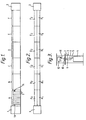
- the 144 position machine has a gearing end casing 1 at the left hand end and an off-end casing 2 at the right hand end, with six separate bays A, B, C, D, E, and F each including twenty-four separate spinning positions (twelve on each side) one of which positions is shown in more detail in Figure 3.
- the typical spinning position 3 includes a sliver can 4 from which sliver 5 is withdrawn as it is entrained into the fibre-opening unit 6 including a beater roll (not shown).
- the sliver From the fibre-opening unit the sliver, separated into individual airborne fibres, is pneumatically entrained into a spinning chamber 7 and is spun to form a yarn 8 leaving the chamber 7 by way of the conventional doffing tube 9.
- the spun yarn then passes over delivery rollers 10 to enter the traverse fan in which the yarn is caused to traverse laterally by engagement with a traverse guide 11 as it is wound onto a package 12, in this case a conical build-up on a conical winding tube serving as package former.
- the open-end spinning unit shown in Figure 3 may be a rotor spinner or a friction spinner, and equally the present invention can be applied to any multi-position machine in which winding-up of yarn onto individual packages takes place.
- the various machine bays A...F include front sets of positions A1...F1 all back-to-back with other sets of positions A2...F2.
- this machine having six bays with twelve positions on each side of each bay, there is a total of 144 positions divided up into six bays of twenty-four.
- the traverse guides of the sets of positions A1, A2, B1, B2, C1 and C2, i.e. of the three bays A, B and C at one end of the machine may all be moving towards the gearing end 1 while the traverse guides of the remaining positions D1, D2, E1, E2, F1 and F2 are all moving away from the gearing casing 1.
- This condition is illustrated diagrammatically in Figure 4A.
- Another possibility is for the. traverse guides of the sets of positions A1, A2, C1, C2, E1 and E2, i.e. of bays A, C, and E, to be moving in one direction while the traverse guides of the remaining sets of positions B1, B2, D1, D2, F1 and F2 are moving in the opposite direction.
- This condition is illustrated diagrammatically in Figure 4B.
- each of the positions has its own traverse actuator, will be for each alternate position along a bay, such as bay A, to have the same direction of traverse while the intervening positions have the opposite direction. This condition is illustrated diagrammatically in Figure 4D.
- each pair of positions which are back-to-back for example the two open-end spinning units which are directly adjacent the gearing end casing 1 in the bay A
- to have the same direction of traverse i.e. either towards or away from the gearing casing 1.
- Figure 4E shows a further embodiment which is particularly advantageous in that the phase angles differ by much smaller increments.
- the phase angle in this further embodiment is arranged such that there are many pairs of phase-linked traverse guides which are directly in opposition to one another.
- This situation is represented by a first pair of points X, X' and a second pair of points Y, Y' on the graph of Figure 4E.
- these points denote position numbers 24 and 60, and 30 and 66, along one side of the machine.
- pair X, X' these two positions are directly opposed to one another and the same two positions on the opposite side of the machine (where the number is always measured from the gearing end 1 of the machine) may have exactly the same two 180 ° opposed phase angles.
- the traverse motion phase angle differs from one position to the next by an increment of 5 ° (in order to cover the full range with uniform increments over 72 spinning stations per side of the machine).
Landscapes
- Engineering & Computer Science (AREA)
- Mechanical Engineering (AREA)
- Textile Engineering (AREA)
- Spinning Or Twisting Of Yarns (AREA)
- Winding Filamentary Materials (AREA)
- Spinning Methods And Devices For Manufacturing Artificial Fibers (AREA)
- Yarns And Mechanical Finishing Of Yarns Or Ropes (AREA)
- Looms (AREA)
- Replacing, Conveying, And Pick-Finding For Filamentary Materials (AREA)
- Preparation Of Compounds By Using Micro-Organisms (AREA)
- Micro-Organisms Or Cultivation Processes Thereof (AREA)
Claims (8)
Priority Applications (1)
| Application Number | Priority Date | Filing Date | Title |
|---|---|---|---|
| AT86307523T ATE50295T1 (de) | 1986-06-20 | 1986-10-01 | Garnspinn- und/oder -spulvorrichtung mit einer vielzahl von arbeitsstellen. |
Applications Claiming Priority (2)
| Application Number | Priority Date | Filing Date | Title |
|---|---|---|---|
| GB8615090 | 1986-06-20 | ||
| GB8615090A GB2191789B (en) | 1986-06-20 | 1986-06-20 | Multi-position yarn spinning/winding machine |
Publications (2)
| Publication Number | Publication Date |
|---|---|
| EP0249664A1 EP0249664A1 (de) | 1987-12-23 |
| EP0249664B1 true EP0249664B1 (de) | 1990-02-07 |
Family
ID=10599808
Family Applications (1)
| Application Number | Title | Priority Date | Filing Date |
|---|---|---|---|
| EP86307523A Expired - Lifetime EP0249664B1 (de) | 1986-06-20 | 1986-10-01 | Garnspinn- und/oder -spulvorrichtung mit einer Vielzahl von Arbeitsstellen |
Country Status (10)
| Country | Link |
|---|---|
| US (1) | US4696436A (de) |
| EP (1) | EP0249664B1 (de) |
| JP (1) | JPS631677A (de) |
| KR (1) | KR910000433B1 (de) |
| CN (1) | CN86107187A (de) |
| AT (1) | ATE50295T1 (de) |
| BR (1) | BR8605032A (de) |
| DE (1) | DE3668920D1 (de) |
| ES (1) | ES2013714B3 (de) |
| GB (1) | GB2191789B (de) |
Families Citing this family (6)
| Publication number | Priority date | Publication date | Assignee | Title |
|---|---|---|---|---|
| DE3806139A1 (de) * | 1988-02-26 | 1989-09-07 | Schlafhorst & Co W | Textilmaschine mit mehreren spulstellen |
| US5248089A (en) * | 1988-08-15 | 1993-09-28 | Wagner Spray Tech Corporation | Combination carrying case/paint container |
| CA1330204C (en) * | 1988-10-21 | 1994-06-14 | Peter L. Frank | Self-contained power painting system |
| CN102874652B (zh) * | 2011-07-14 | 2014-04-16 | 际华三五四二纺织有限公司 | 高效短流程嵌入式复合纺纱倒丝装置 |
| JP6781011B2 (ja) * | 2016-11-01 | 2020-11-04 | Tmtマシナリー株式会社 | トラバース装置及び糸巻取装置 |
| US12553165B2 (en) * | 2023-12-29 | 2026-02-17 | Adidas Ag | Rotational winding apparatus and method |
Family Cites Families (12)
| Publication number | Priority date | Publication date | Assignee | Title |
|---|---|---|---|---|
| US2301712A (en) * | 1939-04-06 | 1942-11-10 | Warren A Seem | Yarn winding machine |
| US2301699A (en) * | 1941-09-29 | 1942-11-10 | Whitin Machine Works | Traverse motion |
| US2400324A (en) * | 1944-01-11 | 1946-05-14 | Farrel Birmingham Co Inc | Strand packaging apparatus |
| NL78988C (de) * | 1949-04-05 | |||
| GB663802A (en) * | 1949-07-18 | 1951-12-27 | Arundel Coulthard & Co Ltd | Improvements relating to yarn winding machines |
| US2889577A (en) * | 1956-06-27 | 1959-06-09 | Nat Plastics Products Company | Spooling |
| US3018974A (en) * | 1959-03-05 | 1962-01-30 | Klinger Mfg Co Ltd | Multiple bobbin winding apparatus for yarn and the like |
| US3235192A (en) * | 1963-06-25 | 1966-02-15 | Scragg & Sons | Textile yarn winding structure |
| DE1435356A1 (de) * | 1963-12-24 | 1968-11-14 | Barmag Barmer Maschf | Spulenspinnmaschine fuer endlose nach dem Schmelz- oder Trockenspinnverfahren hergestellte kuenstliche Faeden |
| US3642217A (en) * | 1969-12-30 | 1972-02-15 | Celanese Corp | Tandem yarn winding |
| US4062503A (en) * | 1976-08-30 | 1977-12-13 | Haskell Electronics & Tool Corporation | Level winding apparatus |
| US4157793A (en) * | 1977-08-03 | 1979-06-12 | Independent Machine Company | Bobbin winding system |
-
1986
- 1986-06-20 GB GB8615090A patent/GB2191789B/en not_active Expired
- 1986-10-01 DE DE8686307523T patent/DE3668920D1/de not_active Revoked
- 1986-10-01 AT AT86307523T patent/ATE50295T1/de active
- 1986-10-01 ES ES86307523T patent/ES2013714B3/es not_active Expired - Lifetime
- 1986-10-01 EP EP86307523A patent/EP0249664B1/de not_active Expired - Lifetime
- 1986-10-15 BR BR8605032A patent/BR8605032A/pt not_active IP Right Cessation
- 1986-10-16 JP JP61246455A patent/JPS631677A/ja active Pending
- 1986-10-16 US US06/920,101 patent/US4696436A/en not_active Expired - Fee Related
- 1986-10-17 KR KR1019860008792A patent/KR910000433B1/ko not_active Expired
- 1986-10-17 CN CN198686107187A patent/CN86107187A/zh active Pending
Also Published As
| Publication number | Publication date |
|---|---|
| US4696436A (en) | 1987-09-29 |
| CN86107187A (zh) | 1987-12-30 |
| GB2191789B (en) | 1989-12-06 |
| ES2013714B3 (es) | 1990-06-01 |
| DE3668920D1 (de) | 1990-03-15 |
| GB8615090D0 (en) | 1986-07-23 |
| JPS631677A (ja) | 1988-01-06 |
| KR910000433B1 (ko) | 1991-01-25 |
| EP0249664A1 (de) | 1987-12-23 |
| BR8605032A (pt) | 1988-02-09 |
| ATE50295T1 (de) | 1990-02-15 |
| GB2191789A (en) | 1987-12-23 |
| KR880000321A (ko) | 1988-03-24 |
Similar Documents
| Publication | Publication Date | Title |
|---|---|---|
| EP0249664B1 (de) | Garnspinn- und/oder -spulvorrichtung mit einer Vielzahl von Arbeitsstellen | |
| RU2010764C1 (ru) | Устройство для крестовой намотки натуральных или синтетических нитей, подаваемых с большой скоростью | |
| EP1342686B1 (de) | Fadenführungseinrichtung für Offenend-Spinnmaschinen | |
| US3041663A (en) | Method and apparatus for forming fibers | |
| GB2060723A (en) | Winding of yarns from open- end spinners onto common former | |
| JPH03119131A (ja) | 繊維加工機械 | |
| US7225605B2 (en) | Modular air spinning frame | |
| EP1338687B1 (de) | Verfahren und Vorrichtung zur Herstellung eines Mehrfachkomponenten Effektgarnes | |
| US3279711A (en) | Winding apparatus for melt-spun or dry-spun filaments | |
| JPH08504728A (ja) | 糸巻成機 | |
| US5163280A (en) | Apparatus for synchronously driving plural spinning elements in a textile spinning machine | |
| US4462558A (en) | Yarn package and method and apparatus for producing the same | |
| US5803383A (en) | Method for avoiding constant pattern windings in winding yarn packages | |
| JP2022189000A (ja) | 紡糸引取装置 | |
| US5566905A (en) | Apparatus for winding a plurality of yarns | |
| US4436123A (en) | Device for storing filamentary material for use on a loom | |
| JPS60167855A (ja) | 綾振ドラム | |
| JP3211779B2 (ja) | 糸条綾振り装置 | |
| JP2842546B2 (ja) | ペッグトレイ搬送装置 | |
| JP2513200B2 (ja) | 精紡機等における空ボビン位置決め方法 | |
| SU1643389A1 (ru) | Машина дл перемотки нитей с бобин в мотки-либиты дл изготовлени авровых тканей | |
| JP2001316932A (ja) | 人造繊維の巻き取り方法 | |
| JPS56136760A (en) | Yarn winding method | |
| JPH0313347B2 (de) | ||
| JP3305902B2 (ja) | 粗糸落下防止機構を備える精紡機用クリール |
Legal Events
| Date | Code | Title | Description |
|---|---|---|---|
| PUAI | Public reference made under article 153(3) epc to a published international application that has entered the european phase |
Free format text: ORIGINAL CODE: 0009012 |
|
| AK | Designated contracting states |
Kind code of ref document: A1 Designated state(s): AT CH DE ES FR IT LI |
|
| 17P | Request for examination filed |
Effective date: 19880105 |
|
| 17Q | First examination report despatched |
Effective date: 19890223 |
|
| GRAA | (expected) grant |
Free format text: ORIGINAL CODE: 0009210 |
|
| AK | Designated contracting states |
Kind code of ref document: B1 Designated state(s): AT CH DE ES FR IT LI |
|
| REF | Corresponds to: |
Ref document number: 50295 Country of ref document: AT Date of ref document: 19900215 Kind code of ref document: T |
|
| ITF | It: translation for a ep patent filed | ||
| REF | Corresponds to: |
Ref document number: 3668920 Country of ref document: DE Date of ref document: 19900315 |
|
| ET | Fr: translation filed | ||
| PLBI | Opposition filed |
Free format text: ORIGINAL CODE: 0009260 |
|
| 26 | Opposition filed |
Opponent name: SCHUBERT & SALZER MASCHINENFABRIK AG Effective date: 19901107 |
|
| PGFP | Annual fee paid to national office [announced via postgrant information from national office to epo] |
Ref country code: FR Payment date: 19910911 Year of fee payment: 6 |
|
| PGFP | Annual fee paid to national office [announced via postgrant information from national office to epo] |
Ref country code: AT Payment date: 19910912 Year of fee payment: 6 |
|
| PGFP | Annual fee paid to national office [announced via postgrant information from national office to epo] |
Ref country code: CH Payment date: 19910917 Year of fee payment: 6 |
|
| PGFP | Annual fee paid to national office [announced via postgrant information from national office to epo] |
Ref country code: DE Payment date: 19910930 Year of fee payment: 6 |
|
| PGFP | Annual fee paid to national office [announced via postgrant information from national office to epo] |
Ref country code: ES Payment date: 19911014 Year of fee payment: 6 |
|
| ITTA | It: last paid annual fee | ||
| RDAG | Patent revoked |
Free format text: ORIGINAL CODE: 0009271 |
|
| STAA | Information on the status of an ep patent application or granted ep patent |
Free format text: STATUS: PATENT REVOKED |
|
| 27W | Patent revoked |
Effective date: 19920807 |
|
| REG | Reference to a national code |
Ref country code: CH Ref legal event code: PL |