EP0249562A1 - Verfahren und Anlage zur Enthaubung und Entladung einer Palette - Google Patents
Verfahren und Anlage zur Enthaubung und Entladung einer Palette Download PDFInfo
- Publication number
- EP0249562A1 EP0249562A1 EP87401330A EP87401330A EP0249562A1 EP 0249562 A1 EP0249562 A1 EP 0249562A1 EP 87401330 A EP87401330 A EP 87401330A EP 87401330 A EP87401330 A EP 87401330A EP 0249562 A1 EP0249562 A1 EP 0249562A1
- Authority
- EP
- European Patent Office
- Prior art keywords
- cutting
- cover
- layers
- installation according
- carriage
- Prior art date
- Legal status (The legal status is an assumption and is not a legal conclusion. Google has not performed a legal analysis and makes no representation as to the accuracy of the status listed.)
- Granted
Links
- 238000000034 method Methods 0.000 title claims abstract description 8
- 238000009434 installation Methods 0.000 claims description 20
- 125000006850 spacer group Chemical group 0.000 description 5
- 239000002985 plastic film Substances 0.000 description 2
- 229920006255 plastic film Polymers 0.000 description 2
- 238000010586 diagram Methods 0.000 description 1
- 238000007599 discharging Methods 0.000 description 1
- 239000000428 dust Substances 0.000 description 1
- 230000000694 effects Effects 0.000 description 1
- 238000011084 recovery Methods 0.000 description 1
- 239000002023 wood Substances 0.000 description 1
Images


Classifications
-
- B—PERFORMING OPERATIONS; TRANSPORTING
- B65—CONVEYING; PACKING; STORING; HANDLING THIN OR FILAMENTARY MATERIAL
- B65G—TRANSPORT OR STORAGE DEVICES, e.g. CONVEYORS FOR LOADING OR TIPPING, SHOP CONVEYOR SYSTEMS OR PNEUMATIC TUBE CONVEYORS
- B65G59/00—De-stacking of articles
-
- B—PERFORMING OPERATIONS; TRANSPORTING
- B65—CONVEYING; PACKING; STORING; HANDLING THIN OR FILAMENTARY MATERIAL
- B65B—MACHINES, APPARATUS OR DEVICES FOR, OR METHODS OF, PACKAGING ARTICLES OR MATERIALS; UNPACKING
- B65B69/00—Unpacking of articles or materials, not otherwise provided for
- B65B69/0033—Unpacking of articles or materials, not otherwise provided for by cutting
Definitions
- the present invention relates to the removal of pallets consisting of packages held in compact configuration by a cover, and relates to a method and an installation for removing and unloading pallets.
- the invention applies in particular, but not exclusively, to the removal of pallets of empty bottles arriving at a bottler from a glassworks.
- pallets also called “pallets” for abuse of language, from the name of the supports on which these pallets are generally made, have a structure which is not very stable as is the custom, to avoid the disintegration of these pallets during phases transport, to enclose them in a cover generally made of a shrinkable plastic film.
- This cover gives these pallets a satisfactory cohesion for transport by truck or wagon.
- it has the advantage of ensuring a tight protection, vis-à-vis rain or dust, which allows delivery in optimal conditions.
- the invention aims to make this removal operation automatic, while allowing safer and more reliable unloading of the pallets by nesting the phases of removal and depalletization.
- the invention thus proposes a method of removing and depalletizing pallets, formed by superimposed layers of adjacent packages and confined in a retaining cover, according to which the cover is cut according to superimposed horizontal planes separating the layers of package so as to leave subsist belts of cover now laterally these layers, one discharges one by one these layers, and one cuts vertically then one evacuates these side belts of cover.
- the side cover belts are cut in at least two places around its circumference, so as to avoid that, during the evacuation, by suction, preferably of the belt sections, this evacuation can induce friction likely to cause drop some packages.
- the invention proposes an installation for removing and unloading (or depalletizing) pallets, composed of superimposed layers of adjacent packages, and confined in a holding cover, comprising: a device for horizontal cutting of covers, suitable for cutting covers according to horizontal planes separating the layers of the package, so as to leave cover belts holding these layers laterally, a handling device suitable for discharging the pallets layer by layer, and - a cover cutting and evacuation device comprising at least one cutting tool for cutting the cover belts one by one and evacuation means for evacuating the latter.
- the horizontal cutting device comprises at least one horizontal cutting tool and means for driving this tool relative to and around the pallet, vertically and in horizontal planes.
- This tool is preferably carried at the end of an arm linked to a carriage movable vertically along a mast under the action of an appropriate control member.
- this arm advantageously carries two vertically offset cutting tools.
- the arm carrying the cutting tool is directly articulated about a vertical axis, on the vertically movable carriage, a rotary table is provided to support each pallet and the means of relative drive comprise means for controlling the rotation of the rotary table and an application member, such as a jack, for applying the cutting tool against the cover under a substantially predetermined pressure, or bringing it back.
- the vertically movable carriage comprises a horizontal guide frame adapted to surround the pallet with play
- the tool-carrying arm is articulated on an intermediate carriage sliding on this frame
- the means of relative drive comprising means for controlling the sliding of the intermediate carriage on the frame and an application member, such as a jack, for applying the cutting tool against the cover under a substantially predetermined pressure or bringing it back
- the intermediate carriage is advantageously linked to a chain sliding on the frame and driven in movement by a motor carried by the vertically movable carriage.
- the cutting tool is a disc, rotating around a vertical axis, provided with radially projecting knives advantageously articulated and retractable.
- the device for handling layers of packages comprises in a known manner a bell adapted to cover each layer of packages and connected to a source of suction, as shown for example by the French application for patent 85.02957.
- the cover cutting and evacuation device comprises at least one vertical cutting tool and at least one member for evacuating cover belts.
- the cutting and evacuation device comprises a plurality of at least two vertical cutting tools distributed around the layer of packages alternating with evacuation outlets in equal number connected to a suction source.
- the cutting tools, two in number are arranged on either side of a layer circulation path, and these discharge outlets, two in number, are carried by a vertically movable frame.
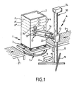
- FIGS. 1 and 3 An installation for removing the cover and depalletizing according to the invention is shown by way of example in FIGS. 1 and 3 which illustrate successive stages of removing and depalletizing a pallet 1 covered with a cover 2, generally consisting of a shrinkable plastic film, and preferably supported by a pallet 3 facilitating the handling and loading of the pallet by any suitable means such as a forklift.
- the cover 2 is first cut, in a first station comprising a horizontal cutting device as described in FIGS. 1 and 2 under the references A or A ⁇ , according to superimposed horizontal planes P, P ⁇ , P ⁇ ... separating layers 4 of package (not shown), so as to leave belts 5 of the cover holding these layers laterally.
- These layers are then discharged one by one, by any suitable means such as a device B shown in FIG. 3, of the type described in patent 85.02057 for example.
- the device C of FIG. 3 the belts 5 of the successive layers are cut and these belts cut into one or more sections are removed.
- the pallets 1 are brought to a conveyor 6 of any known suitable type (with rollers, belts, wood or rubber, chain, etc.) then introduced, in known manner, onto a rotary table 7 driven in rotation around a vertical axis under the control of a control device shown diagrammatically at 8, and connected to the latter by a connecting line shown diagrammatically at 9.
- a cutting gantry 10 comprising a vertical mast 11 held on the ground by a base 12, along which a carriage 13 moves vertically, under the action of a control motor 14, acting for example via a chain (not shown) and controlled by said control device 8 by a connecting line 15.
- an arm 16 carrying at its free end a double cutting tool 17, here consisting of two rotary knives 18 vertically offset and rotated by a motor 19.
- the arm 16 is subjected to the action of an applicator member, here consisting of a jack 20 both articulated to the carriage 13 and to the arm 16, intended to apply the double cutting tool 17 against the cover 2 covering the pallet 1 with a substantially constant pressure sufficient to allow the tool 17 to follow the contours of the pallet.
- This jack 20 is controlled by a control member, for example also controlled by the device 8 (not shown) adapted to control the retraction thereof when the pallet is introduced on the table 7 as well as for the changes of cutting plane. .
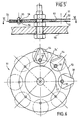
- a rotary knife 18 is shown on a large scale in FIG. 4. It comprises two discs 18A secured to a shaft 18B and between which are knife blades 18C projecting radially.
- FIGS 5 and 6 show an alternative embodiment of the cutting tool 18 of Figure 4 designated by the reference 51.
- This tool includes, like that of Figure 4, two transverse flanges 52 and 53, between which are angularly distributed knife blades 54. The latter can rotate freely around tubular spacers 55, being separated from the flanges 52 and 53 by sliding washers 56.
- a spacer disc 57 forms a spacer between the flanges.
- the knife blades 54 are cut from small discs mounted eccentrically around the spacers 55.
- a guide disc 8 of diameter substantially equal to that of the flanges, intended to follow the outline of a package to be removed.
- the cutting tool can also be constituted, for example, by a laser, a flame, a stationary knife and other known suitable tools.
- the vertical positions of the carriage 13 along the mast 11 are preprogrammed in the control device 8: we work blind.
- sensors are provided to detect the vertical position of the top of the pallet and / or the spacers separating the layers.
- the horizontal cutting device A cuts the cover 2 from top to bottom.
- the number of tools cutting vertically offset and suitable for working simultaneously of course defines the total number of cutting cycles (each cycle corresponding to a vertical position of the carriage 13).
- the pallet is removed, in known manner, on an intermediate conveyor 21, for example similar to the conveyor 6.
- control device shown diagrammatically at 8 controls the relative drive of the cutting tool with respect to the pallet.
- the horizontal cutting device A ⁇ is limited to a gantry located next to a conveyor 6 ⁇ .
- This device comprises, as in the case of FIG. 1, a mast 11 ⁇ stabilized on the ground by a base 12 ⁇ , on which a carriage 13 ⁇ moves vertically, under the action of a control motor 14 ⁇ , for example controlled by a device control diagram shown in 8 ⁇ .
- the carriage 13 ⁇ here carries a frame 22 adapted to surround with play the pallet 1, on which can slide an intermediate carriage shown diagrammatically at 23, driven along this frame by a chain 24, cooperating with a motor 25, carried by the carriage 13 ⁇ and for example controlled by the device 8 ⁇ .
- the intermediate carriage 23 carries, similarly to the carriage 13 of FIG. 1, an arm 26 carrying at one end a cutting tool 27, here a rotary knife 18 of the type shown in FIG. 4, driven by a motor 28.
- a applicator member (not shown for the sake of readability of the drawing), for example analogous to the jack 20 of FIG. 1, allows the knife 18 to be withdrawn from the pallet 1 or, on the contrary, its application under pressure against the cover 2.
- the pallet is brought by the intermediate conveyor 21 under a device B for handling layers of packages.
- This device is for example of the type described in the aforementioned patent. It comprises a vertical mast 30, movable horizontally on a frame 30A, on which moves, under the action of a motor 31, a carriage 32 provided with an arm 33 carrying a bell 34 covering one by one the layers 4 of the package. The interior of this bell is connected to a continuous suction source (not shown).
- This device B successively deposits the package layers on an evacuation conveyor 40 while the pallets 3 are evacuated, when they are empty, by any appropriate means.
- the individual layers of packages are brought successively to the device C for cutting and evacuation.
- This device comprises, around the normal position of a layer, two vertical cutting tools 41 arranged on the sides of the conveyor 40, alternating with two discharge outlets 42 connected by flexible pipes 43 to a cover recovery tank 44 fitted with a suction source.
- the cutting tools 41 here comprise a cutting finger 45 of any suitable type, for example of the laser, flame type ... carried by a slide movable vertically on slides 46 under the action of a control member 47 here consisting of a jack whose cylinder is integral with the slides.
- This control member is controlled by a control device (not shown) of any known type.
- discharge outlets 42 which are placed on either side of the layers 4 of the package in their direction of movement, they are carried by a frame or structure 48 movable in vertical translation over an amplitude at least equal to the height of the layers, under the action of a member 49 for translational control carried by a fixed gantry 50.
- the cutting fingers which are carried by a frame movable in vertical translation while the discharge outlets are arranged on either side of the conveyor 40.
Landscapes
- Engineering & Computer Science (AREA)
- Mechanical Engineering (AREA)
- De-Stacking Of Articles (AREA)
- Load-Engaging Elements For Cranes (AREA)
- Warehouses Or Storage Devices (AREA)
- Stacking Of Articles And Auxiliary Devices (AREA)
Priority Applications (1)
| Application Number | Priority Date | Filing Date | Title |
|---|---|---|---|
| AT87401330T ATE48398T1 (de) | 1986-06-13 | 1987-06-12 | Verfahren und anlage zur enthaubung und entladung einer palette. |
Applications Claiming Priority (2)
| Application Number | Priority Date | Filing Date | Title |
|---|---|---|---|
| FR8608564 | 1986-06-13 | ||
| FR8608564A FR2600040B1 (fr) | 1986-06-13 | 1986-06-13 | Procede et installation de dehoussage et de dechargement d'une paletee. |
Publications (2)
| Publication Number | Publication Date |
|---|---|
| EP0249562A1 true EP0249562A1 (de) | 1987-12-16 |
| EP0249562B1 EP0249562B1 (de) | 1989-12-06 |
Family
ID=9336300
Family Applications (1)
| Application Number | Title | Priority Date | Filing Date |
|---|---|---|---|
| EP87401330A Expired EP0249562B1 (de) | 1986-06-13 | 1987-06-12 | Verfahren und Anlage zur Enthaubung und Entladung einer Palette |
Country Status (4)
| Country | Link |
|---|---|
| EP (1) | EP0249562B1 (de) |
| AT (1) | ATE48398T1 (de) |
| DE (1) | DE3761081D1 (de) |
| FR (1) | FR2600040B1 (de) |
Cited By (12)
| Publication number | Priority date | Publication date | Assignee | Title |
|---|---|---|---|---|
| WO1993011043A1 (en) * | 1991-12-06 | 1993-06-10 | Renato Prescendo | Equipment for the automatic cutting of the wrapping film and subsequent depalletization of empty plastic or glass bottles or phials prior to their filling |
| EP0569643A1 (de) * | 1992-05-14 | 1993-11-18 | Oji Seitai Kaisha, Ltd. | Auswickelvorrichtung mit Schwenkarmen und Greifern |
| EP0583742A1 (de) * | 1992-08-18 | 1994-02-23 | Körber Ag | Verfahren und Vorrichtung zum Entfernen der Juteumhüllung von einem Tabakballen |
| EP0587051A1 (de) * | 1992-09-03 | 1994-03-16 | Kao Corporation | Verfahren und Vorrichtung zur Trennung und Rekuperation von Umreifungen |
| ITFR20090002A1 (it) * | 2009-02-16 | 2009-05-16 | Danilo Gabriele | Sistema apertura facilitata fardelli |
| ES2325295A1 (es) * | 2008-02-29 | 2009-08-31 | Envasados Eva, S.A. | Maquina para desenvolver palets. |
| WO2010087720A1 (en) * | 2009-01-30 | 2010-08-05 | Stavanger Engineering As | Apparatus and method for cutting of packaged bales |
| ITMO20090272A1 (it) * | 2009-11-12 | 2011-05-13 | Bortolin Kemo Spa | Macchina per la depallettizzazione di un carico multistrato. |
| WO2012054676A1 (en) * | 2010-10-20 | 2012-04-26 | Siemens Industry, Inc. | Film-wrapped bundle opener |
| EP2466558A3 (de) * | 2010-11-05 | 2014-02-12 | Bistrobox GmbH | Enpackungsvorrichtung |
| EP3214004A1 (de) | 2016-03-03 | 2017-09-06 | Freixenet, S.A. | Verfahren zum auspacken einer palettisierten ladung und vorrichtung zur durchführung des verfahrens |
| IT201700076014A1 (it) * | 2017-07-06 | 2019-01-06 | Simac Tech S R L | Apparecchiatura per la rimozione di film protettivi |
Citations (1)
| Publication number | Priority date | Publication date | Assignee | Title |
|---|---|---|---|---|
| EP0142846A1 (de) * | 1983-11-21 | 1985-05-29 | LEONARDO S.r.l. | Maschine zum automatischen Entfernen der Kunststoffhüllen von palettierten Lasten |
-
1986
- 1986-06-13 FR FR8608564A patent/FR2600040B1/fr not_active Expired
-
1987
- 1987-06-12 AT AT87401330T patent/ATE48398T1/de not_active IP Right Cessation
- 1987-06-12 DE DE8787401330T patent/DE3761081D1/de not_active Expired - Lifetime
- 1987-06-12 EP EP87401330A patent/EP0249562B1/de not_active Expired
Patent Citations (1)
| Publication number | Priority date | Publication date | Assignee | Title |
|---|---|---|---|---|
| EP0142846A1 (de) * | 1983-11-21 | 1985-05-29 | LEONARDO S.r.l. | Maschine zum automatischen Entfernen der Kunststoffhüllen von palettierten Lasten |
Cited By (20)
| Publication number | Priority date | Publication date | Assignee | Title |
|---|---|---|---|---|
| WO1993011043A1 (en) * | 1991-12-06 | 1993-06-10 | Renato Prescendo | Equipment for the automatic cutting of the wrapping film and subsequent depalletization of empty plastic or glass bottles or phials prior to their filling |
| EP0569643A1 (de) * | 1992-05-14 | 1993-11-18 | Oji Seitai Kaisha, Ltd. | Auswickelvorrichtung mit Schwenkarmen und Greifern |
| EP0583742A1 (de) * | 1992-08-18 | 1994-02-23 | Körber Ag | Verfahren und Vorrichtung zum Entfernen der Juteumhüllung von einem Tabakballen |
| EP0587051A1 (de) * | 1992-09-03 | 1994-03-16 | Kao Corporation | Verfahren und Vorrichtung zur Trennung und Rekuperation von Umreifungen |
| US5425219A (en) * | 1992-09-03 | 1995-06-20 | Kao Corporation | Method and apparatus for cutting and recovering bundling body |
| ES2325295A1 (es) * | 2008-02-29 | 2009-08-31 | Envasados Eva, S.A. | Maquina para desenvolver palets. |
| WO2009106655A1 (es) * | 2008-02-29 | 2009-09-03 | Establecimientos Eva, S.A. | Maquina para desenvolver palets |
| ES2325295B1 (es) * | 2008-02-29 | 2010-04-20 | Establecimientos Eva S.A. | Maquina para desenvolver palets. |
| WO2010087720A1 (en) * | 2009-01-30 | 2010-08-05 | Stavanger Engineering As | Apparatus and method for cutting of packaged bales |
| ITFR20090002A1 (it) * | 2009-02-16 | 2009-05-16 | Danilo Gabriele | Sistema apertura facilitata fardelli |
| ITMO20090272A1 (it) * | 2009-11-12 | 2011-05-13 | Bortolin Kemo Spa | Macchina per la depallettizzazione di un carico multistrato. |
| WO2011058456A1 (en) * | 2009-11-12 | 2011-05-19 | Bortolin Kemo S.P.A. | A machine for depalletising a multi-layer load |
| WO2012054676A1 (en) * | 2010-10-20 | 2012-04-26 | Siemens Industry, Inc. | Film-wrapped bundle opener |
| US9637263B2 (en) | 2010-10-20 | 2017-05-02 | Siemens Industry, Inc. | Film-wrapped bundle opener |
| EP2466558A3 (de) * | 2010-11-05 | 2014-02-12 | Bistrobox GmbH | Enpackungsvorrichtung |
| EP3214004A1 (de) | 2016-03-03 | 2017-09-06 | Freixenet, S.A. | Verfahren zum auspacken einer palettisierten ladung und vorrichtung zur durchführung des verfahrens |
| US10889400B2 (en) * | 2016-03-03 | 2021-01-12 | Freixenet, S.A. | Method of unwrapping a palletized load and device for carrying out said method |
| AU2017225227B2 (en) * | 2016-03-03 | 2022-01-06 | Freixenet, S.A. | Method of unwrapping a palletised load and device for carrying out said method |
| IT201700076014A1 (it) * | 2017-07-06 | 2019-01-06 | Simac Tech S R L | Apparecchiatura per la rimozione di film protettivi |
| WO2019008535A1 (en) * | 2017-07-06 | 2019-01-10 | Simac Tech S.R.L. | APPARATUS FOR REMOVAL OF PROTECTIVE FILMS |
Also Published As
| Publication number | Publication date |
|---|---|
| FR2600040A1 (fr) | 1987-12-18 |
| DE3761081D1 (de) | 1990-01-11 |
| FR2600040B1 (fr) | 1988-10-21 |
| EP0249562B1 (de) | 1989-12-06 |
| ATE48398T1 (de) | 1989-12-15 |
Similar Documents
| Publication | Publication Date | Title |
|---|---|---|
| EP0510159B1 (de) | Verfahren, maschine und einrichtung zum verpacken einer mit einem kantenschutzstreifen versehenen ladung, vorrichtung zum ergreifen, fördern, ablegen und halten eines dergleichen streifens | |
| EP0533520B1 (de) | Verfahren und Vorrichtung zum Verpacken von palletierten Ladungen | |
| EP0411981B1 (de) | Verfahren und Maschine zum Banderolieren einer palettisierten Ladung | |
| EP0354873B1 (de) | Entpalettierer für Etikettenbündel | |
| EP0249562B1 (de) | Verfahren und Anlage zur Enthaubung und Entladung einer Palette | |
| FR2679818A1 (fr) | Procede et dispositif pour la decoupe de plaques de verre plat. | |
| CH703288B1 (fr) | Procédé et dispositif de chargement automatique de pièces plates dans un dispositif d'alimentation de machines traitant de pièces plates, notamment des enveloppes. | |
| FR2742123A1 (fr) | Machine destinee a liberer une balle, notamment une balle de tabac, a partir d'un emballage | |
| EP0645309B1 (de) | Verfahren und Vorrichtung zur Anpassung der Höhe einer Verpackung an die Höhe ihres Inhalts und Schneidevorrichtung dafür | |
| FR2550057A1 (fr) | Dispositif pour fabriquer des blocs de gaufre | |
| EP0188987B1 (de) | Palettiervorrichtung, insbesondere für Säcke | |
| EP0057144B1 (de) | Maschine zum Verpacken von zylinderförmigen Artikeln in kreisförmigen Zuschnitten, geformt aus Bahnen von thermoplastischem Verpackungsmaterial | |
| EP0354083B1 (de) | Verfahren und Anlage zum Behandeln und Verpacken von Gegenständen, wie leeren Behältern und auf diese Art palettisierte Ladung | |
| EP1923315B1 (de) | Verfahren zum Entfernen einer Tasche von einem brotartigen Lebensmittel | |
| EP0249534B2 (de) | Verfahren und Vorrichtung zum Verpacken einer Palettenladung in eine Hülle aus wärmeschrumpffähiger Kunststoffolie | |
| FR2702694A1 (fr) | Dispositif pour le chargement et le déchargement de machines à roder et pierrer. | |
| EP1048571A1 (de) | Vorrichtung zum umhüllen einer palettisierten Ladung mittels eines Heissschrumpfschlauches | |
| EP0059818A1 (de) | Maschine zum Anbringen von einzelnen Schutzabschnitten um längliche Gegenstände, wie z.B. Flaschen, und Aneinanderreihung solcher Maschinen | |
| EP4041539B1 (de) | Vorrichtung und verfahren zum bilden eines behälters durch falten | |
| FR2545070A1 (fr) | Machine et procede de groupage de plateaux ou analogues | |
| FR2537903A1 (fr) | Dispositif de presentation de pieces a usiner | |
| EP0152712B1 (de) | Verfahren zum Zusammensetzen einer Ladung aus horizontalen Säcken- oder Dosen-Schichten und Vorrichtung dazu | |
| CA1245239A (fr) | Procede et dispositif de prehension de colis | |
| FR2903668A1 (fr) | Machine de ficelage pour la mise en place de liens croises autour de produits, notamment de produits carnes | |
| FR2861366A1 (fr) | Dispositif d'emballage pour le remplissage de conteneurs tel que des cartons au moyen de plateaux delivres en sortie d'une chaine de conditionnement |
Legal Events
| Date | Code | Title | Description |
|---|---|---|---|
| PUAI | Public reference made under article 153(3) epc to a published international application that has entered the european phase |
Free format text: ORIGINAL CODE: 0009012 |
|
| AK | Designated contracting states |
Kind code of ref document: A1 Designated state(s): AT BE CH DE ES FR GB GR IT LI LU NL SE |
|
| 17P | Request for examination filed |
Effective date: 19880302 |
|
| 17Q | First examination report despatched |
Effective date: 19890306 |
|
| GRAA | (expected) grant |
Free format text: ORIGINAL CODE: 0009210 |
|
| AK | Designated contracting states |
Kind code of ref document: B1 Designated state(s): AT BE CH DE ES FR GB GR IT LI LU NL SE |
|
| PG25 | Lapsed in a contracting state [announced via postgrant information from national office to epo] |
Ref country code: IT Free format text: LAPSE BECAUSE OF FAILURE TO SUBMIT A TRANSLATION OF THE DESCRIPTION OR TO PAY THE FEE WITHIN THE PRE;WARNING: LAPSES OF ITALIAN PATENTS WITH EFFECTIVE DATE BEFORE 2007 MAY HAVE OCCURRED AT ANY TIME BEFORE 2007. THE CORRECT EFFECTIVE DATE MAY BE DIFFERENT FROM THE ONE RECORDED.SCRIBED TIME-LIMIT Effective date: 19891206 Ref country code: AT Effective date: 19891206 Ref country code: GR Free format text: LAPSE BECAUSE OF FAILURE TO SUBMIT A TRANSLATION OF THE DESCRIPTION OR TO PAY THE FEE WITHIN THE PRESCRIBED TIME-LIMIT Effective date: 19891206 Ref country code: GB Effective date: 19891206 Ref country code: SE Effective date: 19891206 Ref country code: NL Effective date: 19891206 |
|
| REF | Corresponds to: |
Ref document number: 48398 Country of ref document: AT Date of ref document: 19891215 Kind code of ref document: T |
|
| REF | Corresponds to: |
Ref document number: 3761081 Country of ref document: DE Date of ref document: 19900111 |
|
| PG25 | Lapsed in a contracting state [announced via postgrant information from national office to epo] |
Ref country code: ES Free format text: LAPSE BECAUSE OF FAILURE TO SUBMIT A TRANSLATION OF THE DESCRIPTION OR TO PAY THE FEE WITHIN THE PRESCRIBED TIME-LIMIT Effective date: 19900317 |
|
| NLV1 | Nl: lapsed or annulled due to failure to fulfill the requirements of art. 29p and 29m of the patents act | ||
| GBV | Gb: ep patent (uk) treated as always having been void in accordance with gb section 77(7)/1977 [no translation filed] | ||
| PG25 | Lapsed in a contracting state [announced via postgrant information from national office to epo] |
Ref country code: BE Effective date: 19900630 Ref country code: CH Effective date: 19900630 Ref country code: LU Free format text: LAPSE BECAUSE OF NON-PAYMENT OF DUE FEES Effective date: 19900630 Ref country code: LI Effective date: 19900630 |
|
| PLBE | No opposition filed within time limit |
Free format text: ORIGINAL CODE: 0009261 |
|
| STAA | Information on the status of an ep patent application or granted ep patent |
Free format text: STATUS: NO OPPOSITION FILED WITHIN TIME LIMIT |
|
| 26N | No opposition filed | ||
| BERE | Be: lapsed |
Owner name: THIBAULT JASQUES GABRIEL AUGUSTE Effective date: 19900630 |
|
| REG | Reference to a national code |
Ref country code: CH Ref legal event code: PL |
|
| PGFP | Annual fee paid to national office [announced via postgrant information from national office to epo] |
Ref country code: FR Payment date: 19940527 Year of fee payment: 8 |
|
| PGFP | Annual fee paid to national office [announced via postgrant information from national office to epo] |
Ref country code: DE Payment date: 19940617 Year of fee payment: 8 |
|
| PG25 | Lapsed in a contracting state [announced via postgrant information from national office to epo] |
Ref country code: FR Effective date: 19960229 |
|
| PG25 | Lapsed in a contracting state [announced via postgrant information from national office to epo] |
Ref country code: DE Effective date: 19960301 |
|
| REG | Reference to a national code |
Ref country code: FR Ref legal event code: ST |