EP0248560A1 - Extrudermundstück - Google Patents
Extrudermundstück Download PDFInfo
- Publication number
- EP0248560A1 EP0248560A1 EP19870304404 EP87304404A EP0248560A1 EP 0248560 A1 EP0248560 A1 EP 0248560A1 EP 19870304404 EP19870304404 EP 19870304404 EP 87304404 A EP87304404 A EP 87304404A EP 0248560 A1 EP0248560 A1 EP 0248560A1
- Authority
- EP
- European Patent Office
- Prior art keywords
- support plate
- core support
- core
- die
- members
- Prior art date
- Legal status (The legal status is an assumption and is not a legal conclusion. Google has not performed a legal analysis and makes no representation as to the accuracy of the status listed.)
- Withdrawn
Links
Images


Classifications
-
- B—PERFORMING OPERATIONS; TRANSPORTING
- B28—WORKING CEMENT, CLAY, OR STONE
- B28B—SHAPING CLAY OR OTHER CERAMIC COMPOSITIONS; SHAPING SLAG; SHAPING MIXTURES CONTAINING CEMENTITIOUS MATERIAL, e.g. PLASTER
- B28B3/00—Producing shaped articles from the material by using presses; Presses specially adapted therefor
- B28B3/20—Producing shaped articles from the material by using presses; Presses specially adapted therefor wherein the material is extruded
- B28B3/26—Extrusion dies
-
- B—PERFORMING OPERATIONS; TRANSPORTING
- B28—WORKING CEMENT, CLAY, OR STONE
- B28B—SHAPING CLAY OR OTHER CERAMIC COMPOSITIONS; SHAPING SLAG; SHAPING MIXTURES CONTAINING CEMENTITIOUS MATERIAL, e.g. PLASTER
- B28B3/00—Producing shaped articles from the material by using presses; Presses specially adapted therefor
- B28B3/20—Producing shaped articles from the material by using presses; Presses specially adapted therefor wherein the material is extruded
- B28B3/206—Forcing the material through screens or slots
-
- D—TEXTILES; PAPER
- D01—NATURAL OR MAN-MADE THREADS OR FIBRES; SPINNING
- D01D—MECHANICAL METHODS OR APPARATUS IN THE MANUFACTURE OF ARTIFICIAL FILAMENTS, THREADS, FIBRES, BRISTLES OR RIBBONS
- D01D4/00—Spinnerette packs; Cleaning thereof
- D01D4/02—Spinnerettes
Definitions
- This invention relates to an extrusion die and in particular to a form of die construction that is suitable for producing extrudates having a plurality of passages extending through the length thereof.
- dies for such extrudates have included a plurality of rigid core rods extending from a spider or die member, herein termed a core support plate, positioned upstream of the die exit with means to supply the material being extruded to the downstream side of the core support plate: such supply means commonly comprise holes, or channels, through the core support plate at locations between the core rods.
- a core support plate positioned upstream of the die exit with means to supply the material being extruded to the downstream side of the core support plate: such supply means commonly comprise holes, or channels, through the core support plate at locations between the core rods.
- an extrusion die for the production of an extrudate having a plurality of through passages of maximum cross-sectional dimension 2 mm with a spacing between the centres of adjacent passages of less than 5 mm, comprising:
- the invention also provides a process for the production of an extrudate comprising feeding an extrudable material to the inlet region of the housing of a die as aforesaid, said material being fed to said inlet region at such a rate that the material flows through said channels to the downstream side of the core support plate and thence, in plug flow fashion, out of said orifice, whereby the flow of said material causes said flexible members substantially to follow the lines of material flow and to assume a configuration at said outlet region corresponding to the desired disposition of said passages in the extrudate.
- advantage is thus taken of the streamline flow of the extrudable composition to cause the cores formed by the flexible members to adopt the relative positions appropriate to the desired spacing of the passages in the extrudate.
- each flexible member may have an enlarged portion at the end remote from the core support plate, it is preferred that the flexible members have a uniform cross section which is preferably circular, although other shapes, eg polygons such as triangles, squares, or hexagons, or re-entrant shapes eg clover leaf, may be employed if desired. Also, as mentioned hereinafter, the flexible members may be hollow, ie tubes.
- the flexibility of the flexible members and the tension created therein by the extrudable composition flowing past the flexible members will affect the disposition they adopt in the outlet region in relation to their disposition at the core support plate. Also the size of the feed channels in the core support plate, and their disposition relative to the flexible members, will also affect the disposition adopted by the flexible members at the die outlet.
- the extrusion may be effected at temperatures ranging from 10 to 100°C and in some cases the flexible members may be monofilaments of plastics material, eg nylon.
- the flexible members preferably have a substantially circular cross-section of diameter in the range 0.05 to 2, particularly 0.2 to 1.0, mm.
- the dies of the invention are of particular utility in the production of extrudates having a relatively large number of passages per unit cross section area of the extrudate.
- the number of core members is at least 20, particularly at least 25, per square cm of the orifice cross-section.
- the cross-sectional area of the inlet region of the housing is preferably 4 to 100 times the cross sectional area of the orifice.
- the core support plate is preferably constructed so that the flexible members can readily be replaced after a period of extrusion.
- the core support plate may be provided with a plurality of small holes sized to permit passage of the flexible members therethrough and the flexible members are simply passed through these holes with means, eg, in the case of flexible members in the form of monofilaments, knots or globules formed by heating the end of the flexible member, on the upstream side of the core support plate to prevent the flexible member from being pulled through its associated hole during extrusion.
- ends of a length of flexible core member material may be passed through adjacent holes in the core support plate so that a single length of core member material forms two adjacent core members, the loop of core member material between adjacent holes thus serving to prevent the core members from being pulled through the holes during extrusion.
- the invention also provides extrusion die components for use in a die as described above, comprising
- the outlet region of the housing preferably has a die land of substantially uniform cross-section: the flexible members preferably extend into such a uniform cross-sectional area die land and, in particular, at least to the downstream end of the die land.
- the die land preferably has a length of 1 to 5 times the minimum cross-sectional dimension of the orifice.
- the core support plate is preferably disposed at a distance from the orifice at least equal to one third of the minimum cross-sectional dimension of the inlet region of the housing at the location of the core support plate.
- the core support plate is preferably disposed at a distance from the orifice equal to the die land length plus one third to three times, particularly one to two times, the minimum cross-sectional dimension of the inlet region of the housing at the location of the core support plate.
- the housing has a multiplicity of inlet regions, each of which has its associated outlet region, terminating in an orifice, and core support plate provided with the feed channels and the core members.
- core support plate may be provided having an array of feed channels, and core members, for each inlet region in the housing.
- the flexible members preferably have a uniform cross section
- This enables passages of a given cross section to be made using flexible members that, for a substantial, eg major, portion of their length, have a thinner cross section and hence a greater flexibility and consequent more complete alignment with the laminar flow lines.
- Such enlargements may have a cross sectional shape dissimilar to that of the flexible members: thus the latter may be of circular cross section with enlargements of triangular, square, or hexagonal cross section.
- the flexible member has a tapered transition region between the thinner cross section portion and the enlarged portion.
- the die may be constructed with a plurality of orifices in order to provide a plurality of extrudates using a single core support plate.
- the flexible members assume a disposition approximately corresponding to the laminar flow pattern of the material undergoing extrusion, in order to obtain a uniform spacing of passages in the extrudate, it may be thought that the flexible members should be positioned at the core support plate in accordance with a square law.
- various other factors have an affect on the disposition adopted by the flexible members in the outlet region of the die.
- the core support plate configuration ie the shape and size of the feed channels and the disposition of the flexible members in relation to the feed channels, required to achieve any desired disposition of passages in the extrudate formed from any given material under given extrusion conditions may be determined by experiment. In some cases it may be desirable to modify the thickness of the core support plate across its width. For example it may have a "convex lens" configuration: such a configuration will affect the flow of material through the feed channels.
- the flexible members are positioned at the core support plate such that, under design extrusion conditions, the extrudate has passages evenly spaced with their centres at the apices of equilateral triangles.
- locating members eg spiders, through which the flexible members or enlargements thereof pass, or projections on some or all of the flexible members, especially those carrying enlargements, round which the extrudable composition can flow, may be provided to locate the passage defining members, ie the flexible members or enlargements thereon, in spatial relationship to one another.
- spatial arrangement of the passages can be determined by such locating members and the portions of the flexible members upstream of the locating members merely serve to provide the longitudinal connection for the passage defining members to the core support plate.
- the flexible members need not be arranged at the core support plate such that they follow the lines of laminar flow upstream of the locating members.
- the invention is of particular utility for the production of multiholed ceramic units eg for use as tower packings or as catalysts or catalyst supports.
- multiholed ceramic units eg for use as tower packings or as catalysts or catalyst supports.
- Examples of ceramic compositions that can be extruded using dies in accordance with the invention are described in EP-A-134138.
- the die of Figures 1 and 2 comprises a housing 10 having a flange 12 abutting a flange 14 of an extruder barrel 16: a circular core plate 18 is clamped between the barrel and housing 10.
- the housing 10 has an inlet cylindrical region 20 and a cylindrical outlet region 22 forming the die land terminating in an orifice 24.
- Intermediate the inlet and outlet regions is a frusto-conical region 26.
- This region need not be of frusto-conical configuration - thus a cylindrical section could be employed although this will give rise to a stagnant region of the extrudable material during extrusion.
- Core support plate 18 has a plurality of circular cross section feed channels 28 therethrough for the passage of extrudable material from the extruder barrel 16 and a plurality of small holes 30 through each of which a flexible core defining member 32, eg a nylon monofilament, passes.
- a flexible core defining member 32 eg a nylon monofilament
- Each core member has a stopper knot 34 upstream of the core support plate 18 to retain the core member 32.
- cores 32 arranged with one central core, a first circle of seven cores, an intermediate circle of fourteen cores, and an outer circle of twenty eight cores.
- feed channels arranged as a central channel, a first circle of seven intermediate channels, a second circle of fourteen intermediate channels, and an outer circle of fourteen channels.
- the central core member is supported by a member 44 bridging the central channel.
- the die has four orifices 24 each fed via a frusto-conical region 26 from feed channels 28 in a core support plate 18.
- the core support plate 18 is provided with a series of feed channels 28 and holes (not shown) through which the flexible members associated with the appropriate orifice pass.
- the core support plate 18 is supported as shown in Figure 2 in a recess in the housing 10 incorporating the outlet orifices 24.
- the central region 38 of the core support plate 18 is supported by the central part of housing 10.
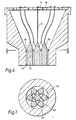
- the flexible members 32 are provided with enlarged portions 46 at their ends remote from the core support plate 18. These enlarged portions 46 extend along at least the length of the die land 22.
- the enlarged portions 46 have a hexagonal cross section thereby defining passages of hexagonal cross section in the extrudate. In the arrangement shown in Figures 6 and 7 there are seven such core members.
- the enlarged portions 46 are provided, at a point upstream of the outlet end 24 of the die, with projections 48 which engage with the interior surface of die land 22 or with the enlarged portion 46 of an adjacent flexible member 32.
- projections are shaped so that the extrudable material can flow between the projections and reunite on the downstream side thereof.
- a tapered transition section 50 to assist distribution of the extrudable material to the flow channels between the interior surface of the die land 22 and the enlarged portions 46 of the flexible members 32 or to between adjacent enlarged portions 46 of the flexible members 32.
- a spider may be provided upstream of the enlarged portions 46 and having holes therein through which the flexible members 32 pass.
- Haematite was milled to a fine powder, having a median particle size of 3 ⁇ m, all the particles having a size below 10 ⁇ m.
- the mixture was then extruded at room temperature through the fifty core die described above in relation to Figures 1 and 2 and which had an orifice of 9.5 mm diameter.
- the core members were nylon monofilaments of diameter 0.5 mm.
- the inlet region of the die at the core support plate had a diameter of 70 mm and the feed channels were of the following dimensions and disposition:
- the holes for the core support members were of 0.75 mm diameter and were disposed in circles of diameters 9.5, 22, and 35 mm.
- the cylindrical extrudates having 50 passages extending longitudinally through, were cut into lengths, dried at 30°C for 12 hours under a humidity controlled atmosphere, then heated to 400°C at a rate of 200°C per hour, and held at 400°C until the organic components were fully burnt out.
- the extruded articles were then sintered at 1300°C in an air atmosphere for 4 hours, and then cooled to ambient over 6 hours.
- the sintered extrudates which were cylinders of length 8.5 mm and diameter 8.5 mm with 50 passages of diameter about 0.48 mm extending therethrough, had a particle density, as determined by reference to their volume in mercury at atmospheric pressure, of about 4 g.cm ⁇ 3, and, after reduction of the haematite to iron, were suitable for use as ammonia synthesis catalysts.
- Example 1 The procedure of Example 1 was repeated using the haematite composition and a die of the type described in relation to Figures 1 and 2 having an orifice of hexagonal cross section with a maximum cross-section dimension of 18 mm. 200 cores of nylon monofilaments of 0.19 mm diameter were employed disposed such that, in the extrudate, the passages were approximately at the apices of equilateral triangles. The extrudate was cut into lengths of about 40 mm before drying.
- Example 1 The procedure of Example 1 was repeated using a zeolite composition in place of the haematite composition and employing a die of the type shown in Figures 1 and 2 having an orifice of 3 mm diameter and having 37 cores of nylon monofilament of diameter 0.2 mm disposed so that the passages in the extrudate were at the apices of equilateral triangles. Similar extrudates were obtained using cores of nylon monofilament of diameter 0.25 mm.
Landscapes
- Engineering & Computer Science (AREA)
- Mechanical Engineering (AREA)
- Manufacturing & Machinery (AREA)
- Chemical & Material Sciences (AREA)
- Ceramic Engineering (AREA)
- Textile Engineering (AREA)
- Extrusion Moulding Of Plastics Or The Like (AREA)
- Manufacturing Of Tubular Articles Or Embedded Moulded Articles (AREA)
- Press-Shaping Or Shaping Using Conveyers (AREA)
Applications Claiming Priority (2)
| Application Number | Priority Date | Filing Date | Title |
|---|---|---|---|
| GB8613417A GB8613417D0 (en) | 1986-06-03 | 1986-06-03 | Extrusion die |
| GB8613417 | 1986-06-03 |
Publications (1)
| Publication Number | Publication Date |
|---|---|
| EP0248560A1 true EP0248560A1 (de) | 1987-12-09 |
Family
ID=10598838
Family Applications (1)
| Application Number | Title | Priority Date | Filing Date |
|---|---|---|---|
| EP19870304404 Withdrawn EP0248560A1 (de) | 1986-06-03 | 1987-05-18 | Extrudermundstück |
Country Status (6)
| Country | Link |
|---|---|
| EP (1) | EP0248560A1 (de) |
| JP (1) | JPS62297110A (de) |
| CN (1) | CN87104060A (de) |
| AU (1) | AU7339387A (de) |
| DK (1) | DK282687A (de) |
| GB (1) | GB8613417D0 (de) |
Cited By (6)
| Publication number | Priority date | Publication date | Assignee | Title |
|---|---|---|---|---|
| AT404108B (de) * | 1994-08-09 | 1998-08-25 | Prerovske Strojirny As | Strangpressmatrize zur herstellung von pressteilen aus einem keramischen material |
| EP1481779A2 (de) | 2003-05-20 | 2004-12-01 | Ngk Insulators, Ltd. | Formmatrize und Verfahren zur Herstellung eines Formkörpers durch diese Formmatrize |
| KR100729961B1 (ko) | 2005-09-26 | 2007-06-21 | (주)에프에이대원 | 토련기의 토출마우스 |
| US20100243764A1 (en) * | 2007-07-31 | 2010-09-30 | Hokuriku Seikei Industrial Co., Ltd. | Nozzle member and process for producing the same |
| US20120006061A1 (en) * | 2010-07-08 | 2012-01-12 | Eiji Terao | Method of manufacturing glass substrate and method of manufacturing electronic components |
| DE102012223349B4 (de) * | 2011-12-21 | 2020-10-01 | Nanostone Water Gmbh | Mundstück eines Extruders zur Herstellung mindestens eines Formkörpers |
Families Citing this family (9)
| Publication number | Priority date | Publication date | Assignee | Title |
|---|---|---|---|---|
| US5989420A (en) * | 1994-12-27 | 1999-11-23 | Yuugengaisya Mikazuki Bunkakaikan | Porous ceramic filter, method of manufacturing the same, ceramic filter manufacturing extrusion molding die and extrusion molding apparatus using the die |
| CN101513673B (zh) * | 2008-02-22 | 2012-07-25 | 北京中科三环高技术股份有限公司 | 用于挤出机的一次挤出多件磁体的流道装置及用该装置的制备方法 |
| CN104260189A (zh) * | 2014-08-14 | 2015-01-07 | 滁州市南谯生辉新型建材有限公司 | 一种空心砖挤压成型模头装置 |
| CN108439982B (zh) * | 2018-05-14 | 2021-06-15 | 济南大学 | 一种轴向复合负温度系数热敏陶瓷材料及其制备方法 |
| CN110142849B (zh) * | 2019-05-20 | 2020-10-02 | 河海大学 | 一种多尺度衬砌模型轴心精确定位装置及其操作方法 |
| CN112743904B (zh) * | 2019-10-31 | 2023-02-17 | 中国石油化工股份有限公司 | 用于成型的挤条机孔板和挤条机 |
| CN110788966B (zh) * | 2019-11-29 | 2025-06-13 | 河南省众邦伟业科技有限公司 | 轻质隔墙板推挤机 |
| CN113149405B (zh) * | 2021-05-18 | 2022-12-06 | 杭州光学精密机械研究所 | 一种高效制备硫系玻璃细棒的方法 |
| CN113233745A (zh) * | 2021-05-18 | 2021-08-10 | 杭州长波红外科技有限公司 | 一种气氛保护型硫系玻璃棒挤出设备及其运行工艺 |
Citations (4)
| Publication number | Priority date | Publication date | Assignee | Title |
|---|---|---|---|---|
| DE588556C (de) * | 1930-12-13 | 1933-11-20 | Karl Korbacher | Einsatz fuer das Mundstueck von Strangpressen zum Erzeugen enggelochter Mauersteine |
| DE675280C (de) * | 1936-05-07 | 1939-05-04 | Thomas Koidl | Vorrichtung zum Herstellen von rissefreien, glatte Waende und Stege aufweisenden Hohlsteinen auf Strangpressen |
| DE1069052B (de) * | 1959-11-12 | Eisen- und Hartgußwerk "Coucordia" Gesellschaft mit beschränkter Haftung, Hameln/Weser | Vorrichtung zum Zerstören der Struktur in einer Schneckenstrangpresse für keramische Massen | |
| GB1207952A (en) * | 1966-07-06 | 1970-10-07 | Mini Of Technology | Improvements in or relating to extrusion apparatus |
-
1986
- 1986-06-03 GB GB8613417A patent/GB8613417D0/en active Pending
-
1987
- 1987-05-18 EP EP19870304404 patent/EP0248560A1/de not_active Withdrawn
- 1987-05-26 AU AU73393/87A patent/AU7339387A/en not_active Abandoned
- 1987-06-02 DK DK282687A patent/DK282687A/da not_active Application Discontinuation
- 1987-06-03 CN CN 87104060 patent/CN87104060A/zh active Pending
- 1987-06-03 JP JP13964787A patent/JPS62297110A/ja active Pending
Patent Citations (4)
| Publication number | Priority date | Publication date | Assignee | Title |
|---|---|---|---|---|
| DE1069052B (de) * | 1959-11-12 | Eisen- und Hartgußwerk "Coucordia" Gesellschaft mit beschränkter Haftung, Hameln/Weser | Vorrichtung zum Zerstören der Struktur in einer Schneckenstrangpresse für keramische Massen | |
| DE588556C (de) * | 1930-12-13 | 1933-11-20 | Karl Korbacher | Einsatz fuer das Mundstueck von Strangpressen zum Erzeugen enggelochter Mauersteine |
| DE675280C (de) * | 1936-05-07 | 1939-05-04 | Thomas Koidl | Vorrichtung zum Herstellen von rissefreien, glatte Waende und Stege aufweisenden Hohlsteinen auf Strangpressen |
| GB1207952A (en) * | 1966-07-06 | 1970-10-07 | Mini Of Technology | Improvements in or relating to extrusion apparatus |
Cited By (10)
| Publication number | Priority date | Publication date | Assignee | Title |
|---|---|---|---|---|
| AT404108B (de) * | 1994-08-09 | 1998-08-25 | Prerovske Strojirny As | Strangpressmatrize zur herstellung von pressteilen aus einem keramischen material |
| EP1481779A2 (de) | 2003-05-20 | 2004-12-01 | Ngk Insulators, Ltd. | Formmatrize und Verfahren zur Herstellung eines Formkörpers durch diese Formmatrize |
| EP1481779A3 (de) * | 2003-05-20 | 2010-07-07 | Ngk Insulators, Ltd. | Formmatrize und Verfahren zur Herstellung eines Formkörpers durch diese Formmatrize |
| US7793529B2 (en) | 2003-05-20 | 2010-09-14 | Ngk Insulators, Ltd. | Method for producing a formed body using a forming jig |
| KR100729961B1 (ko) | 2005-09-26 | 2007-06-21 | (주)에프에이대원 | 토련기의 토출마우스 |
| US20100243764A1 (en) * | 2007-07-31 | 2010-09-30 | Hokuriku Seikei Industrial Co., Ltd. | Nozzle member and process for producing the same |
| US8858864B2 (en) * | 2007-07-31 | 2014-10-14 | Tokyo Electron Limited | Nozzle member and process for producing the same |
| US20120006061A1 (en) * | 2010-07-08 | 2012-01-12 | Eiji Terao | Method of manufacturing glass substrate and method of manufacturing electronic components |
| CN102332883A (zh) * | 2010-07-08 | 2012-01-25 | 精工电子有限公司 | 玻璃基板的制造方法及电子部件的制造方法 |
| DE102012223349B4 (de) * | 2011-12-21 | 2020-10-01 | Nanostone Water Gmbh | Mundstück eines Extruders zur Herstellung mindestens eines Formkörpers |
Also Published As
| Publication number | Publication date |
|---|---|
| DK282687A (da) | 1987-12-04 |
| AU7339387A (en) | 1987-12-10 |
| CN87104060A (zh) | 1987-12-16 |
| GB8613417D0 (en) | 1986-07-09 |
| DK282687D0 (da) | 1987-06-02 |
| JPS62297110A (ja) | 1987-12-24 |
Similar Documents
| Publication | Publication Date | Title |
|---|---|---|
| CA2344874C (en) | Shaped packing element | |
| US4731010A (en) | Extrusion die for forming thin-walled honeycomb structures | |
| CA1070465A (en) | Apparatus for making variegated soap base | |
| GB2408961A (en) | Apparatus and method | |
| CN87104060A (zh) | 挤压模 | |
| GB2186836A (en) | Extruding an internally supported hollow article | |
| KR20020061649A (ko) | 유동체 혼합용 나선 절단 허니컴바디 | |
| US3930522A (en) | Structural ceramic article and method of making same | |
| GB2045674A (en) | Hollow bones its wall extruding a plastics pipe having longitudinally extending | |
| EP0352015B1 (de) | Klein-monolitischer Formkörper und dessen Herstellung | |
| EP0222541B1 (de) | Bettfüllmaterial | |
| NO167789B (no) | Katalysator-forloeper, f.eks. for ammoniakksyntese-katalysatorer. | |
| US4547244A (en) | Method for producing capillary nibs for inscribing instruments | |
| US4979889A (en) | Extrusion die for mini-monolith substrate | |
| DE112006000001B4 (de) | Kontaktfilterblock sowie Verfahren und Vorrichtung zum Herstellen von Konstruktionselementen eines Kontaktfilterblocks | |
| KR890003443A (ko) | 신규한 다공성 압출형 생체담체물 | |
| US3915615A (en) | Extrusion die | |
| DE102006019446B4 (de) | Trägermedium zur Immobilisierung von Mikroorganismen und Verfahren zur Herstellung dieses Trägermediums | |
| US5431555A (en) | Extrusion head for producing yarns from a material which has been heated to form a paste | |
| EP1481779B1 (de) | Formmatrize und Verfahren zur Herstellung eines Formkörpers durch diese Formmatrize | |
| DE3632321C1 (de) | Verfahren und Vorrichtung zur Herstellung stranggepresster,Hohlraeume aufweisender keramischer Formkoerper | |
| WO2008141375A1 (en) | Filter module | |
| JPH0393523A (ja) | 多孔チューブ押出成形用ダイス及び多孔チューブ | |
| CN220593974U (zh) | 气流冷却装置和应用其的聚醚酮酮3d打印单丝生产系统 | |
| SU733716A1 (ru) | Способ приготовлени носител дл катализатора конверсии углеводородов |
Legal Events
| Date | Code | Title | Description |
|---|---|---|---|
| PUAI | Public reference made under article 153(3) epc to a published international application that has entered the european phase |
Free format text: ORIGINAL CODE: 0009012 |
|
| AK | Designated contracting states |
Kind code of ref document: A1 Designated state(s): BE DE ES FR GB IT NL SE |
|
| 17P | Request for examination filed |
Effective date: 19880514 |
|
| D17P | Request for examination filed (deleted) | ||
| STAA | Information on the status of an ep patent application or granted ep patent |
Free format text: STATUS: THE APPLICATION IS DEEMED TO BE WITHDRAWN |
|
| 18D | Application deemed to be withdrawn |
Effective date: 19880510 |
|
| RIN1 | Information on inventor provided before grant (corrected) |
Inventor name: RALPH, DONALD LESLIE Inventor name: DAVIDSON, JOHN FRANK |