EP0248364A2 - Dispositif de formation d'une lisière comportant une liaison - Google Patents
Dispositif de formation d'une lisière comportant une liaison Download PDFInfo
- Publication number
- EP0248364A2 EP0248364A2 EP87107807A EP87107807A EP0248364A2 EP 0248364 A2 EP0248364 A2 EP 0248364A2 EP 87107807 A EP87107807 A EP 87107807A EP 87107807 A EP87107807 A EP 87107807A EP 0248364 A2 EP0248364 A2 EP 0248364A2
- Authority
- EP
- European Patent Office
- Prior art keywords
- frame
- link
- perforated disc
- central part
- shaped frame
- Prior art date
- Legal status (The legal status is an assumption and is not a legal conclusion. Google has not performed a legal analysis and makes no representation as to the accuracy of the status listed.)
- Granted
Links
Images

Classifications
-
- D—TEXTILES; PAPER
- D03—WEAVING
- D03C—SHEDDING MECHANISMS; PATTERN CARDS OR CHAINS; PUNCHING OF CARDS; DESIGNING PATTERNS
- D03C7/00—Leno or similar shedding mechanisms
- D03C7/06—Mechanisms having eyed needles for moving warp threads from side to side of other warp threads
Definitions
- the invention relates to a device for forming a fabric edge provided with a binding, in particular in the case of defenseless weaving machines, consisting of two mutually moving heald frames, a needle holder designed as a guide frame being provided on one heald frame and a link guided in the rails of the guide frame being provided on the other heald frame is, and that a perforated disc with holes for guiding the leno threads is rotatably arranged in the backdrop.
- a device for producing a fabric cutting strip in which mutually moving heald frames are provided, with one heald frame being provided with a needle holder designed as a guide frame, in which a link is guided which is connected to the other heald frame via connecting means.
- a so-called thread slide is rotatably mounted. This thread slide has holes through which the leno threads are passed.
- the cylindrical thread pusher is rotated between the needles by a driver designed as a pin, which protrudes into a corresponding recess in the thread pusher. The rotational movement causes the leno threads to be shifted from one side to the other Needle to the other side of the opposite needle.
- the thread slide In the needle-free space, the thread slide must therefore be rotated, as a result of which the leno threads are to jump over from one side of one needle to the other side of the opposite needle. So that this shift actually takes place, the distance between the two needle ends, that is, the needle-free space, must be chosen sufficiently large in the known device, since if the distance between the needle ends is too small at high working speeds, there is not enough time for shifting or changing the threads are present unless the needle spacing is increased. Increasing the needle spacing causes a so-called dirty compartment to be formed; unclean because the upright threads in the eyelets of the needles, which should ideally lie in one plane in the theoretical ideal, are at a distance from each other in the vertical direction. In order to ensure the correct insertion of the weft thread in the compartment, the compartment must be made larger. This in turn means that the lifting movements of the heald frames also increase, with the result that the time required also increases, so that the overall weaving speed decreases.
- the invention has for its object to provide a device in which the change of the leno threads between the needles is ensured even at high working speeds with a minimal needle spacing.
- a control element is movably mounted on the link in the working direction relative to the link, that the control element is connected to the perforated disk, and that the link is guided in the guide frame in a braked manner; the control element has stops for limiting its relative movement.
- the braking of the movement of the link in the frame rails is brought about by several, for example, four magnets arranged in the region of the frame rail.
- This embodiment ensures that the leno threads, even with a minimal distance between the needle ends, change from one side of one needle to the other side of the opposite needle, since the perforated disk each time the direction changes in the link at the upper or lower end of the frame is twisted, the leno threads thus receive a pretension, and this ensures in each case that the leno threads can make the change when the needle-free space is reached.
- control element is a frame provided with stops, preferably a C-shaped frame, the legs of which adjoin the central part form the stops.
- the maximum distance from the inner edge of the leg of the C-shaped frame to the adjacent edge of the backdrop corresponds to the length of the circular arc by which the perforated disc is rotated. To achieve sufficient pre-tensioning of the leno threads, twisting the perforated disc by an angle of 60 degrees is sufficient.
- the embodiment of this device is made so that the backdrop has a groove in the longitudinal direction for guiding the central part of the C-shaped frame, that the perforated disc has a groove on its end face, which extends between two adjacent bores that in the A hole is arranged in the middle of the groove-forming cheeks of the perforated disk, so that the central part of the C-shaped frame also has a hole, so that the perforated disk is positively connected to the central part of the C-shaped frame by a pin, so that the central part connects to both Sides of the bore has recesses, so that the perforated disc is rotatable in the backdrop.
- the bore located in the central part of the C-shaped frame is an elongated hole.
- the needles are arranged on the guide frame in such a way that the axis of the eyelets of the respective needle runs in the thread running direction.
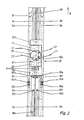
- the device for forming a fabric edge provided with a binding consists of one heald frame 1 and the other heald frame 2 (FIG. 1).
- Each heald frame has two spaced heddle support rails 3 or 3a and 4 or 4a.
- the two heald frames are arranged to move in opposite directions.
- the guide frame On the heald frame 2, i.e. means on the heddle support rail 3 or 3a (not shown), the guide frame, designated overall by 5, is fastened, for example with the aid of clamping pieces 6 and 6a (not shown).
- This guide frame 5 consists in detail of the two frame rails 5a, 5b designed as U-rails, the two frame rails being arranged opposite one another in such a way that a guide groove 7 for guiding the link 9 is thereby formed.
- the needles in the guide frame are designated 7a, 7b, 7c and 7d; they have the eyelets 8a, 8b, 8c and 8d through which the upright or warp threads 16a - 16d are drawn.
- the axes of the eyelets of the needles run according to the running direction of the upright or warp threads.
- the link 9 is arranged to be vertically movable.
- the link 9 has the magnets 11, 12 on its edge in the region of the frame rail 5a.
- a perforated disk 10 is rotatably arranged, which itself is provided with a groove 10a running on the end face is.
- a C-shaped frame 15 with the central part 15a and with legs 15b, 15c adjoining the central part is arranged movably on the link in relation to the latter.
- the central part 15a which has a bore 16 in the form of an elongated hole, projects into the groove 9a of the link as well as into the end groove 10a of the perforated disk 10 rotatably arranged in the link 9.
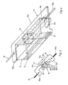
- the rotatability of the perforated disk 10 by the vertical movement of the C-shaped frame is made possible by the fact that recesses 19, 20 (FIG. 3) are provided in the central part 15a on both sides of the bore 16, into which the groove ends of the perforated disk 10 are rotated each shrink.
- cutouts can thus also serve as a stop for limiting the rotation of the perforated disk 10.
- the frame is connected to the perforated disc by a pin 17 which projects through the bore 10c into the bore 16 of the leg 15a.
- the length of the circular arc by which the perforated disc can be rotated corresponds to the maximum distance X from the inner edge of the leg 15c of the C-shaped frame to the adjacent horizontal edge of the link 9.
- the C-shaped frame 15 itself is in this case via traction means 18, 18a connected to the heald frame 2.
- the device works as follows:
- the link 9 is located on the leg 15b of the frame 15 serving as a stop (FIG. 2).
- the thread guiding device is accordingly at the lower end of the guide frame 5.
- the traction means 18 pulls the C-shaped frame 15 in the upward direction (arrow A Fig. 2); there is then first a relative movement of the C-shaped frame 15 to the link 9, whereby the perforated disc 10 is rotated.
- the relative movement of the frame to the backdrop is caused by the fact that the frictional force resulting from the movement of the frame in the backdrop and the rotation of the perforated disk in the backdrop is less than the force exerted by the frame rails on the backdrop.
- This force is composed of the force created by friction between the frame rails and the link and the magnetic force which is generated by the two magnets 11 and 12 arranged in the area of the frame rails.
- the backdrop 9 therefore follows the movement of the frame 15 with a delay.
- the length of the circular arc by which the perforated disk is rotated here corresponds to the inner distance between the two legs 15b, 15c of the frame 15 minus the length of the backdrop.
- the leno threads 21 passed through the four openings 10b - 10e of the perforated disk 10 experience a horizontal movement due to the rotation of the perforated disk, whereby the leno threads are tensioned.
- the thread guide device moves further upwards, the leno threads reach the space between the needle ends, i.e. in the area between the two pairs of needles 7a, 7b on one side and 7c, 7d on the other side, then the leno threads - due to the tension in the horizontal direction - will definitely reach the other side of the opposite needle, which results has that the leno threads can then each take the position required for proper binding.
- the upright threads drawn through the eyelets 8a to 8d always make exactly one vertical movement. The binding comes about through the horizontal movement of the leno threads and the vertical movement of the upright threads.
- a closed frame can also be used instead of the C-shaped frame, the vertical legs of such a frame being guided in corresponding grooves in the backdrop. To be able to use the closed frame in the setting, it must then be divided.
Landscapes
- Engineering & Computer Science (AREA)
- Textile Engineering (AREA)
- Looms (AREA)
- Dicing (AREA)
- Display Devices Of Pinball Game Machines (AREA)
- Prostheses (AREA)
Priority Applications (1)
| Application Number | Priority Date | Filing Date | Title |
|---|---|---|---|
| AT87107807T ATE71995T1 (de) | 1986-06-05 | 1987-05-29 | Vorrichtung zum bilden einer mit einer bindung versehenen gewebekante. |
Applications Claiming Priority (2)
| Application Number | Priority Date | Filing Date | Title |
|---|---|---|---|
| DE19863618946 DE3618946A1 (de) | 1986-06-05 | 1986-06-05 | Vorrichtung zum bilden einer mit einer bindung versehenen gewebekante |
| DE3618946 | 1986-06-05 |
Publications (3)
| Publication Number | Publication Date |
|---|---|
| EP0248364A2 true EP0248364A2 (fr) | 1987-12-09 |
| EP0248364A3 EP0248364A3 (en) | 1989-10-18 |
| EP0248364B1 EP0248364B1 (fr) | 1992-01-22 |
Family
ID=6302344
Family Applications (1)
| Application Number | Title | Priority Date | Filing Date |
|---|---|---|---|
| EP87107807A Expired - Lifetime EP0248364B1 (fr) | 1986-06-05 | 1987-05-29 | Dispositif de formation d'une lisière comportant une liaison |
Country Status (4)
| Country | Link |
|---|---|
| EP (1) | EP0248364B1 (fr) |
| AT (1) | ATE71995T1 (fr) |
| DE (1) | DE3618946A1 (fr) |
| ES (1) | ES2027994T3 (fr) |
Cited By (2)
| Publication number | Priority date | Publication date | Assignee | Title |
|---|---|---|---|---|
| EP1428916A3 (fr) * | 2002-12-10 | 2005-02-09 | Klöcker-Entwicklungs-GmbH | Dispositif pour la formation d'une lisière à pas de gaze |
| CN105714456A (zh) * | 2016-04-16 | 2016-06-29 | 广东康特斯织造装备有限公司 | 多线电子绞边器及其控制方法 |
Family Cites Families (4)
| Publication number | Priority date | Publication date | Assignee | Title |
|---|---|---|---|---|
| CH641847A5 (de) * | 1979-01-20 | 1984-03-15 | Heinz Kloecker | Vorrichtung zum bilden einer mit einer bindung versehenen gewebekante, insbesondere bei schuetzenlosen webmaschinen. |
| DE3108662A1 (de) * | 1981-03-07 | 1982-09-23 | Gebrüder Schmeing, 4280 Borken | Vorrichtung zur herstellung einer gewebe-schnittleiste |
| DE3236035C1 (de) * | 1982-09-29 | 1984-04-05 | Gebrüder Schmeing, 4280 Borken | Vorrichtung zur Herstellung einer Gewebe-Schnittleiste |
| DE3329997A1 (de) * | 1983-08-19 | 1985-03-07 | Gebrüder Klöcker, 4280 Borken | Vorrichtung zum bilden einer dreherkante, insbesondere fuer ein auf schuetzenlosen webmaschinen hergestelltes gewebe |
-
1986
- 1986-06-05 DE DE19863618946 patent/DE3618946A1/de active Granted
-
1987
- 1987-05-29 AT AT87107807T patent/ATE71995T1/de not_active IP Right Cessation
- 1987-05-29 EP EP87107807A patent/EP0248364B1/fr not_active Expired - Lifetime
- 1987-05-29 ES ES198787107807T patent/ES2027994T3/es not_active Expired - Lifetime
Cited By (2)
| Publication number | Priority date | Publication date | Assignee | Title |
|---|---|---|---|---|
| EP1428916A3 (fr) * | 2002-12-10 | 2005-02-09 | Klöcker-Entwicklungs-GmbH | Dispositif pour la formation d'une lisière à pas de gaze |
| CN105714456A (zh) * | 2016-04-16 | 2016-06-29 | 广东康特斯织造装备有限公司 | 多线电子绞边器及其控制方法 |
Also Published As
| Publication number | Publication date |
|---|---|
| DE3618946C2 (fr) | 1989-02-02 |
| EP0248364B1 (fr) | 1992-01-22 |
| ES2027994T3 (es) | 1992-07-01 |
| ATE71995T1 (de) | 1992-02-15 |
| DE3618946A1 (de) | 1987-12-10 |
| EP0248364A3 (en) | 1989-10-18 |
Similar Documents
| Publication | Publication Date | Title |
|---|---|---|
| DE2616910A1 (de) | Vorrichtung zur bildung einer dreherbindungs-webkante auf webstuehlen | |
| EP0107099A1 (fr) | Dispositif de commande d'une lisse individuelle dans un métier à tisser comportant un dispositif de formation de foule | |
| DD201706A5 (de) | Vorrichtung zur herstellung einer ganzdreherbindung der seitenraender eines gewebes in einer webmaschine | |
| DE2622398A1 (de) | Traeger fuer schaftrahmen von webmaschinen | |
| DE19547765A1 (de) | Jacquardmaschine mit Flaschenzugvorrichtung | |
| DE2656380C3 (de) | Vorrichtung zum Verbinden der Schäfte mit der Fachbildevorrichtung einer Webmaschine | |
| EP0267509A2 (fr) | Métier à tisser circulaire | |
| CH641847A5 (de) | Vorrichtung zum bilden einer mit einer bindung versehenen gewebekante, insbesondere bei schuetzenlosen webmaschinen. | |
| DE2329302A1 (de) | Vorrichtung zur gewebekantenbildung an webmaschinen | |
| DE4038256C2 (fr) | ||
| DE3618946C2 (fr) | ||
| EP0174533B1 (fr) | Dispositif d'exécution d'une lisière à pas de gaze | |
| DE68927664T2 (de) | Verfahren zur Herstellung einer Textur mit Dreherbindung | |
| EP0214322A1 (fr) | Dispositif pour la formation du pas de gaze dans les métiers à tisser | |
| DE3830107A1 (de) | Drehervorrichtung fuer webmaschinen | |
| DE8615194U1 (de) | Vorrichtung zum Bilden einer mit einer Bindung versehenen Gewebekante | |
| DE1535393B1 (de) | Vorrichtung fuer Webmaschinen zum Herstellen einer aus zwei Dreherfaeden und einem Bindefaden bestehenden Dreherkante | |
| DE3501636C2 (fr) | ||
| EP1242661B1 (fr) | Dispositif de formation de la foule pour l'industrie textile | |
| DE2505812A1 (de) | Vorrichtung zum herstellen von schlingengewebe | |
| DE3627506C2 (fr) | ||
| DE2754164C2 (de) | Vorrichtung zur Herstellung einer Gewebe-Schnittleiste | |
| EP0502528A1 (fr) | Dispositif de palonnier pour monter ou abaisser au moins un fil de chaîne dans une machine jacquard, en particulier une machine à foule ouverte | |
| DE1710317C3 (de) | Verfahren und Vorrichtung zum Herstellen einer Dreherbindung | |
| DE4204629C1 (fr) |
Legal Events
| Date | Code | Title | Description |
|---|---|---|---|
| PUAI | Public reference made under article 153(3) epc to a published international application that has entered the european phase |
Free format text: ORIGINAL CODE: 0009012 |
|
| 17P | Request for examination filed |
Effective date: 19870622 |
|
| AK | Designated contracting states |
Kind code of ref document: A2 Designated state(s): AT BE CH ES FR GB IT LI |
|
| PUAL | Search report despatched |
Free format text: ORIGINAL CODE: 0009013 |
|
| AK | Designated contracting states |
Kind code of ref document: A3 Designated state(s): AT BE CH ES FR GB IT LI |
|
| RHK1 | Main classification (correction) |
Ipc: D03C 7/00 |
|
| 17Q | First examination report despatched |
Effective date: 19910222 |
|
| GRAA | (expected) grant |
Free format text: ORIGINAL CODE: 0009210 |
|
| AK | Designated contracting states |
Kind code of ref document: B1 Designated state(s): AT BE CH ES FR GB IT LI |
|
| REF | Corresponds to: |
Ref document number: 71995 Country of ref document: AT Date of ref document: 19920215 Kind code of ref document: T |
|
| ITF | It: translation for a ep patent filed | ||
| ET | Fr: translation filed | ||
| GBT | Gb: translation of ep patent filed (gb section 77(6)(a)/1977) | ||
| ITTA | It: last paid annual fee | ||
| REG | Reference to a national code |
Ref country code: ES Ref legal event code: FG2A Ref document number: 2027994 Country of ref document: ES Kind code of ref document: T3 |
|
| PLBE | No opposition filed within time limit |
Free format text: ORIGINAL CODE: 0009261 |
|
| STAA | Information on the status of an ep patent application or granted ep patent |
Free format text: STATUS: NO OPPOSITION FILED WITHIN TIME LIMIT |
|
| 26N | No opposition filed | ||
| PGFP | Annual fee paid to national office [announced via postgrant information from national office to epo] |
Ref country code: BE Payment date: 19930330 Year of fee payment: 7 |
|
| PGFP | Annual fee paid to national office [announced via postgrant information from national office to epo] |
Ref country code: ES Payment date: 19930407 Year of fee payment: 7 |
|
| PGFP | Annual fee paid to national office [announced via postgrant information from national office to epo] |
Ref country code: AT Payment date: 19930513 Year of fee payment: 7 |
|
| PGFP | Annual fee paid to national office [announced via postgrant information from national office to epo] |
Ref country code: CH Payment date: 19930517 Year of fee payment: 7 |
|
| PGFP | Annual fee paid to national office [announced via postgrant information from national office to epo] |
Ref country code: GB Payment date: 19930521 Year of fee payment: 7 |
|
| PGFP | Annual fee paid to national office [announced via postgrant information from national office to epo] |
Ref country code: FR Payment date: 19930527 Year of fee payment: 7 |
|
| PG25 | Lapsed in a contracting state [announced via postgrant information from national office to epo] |
Ref country code: GB Effective date: 19940529 Ref country code: AT Effective date: 19940529 |
|
| PG25 | Lapsed in a contracting state [announced via postgrant information from national office to epo] |
Ref country code: ES Free format text: LAPSE BECAUSE OF NON-PAYMENT OF DUE FEES Effective date: 19940530 |
|
| PG25 | Lapsed in a contracting state [announced via postgrant information from national office to epo] |
Ref country code: LI Effective date: 19940531 Ref country code: CH Effective date: 19940531 Ref country code: BE Effective date: 19940531 |
|
| BERE | Be: lapsed |
Owner name: KLOCKER-ENTWICKLUNGS G.M.B.H. Effective date: 19940531 |
|
| GBPC | Gb: european patent ceased through non-payment of renewal fee |
Effective date: 19940529 |
|
| PG25 | Lapsed in a contracting state [announced via postgrant information from national office to epo] |
Ref country code: FR Effective date: 19950131 |
|
| REG | Reference to a national code |
Ref country code: CH Ref legal event code: PL |
|
| REG | Reference to a national code |
Ref country code: FR Ref legal event code: ST |
|
| REG | Reference to a national code |
Ref country code: ES Ref legal event code: FD2A Effective date: 19990201 |
|
| PG25 | Lapsed in a contracting state [announced via postgrant information from national office to epo] |
Ref country code: IT Free format text: LAPSE BECAUSE OF NON-PAYMENT OF DUE FEES Effective date: 20050529 |