EP0247935B1 - Zuleitungsverfahren für einen Joule-Thomson-Kühler und Kühlvorrichtung zu seiner Durchführung - Google Patents
Zuleitungsverfahren für einen Joule-Thomson-Kühler und Kühlvorrichtung zu seiner Durchführung Download PDFInfo
- Publication number
- EP0247935B1 EP0247935B1 EP19870401167 EP87401167A EP0247935B1 EP 0247935 B1 EP0247935 B1 EP 0247935B1 EP 19870401167 EP19870401167 EP 19870401167 EP 87401167 A EP87401167 A EP 87401167A EP 0247935 B1 EP0247935 B1 EP 0247935B1
- Authority
- EP
- European Patent Office
- Prior art keywords
- pressure
- fluid
- flow
- rate
- working fluid
- Prior art date
- Legal status (The legal status is an assumption and is not a legal conclusion. Google has not performed a legal analysis and makes no representation as to the accuracy of the status listed.)
- Expired - Lifetime
Links
- 238000001816 cooling Methods 0.000 title claims description 33
- 238000000034 method Methods 0.000 title claims description 16
- 239000012530 fluid Substances 0.000 claims description 41
- 230000007423 decrease Effects 0.000 claims description 6
- 239000007788 liquid Substances 0.000 claims description 3
- 230000037452 priming Effects 0.000 claims 3
- XKRFYHLGVUSROY-UHFFFAOYSA-N Argon Chemical compound [Ar] XKRFYHLGVUSROY-UHFFFAOYSA-N 0.000 description 30
- IJGRMHOSHXDMSA-UHFFFAOYSA-N Atomic nitrogen Chemical compound N#N IJGRMHOSHXDMSA-UHFFFAOYSA-N 0.000 description 30
- 229910052786 argon Inorganic materials 0.000 description 15
- 229910052757 nitrogen Inorganic materials 0.000 description 15
- 230000000694 effects Effects 0.000 description 6
- 239000007789 gas Substances 0.000 description 4
- 238000009835 boiling Methods 0.000 description 3
- 239000011888 foil Substances 0.000 description 3
- 238000005192 partition Methods 0.000 description 3
- 238000011144 upstream manufacturing Methods 0.000 description 3
- 238000004804 winding Methods 0.000 description 3
- 229910000831 Steel Inorganic materials 0.000 description 1
- 230000001133 acceleration Effects 0.000 description 1
- 229910052790 beryllium Inorganic materials 0.000 description 1
- 238000010586 diagram Methods 0.000 description 1
- 230000000873 masking effect Effects 0.000 description 1
- 239000010959 steel Substances 0.000 description 1
- 238000009834 vaporization Methods 0.000 description 1
- 230000008016 vaporization Effects 0.000 description 1
Images


Classifications
-
- F—MECHANICAL ENGINEERING; LIGHTING; HEATING; WEAPONS; BLASTING
- F25—REFRIGERATION OR COOLING; COMBINED HEATING AND REFRIGERATION SYSTEMS; HEAT PUMP SYSTEMS; MANUFACTURE OR STORAGE OF ICE; LIQUEFACTION SOLIDIFICATION OF GASES
- F25B—REFRIGERATION MACHINES, PLANTS OR SYSTEMS; COMBINED HEATING AND REFRIGERATION SYSTEMS; HEAT PUMP SYSTEMS
- F25B9/00—Compression machines, plants or systems, in which the refrigerant is air or other gas of low boiling point
- F25B9/02—Compression machines, plants or systems, in which the refrigerant is air or other gas of low boiling point using Joule-Thompson effect; using vortex effect
-
- F—MECHANICAL ENGINEERING; LIGHTING; HEATING; WEAPONS; BLASTING
- F25—REFRIGERATION OR COOLING; COMBINED HEATING AND REFRIGERATION SYSTEMS; HEAT PUMP SYSTEMS; MANUFACTURE OR STORAGE OF ICE; LIQUEFACTION SOLIDIFICATION OF GASES
- F25B—REFRIGERATION MACHINES, PLANTS OR SYSTEMS; COMBINED HEATING AND REFRIGERATION SYSTEMS; HEAT PUMP SYSTEMS
- F25B2309/00—Gas cycle refrigeration machines
- F25B2309/02—Gas cycle refrigeration machines using the Joule-Thompson effect
- F25B2309/022—Gas cycle refrigeration machines using the Joule-Thompson effect characterised by the expansion element
Definitions
- the present invention relates to a method for supplying a Joule-Thomson cooler comprising a high pressure line which ends in a pressure relief port, and a low pressure discharge circuit in heat exchange relation with the high line pressure and into which the expansion orifice opens, and more particularly to a method of the type in which the high pressure pipe is successively supplied with a starting fluid and then with a working fluid.
- the object of the invention is to make it possible to obtain in a very short time lower temperatures which it has not been possible to reach until now.
- the subject of the invention is a method of the type in which the high-pressure pipe is successively supplied with a starting fluid and then with a working fluid and is characterized in that one passes from the starting fluid to the work when the speed of cooling provided by the first fluid becomes lower than the speed of cooling provided by the second fluid, and in that the working fluid is used first at a high flow rate, then its flow is suddenly reduced to finish the cooling phase of the cooler.
- the method according to the invention therefore comprises three distinct, successive stages, which together form the cooling phase of the cooler: (1) starting fluid, (2) working fluid at high flow rate, and (3) working fluid at low flow, whereas the previous documents describe either a cooling by steps (1) and (2), or the use alone of steps (2) and (3).
- the invention provides that there is a change from starting fluid to working fluid when the cooling speed provided by the first fluid becomes lower than the cooling speed provided by the second fluid.
- the start of the intervention of the working fluid corresponds to an acceleration of the cooling, thanks to the particular choice of the moment of switching from one fluid to another.
- the invention also relates to a cooling device intended to implement the method defined above.
- This apparatus of the type comprising a first source of starting fluid under a first high pressure, a second source of working fluid under a second high pressure, a Joule-Thomson cooler comprises a high pressure line which ends in a relief orifice and a low pressure discharge circuit in heat exchange relationship with the high pressure pipe and into which the expansion orifice opens, and switching means for connecting the high pressure pipe first to the first source and then to the second source, is characterized in that it comprises throttling means for abruptly reducing the flow rate flowing in the high pressure pipe, with a shutter with low clearance, movable from a first position where the expansion orifice is free at a second position where this expansion orifice is masked by a surface of the shutter leaving a leakage passage at the periphery of the orifice, ai nsi only means for instantly passing the shutter from its first position to its second position.
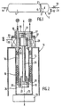
- the reservoir 1 shown in FIG. 1 is divided into two unequal chambers by a transverse partition 2: a downstream auxiliary chamber 3 containing a starting fluid with Joule-Thomson effect which is large but relatively not very volatile, for example argon, under a first high pressure which can be of the order of 700 bars, and an upstream main chamber 4 containing a more volatile working fluid and with a lesser Joule-Thomson effect, for example nitrogen, under a second high pressure at most equal at the first high pressure, for example of the order of 400 bars.
- a transverse partition 2 a downstream auxiliary chamber 3 containing a starting fluid with Joule-Thomson effect which is large but relatively not very volatile, for example argon, under a first high pressure which can be of the order of 700 bars, and an upstream main chamber 4 containing a more volatile working fluid and with a lesser Joule-Thomson effect, for example nitrogen, under a second high pressure at most equal at the first high pressure, for example of the order of 400 bars.
- the partition 2 is pierced with an orifice 5 masked by a piece of foil 6 applied to the front face of the partition.
- From the downstream chamber 3 leaves an outlet pipe 9 provided with a stop valve 10 and on which is stuck, upstream of the valve 10, a pipe 11 for filling with argon itself provided with a valve stop 12.
- the cooler shown in Figures 2 and 3 is of revolution about an axis X-X, assumed to be vertical for the convenience of the description, and comprises an inner tubular core 13 and a double outer casing 14 exposed under vacuum and forming Dewar.
- An upper head 15 in the form of an inverted cup closes the upper end of the core 13 and of the annular space 16 between the core 13 and the casing 14; the space 16 however communicates with the surrounding atmosphere through a series of holes 17 passing through the head 15.
- the internal diameters of the core 13 of the envelope 14 are approximately 2.5 mm and 5 mm respectively.
- a sheath 18 is partially threaded and fixed in the lower end of the core 13.
- the inner wall of the envelope 14 carries at its lower end a bottom 22 on which is fixed in heat exchange contact an element 23 to be cooled, which can for example be an infrared detector and which is located in the vacuum space of the Dewar. Above the bottom 22 is thus defined a cooling chamber 24 which constitutes the coldest part of the device.
- a rod 25 is slidably mounted inside the core 13.
- This rod carries at its lower end a shutter needle 26 and, at its upper end, an electromagnet plunger 27.
- the needle 26 slides with narrow adjustment in the sleeve 19, that is to say with a clearance which, taking into account the coefficients of expansion, is, on the diameter, of the order of a few microns for the cold operating temperature of the cooler.
- a clearance which, taking into account the coefficients of expansion, is, on the diameter, of the order of a few microns for the cold operating temperature of the cooler.
- the needle is made of 100 C 6 steel and the sheath is made of bronze-beryllium, there will be a clearance, on the diameter, of 5 to 6 microns at room temperature, which corresponds to a clearance, on the diameter , from 2 to 3 microns at a cold temperature of the order of 80 to 90 K.
- the plunger 27 slides in the head 15. Around the latter is arranged an electromagnet winding 28, the terminals 29, 30 of which are adapted to be connected to the terminals of a direct current source (not shown).
- a spring 31 is compressed axially between the bottom of the head 15 and the plunger 27.
- the rod 25 is guided on the one hand by the needle 26, on the other hand by the plunger 27.
- a stop 32 for the plunger 27 is provided at the outlet of the head 15.
- the cooler At rest, the cooler is in the state shown in Figure 3: the electromagnet is not supplied with electric current, so that the spring 31 is relaxed and pushes down the rod 27 to a stop position where the needle 26 closes the orifice 21 to the nearest sliding clearance (5 to 6 microns on the diameter since the device is at room temperature).
- the valve 10 of the line 9 is opened, so that the argon under high pressure is sent into the line 19 and is expanded at high flow rate (for example 1000 to 1500 NI / h) at the passage of the orifice 21.
- high flow rate for example 1000 to 1500 NI / h
- the expanded and consequently cooled argon rises between the turns of the pipe 19 until it is discharged into the surrounding atmosphere through the orifices 17, cooling the high pressure argon.
- the temperature prevailing in the chamber 24 decreases more and more.
- the pressure drops in chamber 3 of the tank.
- the pressure of chamber 3 is sufficiently lower than that of chamber 4 (400 bars in this example) to cause rupture of the foil 6.
- the nitrogen contained in chamber 4 then flushes out Almost instantaneously from the reservoir, the remainder of argon, then flows at a high flow rate (for example 600 to 800 NI / h) in line 19 to relax as the orifice 21 passes.
- a high flow rate for example 600 to 800 NI / h
- the electrical supply to the winding 28 is cut off, for example by means of a timer, so that the spring 31 instantly returns the rod 25 to its initial position in FIG. 3: the needle 26 closes the orifice 21 and, being pushed laterally by the gas jet leaving this orifice, is at a distance from the latter equal to the diametral clearance at low temperature, ie 2 to 3 microns with the numerical values indicated above.
- the flow is thus suddenly reduced to a low value, preferably this at least ten times lower than its previous value; the pressure drop of the low pressure circuit, which was of the order of a few bars, is reduced by the same amount, which makes it possible to obtain, in chamber 24, liquid nitrogen at a temperature close to the boiling point of nitrogen at atmospheric pressure, i.e. around 80 K.
- FIG. 4 shows the variation of the temperature in the chamber 24 as a function of time.
- cooling results solely from the expansion of the argon at high flow rates. As this gas has a significant Joule-Thomson effect, this cooling is very rapid.
- This time can be chosen to abruptly decrease the nitrogen flow (time t2).
- the final curve C3 of FIG. 4 is then obtained, which is parallel to the curve C4 corresponding to the case where the entire cooling operation is carried out with nitrogen at low flow rate.
- This curve C3 is very satisfactory if it is desired to reach a final temperature of between 85 and 90 K. But to descend lower in temperature, it is preferable to allow the nitrogen to flow at a high rate until an instant t3 , posterior to t2, where a certain amount of nitrogen under a few bars has formed in the chamber 24 (point D of FIG. 4). In this case, the reduction in the nitrogen flow causes a very rapid vaporization of part of this liquid (flash effect), the temperature of which drops almost instantaneously in the vicinity of 80 K. We then obtain the final curve C5 of Figure 4.
Landscapes
- Engineering & Computer Science (AREA)
- Physics & Mathematics (AREA)
- Mechanical Engineering (AREA)
- Thermal Sciences (AREA)
- General Engineering & Computer Science (AREA)
Claims (6)
Applications Claiming Priority (2)
| Application Number | Priority Date | Filing Date | Title |
|---|---|---|---|
| FR8607449 | 1986-05-26 | ||
| FR8607449A FR2599128A1 (fr) | 1986-05-26 | 1986-05-26 | Procede d'alimentation d'un refroidisseur joule-thomson et appareil de refroidissement pour sa mise en oeuvre |
Publications (2)
| Publication Number | Publication Date |
|---|---|
| EP0247935A1 EP0247935A1 (de) | 1987-12-02 |
| EP0247935B1 true EP0247935B1 (de) | 1990-04-25 |
Family
ID=9335590
Family Applications (1)
| Application Number | Title | Priority Date | Filing Date |
|---|---|---|---|
| EP19870401167 Expired - Lifetime EP0247935B1 (de) | 1986-05-26 | 1987-05-25 | Zuleitungsverfahren für einen Joule-Thomson-Kühler und Kühlvorrichtung zu seiner Durchführung |
Country Status (4)
| Country | Link |
|---|---|
| EP (1) | EP0247935B1 (de) |
| DE (1) | DE3762452D1 (de) |
| ES (1) | ES2015309B3 (de) |
| FR (1) | FR2599128A1 (de) |
Families Citing this family (2)
| Publication number | Priority date | Publication date | Assignee | Title |
|---|---|---|---|---|
| DE19812725A1 (de) * | 1998-03-24 | 1999-09-30 | Bodenseewerk Geraetetech | Verfahren und Vorrichtung zum Kühlen von Bauteilen, insbesondere von Infrarot-Detektoren bei Suchköpfen |
| RU2729251C2 (ru) | 2015-06-25 | 2020-08-05 | Общество с ограниченной ответственностью "ИРБИС ТЕХНОЛОГИИ" (ООО "ИРБИСТЕХ") | Способы и устройства для производства гранулированного твердого диоксида углерода (варианты) |
Family Cites Families (15)
| Publication number | Priority date | Publication date | Assignee | Title |
|---|---|---|---|---|
| US2991633A (en) * | 1958-03-17 | 1961-07-11 | Itt | Joule-thomson effect cooling system |
| US3095711A (en) * | 1962-01-31 | 1963-07-02 | Jr Howard P Wurtz | Double cryostat |
| US3320755A (en) * | 1965-11-08 | 1967-05-23 | Air Prod & Chem | Cryogenic refrigeration system |
| US3942010A (en) * | 1966-05-09 | 1976-03-02 | The United States Of America As Represented By The Secretary Of The Navy | Joule-Thomson cryostat cooled infrared cell having a built-in thermostat sensing element |
| US3413819A (en) * | 1966-05-09 | 1968-12-03 | Hughes Aircraft Co | Flow rate control for a joule-thomson refrigerator |
| US3415078A (en) * | 1967-07-31 | 1968-12-10 | Gen Dynamics Corp | Infrared detector cooler |
| GB1318023A (en) * | 1970-06-17 | 1973-05-23 | Hymatic Eng Co Ltd | Cryogenic cooling apparatus |
| US3714796A (en) * | 1970-07-30 | 1973-02-06 | Air Prod & Chem | Cryogenic refrigeration system with dual circuit heat exchanger |
| FR2176544B1 (de) * | 1972-03-23 | 1982-02-19 | Air Liquide | |
| FR2322337A1 (fr) * | 1975-08-26 | 1977-03-25 | Air Liquide | Dispositif d'alimentation de refrigerant d'un refrigerateur a circuit ouvert, et systeme de refrigeration comportant un tel dispositif |
| DE7626566U1 (de) * | 1975-08-26 | 1977-02-03 | L'air Liquide, S.A. Pour L'etude Et L'exploitation Des Procedes Georges Claude, Paris | Vorrichtung zur speisung einer miniaturkaeltemaschine und kuehlvorrichtung |
| DE2806829C3 (de) * | 1978-02-17 | 1984-09-20 | Deutsche Forschungs- Und Versuchsanstalt Fuer Luft- Und Raumfahrt E.V., 5000 Koeln | Vorrichtung zur Tiefstkühlung von Objekten |
| US4237699A (en) * | 1979-05-23 | 1980-12-09 | Air Products And Chemicals, Inc. | Variable flow cryostat with dual orifice |
| GB2085139A (en) * | 1980-10-10 | 1982-04-21 | Hymatic Engineering The Co Ltd | Cryogenic cooling apparatus |
| FR2520131B1 (fr) * | 1982-01-19 | 1985-09-20 | Telecommunications Sa | Dispositif de regulation d'un refrigerateur a effet joule-thomson |
-
1986
- 1986-05-26 FR FR8607449A patent/FR2599128A1/fr not_active Withdrawn
-
1987
- 1987-05-25 EP EP19870401167 patent/EP0247935B1/de not_active Expired - Lifetime
- 1987-05-25 ES ES87401167T patent/ES2015309B3/es not_active Expired - Lifetime
- 1987-05-25 DE DE8787401167T patent/DE3762452D1/de not_active Expired - Lifetime
Also Published As
| Publication number | Publication date |
|---|---|
| FR2599128A1 (fr) | 1987-11-27 |
| DE3762452D1 (de) | 1990-05-31 |
| ES2015309B3 (es) | 1990-08-16 |
| EP0247935A1 (de) | 1987-12-02 |
Similar Documents
| Publication | Publication Date | Title |
|---|---|---|
| FR2801648A1 (fr) | Injecteur a vapeur haute pression comportant un drain axial | |
| CA2910293A1 (fr) | Procede et dispositif de ravitaillement en liquide cryogenique, notamment en gaz naturel liquefie | |
| EP0798469A1 (de) | Druckwasserzufuhranlage für die Wasserquelle eines Dampfinjektors | |
| CA1228797A (fr) | Appareil pour fournir un filet continu d'un liquide cryogenique, notamment d'azote liquide | |
| EP0247935B1 (de) | Zuleitungsverfahren für einen Joule-Thomson-Kühler und Kühlvorrichtung zu seiner Durchführung | |
| FR2594209A1 (fr) | Procede et installation pour fournir de l'anhydride carbonique sous haute pression | |
| EP0084308B1 (de) | Regelvorrichtung für eine nach dem Joule-Thomson-Effekt arbeitende Kühleinrichtung | |
| EP0245164B1 (de) | Joule-Thomson-Kühler | |
| EP0388277B1 (de) | Joule-Thomson-Kühlvorrichtung | |
| FR2652426A1 (fr) | Detendeur de bouteille de gaz. | |
| EP0186560A1 (de) | Verfahren und Vorrichtung zur Erzeugung eines Plasmabogens | |
| EP0066510B1 (de) | Vorrichtung zur Speicherung und Erzeugung von Wasserstoff aus einer festen Verbindung | |
| EP0359620B1 (de) | Verfahren und Behälter zum Abliefern vom superkritischen Kohlendioxid | |
| EP0179710A1 (de) | Verfahren und Vorrichtung zum Erzeugen eines Gemisches von Substanzen mit niedrigen Siedepunkten | |
| CA1087409A (fr) | Systeme d'echange thermique a fluide frigorigene | |
| WO1980002874A1 (fr) | Dispositif de mesure et de controle de debits gazeux | |
| EP0305257B1 (de) | Verfahren und Vorrichtung zur Kryokühlung eines Objekts | |
| EP0029791A1 (de) | Sicherheits-Gasfeuerzeug | |
| EP0128129A2 (de) | Ventil, insbesondere für Flüssiggas | |
| FR2599119A1 (fr) | Procede et dispositif pour delivrer de petites quantites d'un liquide cryogenique | |
| FR2779212A1 (fr) | Reservoir de stockage de co2 liquide et procede de remplissage de ce reservoir | |
| FR2765966A1 (fr) | Procede et dispositif pour determiner la masse volumique d'un gaz | |
| EP0022422A1 (de) | Spender für kalte kohlensäurehaltige Getränke | |
| FR2558938A1 (fr) | Appareil de refroidissement cryogenique | |
| FR2828273A1 (fr) | Procede d'alimentation en air epure d'une unite de distillation d'air cryogenique et installation de mise en oeuvre de ce procede |
Legal Events
| Date | Code | Title | Description |
|---|---|---|---|
| PUAI | Public reference made under article 153(3) epc to a published international application that has entered the european phase |
Free format text: ORIGINAL CODE: 0009012 |
|
| 17P | Request for examination filed |
Effective date: 19870529 |
|
| AK | Designated contracting states |
Kind code of ref document: A1 Designated state(s): BE CH DE ES FR GB IT LI |
|
| 17Q | First examination report despatched |
Effective date: 19881122 |
|
| GRAA | (expected) grant |
Free format text: ORIGINAL CODE: 0009210 |
|
| AK | Designated contracting states |
Kind code of ref document: B1 Designated state(s): BE CH DE ES FR GB IT LI |
|
| ITF | It: translation for a ep patent filed | ||
| REF | Corresponds to: |
Ref document number: 3762452 Country of ref document: DE Date of ref document: 19900531 |
|
| GBT | Gb: translation of ep patent filed (gb section 77(6)(a)/1977) | ||
| PLBE | No opposition filed within time limit |
Free format text: ORIGINAL CODE: 0009261 |
|
| STAA | Information on the status of an ep patent application or granted ep patent |
Free format text: STATUS: NO OPPOSITION FILED WITHIN TIME LIMIT |
|
| 26N | No opposition filed | ||
| ITTA | It: last paid annual fee | ||
| PGFP | Annual fee paid to national office [announced via postgrant information from national office to epo] |
Ref country code: FR Payment date: 19970411 Year of fee payment: 11 |
|
| PGFP | Annual fee paid to national office [announced via postgrant information from national office to epo] |
Ref country code: GB Payment date: 19970417 Year of fee payment: 11 |
|
| PGFP | Annual fee paid to national office [announced via postgrant information from national office to epo] |
Ref country code: DE Payment date: 19970423 Year of fee payment: 11 Ref country code: BE Payment date: 19970423 Year of fee payment: 11 |
|
| PGFP | Annual fee paid to national office [announced via postgrant information from national office to epo] |
Ref country code: CH Payment date: 19970501 Year of fee payment: 11 |
|
| PGFP | Annual fee paid to national office [announced via postgrant information from national office to epo] |
Ref country code: ES Payment date: 19970513 Year of fee payment: 11 |
|
| PG25 | Lapsed in a contracting state [announced via postgrant information from national office to epo] |
Ref country code: GB Free format text: LAPSE BECAUSE OF NON-PAYMENT OF DUE FEES Effective date: 19980525 |
|
| PG25 | Lapsed in a contracting state [announced via postgrant information from national office to epo] |
Ref country code: ES Free format text: LAPSE BECAUSE OF EXPIRATION OF PROTECTION Effective date: 19980526 |
|
| PG25 | Lapsed in a contracting state [announced via postgrant information from national office to epo] |
Ref country code: LI Free format text: LAPSE BECAUSE OF NON-PAYMENT OF DUE FEES Effective date: 19980531 Ref country code: FR Free format text: LAPSE BECAUSE OF NON-PAYMENT OF DUE FEES Effective date: 19980531 Ref country code: CH Free format text: LAPSE BECAUSE OF NON-PAYMENT OF DUE FEES Effective date: 19980531 Ref country code: BE Free format text: LAPSE BECAUSE OF NON-PAYMENT OF DUE FEES Effective date: 19980531 |
|
| BERE | Be: lapsed |
Owner name: S.A. L' AIR LIQUIDE POUR L'ETUDE ET L'EXPLOITATION Effective date: 19980531 |
|
| GBPC | Gb: european patent ceased through non-payment of renewal fee |
Effective date: 19980525 |
|
| REG | Reference to a national code |
Ref country code: CH Ref legal event code: PL |
|
| PG25 | Lapsed in a contracting state [announced via postgrant information from national office to epo] |
Ref country code: DE Free format text: LAPSE BECAUSE OF NON-PAYMENT OF DUE FEES Effective date: 19990302 |
|
| REG | Reference to a national code |
Ref country code: FR Ref legal event code: ST |
|
| REG | Reference to a national code |
Ref country code: ES Ref legal event code: FD2A Effective date: 20000301 |
|
| PG25 | Lapsed in a contracting state [announced via postgrant information from national office to epo] |
Ref country code: IT Free format text: LAPSE BECAUSE OF NON-PAYMENT OF DUE FEES Effective date: 20050525 |