EP0128129A2 - Ventil, insbesondere für Flüssiggas - Google Patents
Ventil, insbesondere für Flüssiggas Download PDFInfo
- Publication number
- EP0128129A2 EP0128129A2 EP84870050A EP84870050A EP0128129A2 EP 0128129 A2 EP0128129 A2 EP 0128129A2 EP 84870050 A EP84870050 A EP 84870050A EP 84870050 A EP84870050 A EP 84870050A EP 0128129 A2 EP0128129 A2 EP 0128129A2
- Authority
- EP
- European Patent Office
- Prior art keywords
- register
- valve
- valve according
- temperature
- damper
- Prior art date
- Legal status (The legal status is an assumption and is not a legal conclusion. Google has not performed a legal analysis and makes no representation as to the accuracy of the status listed.)
- Withdrawn
Links
Images


Classifications
-
- F—MECHANICAL ENGINEERING; LIGHTING; HEATING; WEAPONS; BLASTING
- F17—STORING OR DISTRIBUTING GASES OR LIQUIDS
- F17C—VESSELS FOR CONTAINING OR STORING COMPRESSED, LIQUEFIED OR SOLIDIFIED GASES; FIXED-CAPACITY GAS-HOLDERS; FILLING VESSELS WITH, OR DISCHARGING FROM VESSELS, COMPRESSED, LIQUEFIED, OR SOLIDIFIED GASES
- F17C13/00—Details of vessels or of the filling or discharging of vessels
- F17C13/02—Special adaptations of indicating, measuring, or monitoring equipment
- F17C13/021—Special adaptations of indicating, measuring, or monitoring equipment having the height as the parameter
-
- F—MECHANICAL ENGINEERING; LIGHTING; HEATING; WEAPONS; BLASTING
- F17—STORING OR DISTRIBUTING GASES OR LIQUIDS
- F17C—VESSELS FOR CONTAINING OR STORING COMPRESSED, LIQUEFIED OR SOLIDIFIED GASES; FIXED-CAPACITY GAS-HOLDERS; FILLING VESSELS WITH, OR DISCHARGING FROM VESSELS, COMPRESSED, LIQUEFIED, OR SOLIDIFIED GASES
- F17C13/00—Details of vessels or of the filling or discharging of vessels
- F17C13/04—Arrangement or mounting of valves
-
- F—MECHANICAL ENGINEERING; LIGHTING; HEATING; WEAPONS; BLASTING
- F17—STORING OR DISTRIBUTING GASES OR LIQUIDS
- F17C—VESSELS FOR CONTAINING OR STORING COMPRESSED, LIQUEFIED OR SOLIDIFIED GASES; FIXED-CAPACITY GAS-HOLDERS; FILLING VESSELS WITH, OR DISCHARGING FROM VESSELS, COMPRESSED, LIQUEFIED, OR SOLIDIFIED GASES
- F17C2205/00—Vessel construction, in particular mounting arrangements, attachments or identifications means
- F17C2205/03—Fluid connections, filters, valves, closure means or other attachments
- F17C2205/0302—Fittings, valves, filters, or components in connection with the gas storage device
- F17C2205/0323—Valves
-
- F—MECHANICAL ENGINEERING; LIGHTING; HEATING; WEAPONS; BLASTING
- F17—STORING OR DISTRIBUTING GASES OR LIQUIDS
- F17C—VESSELS FOR CONTAINING OR STORING COMPRESSED, LIQUEFIED OR SOLIDIFIED GASES; FIXED-CAPACITY GAS-HOLDERS; FILLING VESSELS WITH, OR DISCHARGING FROM VESSELS, COMPRESSED, LIQUEFIED, OR SOLIDIFIED GASES
- F17C2205/00—Vessel construction, in particular mounting arrangements, attachments or identifications means
- F17C2205/03—Fluid connections, filters, valves, closure means or other attachments
- F17C2205/0302—Fittings, valves, filters, or components in connection with the gas storage device
- F17C2205/0382—Constructional details of valves, regulators
Definitions
- the invention relates to a gas or liquid valve, more particularly for a pressure tank of gases made at least partially liquid, such as the so-called LPG tank, with a seat provided in a casing, a valve movable relative to the latter. and means for indicating a determined degree of filling of the tank on which the valve is mounted.
- valves of this type it is generally used, to indicate a determined degree of filling of the tank, on which they are mounted, floats actuated either mechanically or electronically.
- the main object of the invention is to eliminate these significant drawbacks and to offer a gas or liquid valve operating automatically, the means for indicating a determined degree of filling comprise no component. movable in the tank and also make it possible, when the adjusted filling level is reached, to automatically bring the valve to a closed position, so that any further filling of the tank is impossible as long as the filling level adjusted is maintained.
- LPG tanks for vehicles which, according to legal requirements, which are applicable in most countries, can only be filled to a certain level below the maximum level, for example up to 80%, with liquid LPG gas.
- the valve above the valve according to the invention is formed by a register which is movable back and forth relative to the seat in the housing, which register in the closed position, s s applied against this seat, and closes a variable intake opening as a function of the position of the damper in the casing towards the latter and, in an open equilibrium position, partially opens the intake opening together with at least one passage opening which is connected with the latter, which is in turn connected or coincides with an outlet opening of the casing, as a function of the pressure exerted on the head of the damper, against the restoring force of an elastic member, a temperature sensitive element being provided and cooperating with the register and, under the influence of a change in temperature, moving the latter in the casing and closing the outlet opening.
- an expansion chamber which can be connected to a reservoir on which the valve is mounted, so that due to an approximately adiabatic expansion in this chamber. a determined quantity of liquid or gas coming from this reservoir, a reduction in temperature is caused, means being provided for transmitting this reduction in temperature to the element sensitive to the aforementioned temperature.
- the expansion chamber is provided in the casing and the temperature-sensitive element is mounted in this expansion chamber.
- the damper is approximately cylindrical and inside this latter is provided a connecting channel, approximately in its direction of movement in the housing, which extends between the opening d inlet and outlet opening of the housing, the expansion chamber being provided between the side wall of this cylindrical register and the housing and the elastic member being formed by a helical spring which extends coaxially around the register and acts together with the temperature sensitive element, which is located in the expansion chamber, on the register in a direction opposite to that of the pressure exerted at the level of the intake opening on the register.
- the invention also relates to a tank, more particularly an LPG tank, which is equipped with the automatic operation valve described above.
- valve shown in the figures is mainly intended for so-called LPG ("liquid petroleum gas”) tanks of motor vehicles, although the invention is in no way limited to this particular form and the valve according to the invention can be applied in principle to all tanks of gases made liquid under pressure, such as ammonia, propane, butane, oxygen, and the like.
- LPG liquid petroleum gas
- the essential principle on which the operation of the valve according to the invention is based consists in using the rapid decrease in temperature which appears by the adiabatic expansion of a liquid being under pressure until a gaseous state.
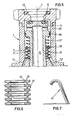
- the embodiment illustrated in Figures 1 to 4, of the gas or liquid valve is mainly formed by an approximately cylindrical casing 1 and a valve 2 in the form of a damper which can be moved back and forth relative to to a seat 3 provided above the latter, along the axis 4 of this casing.
- This register is also made approximately cylindrically and has a head 5 which is applied to the lower part against the seat 3, by means of an annular packing 6, when it is in the closed position, so that it closes an annular inlet opening 7.
- the passage of this inlet opening 7, as can easily be determined, is variable as a function of the position of the damper 2 in the casing 1.
- the damper 2 opens this intake opening 7 together with a passage opening 8 which is in communication with the latter, which in turn is connected with an outlet or exhaust opening 9 provided in the lower part of the casing.
- the degree of opening of these two openings 7 and 8 is a function of the pressure P d exerted on the head 5 of the register 2, against the return force P of an elastic member 10.
- the elastic member is simultaneously a temperature-sensitive element which cooperates with the register 2 and under the influence of a temperature variation, more particularly a decrease in temperature, displaces the latter in the casing in the direction of the pressure exerted P d , so that the outlet opening 9 is closed.
- an expansion chamber 11 has been provided which, via a supply line 12, is connected to the internal volume 13 of a reservoir 14 on which the casing 1 of the valve is mounted.
- the temperature-sensitive element which is therefore formed in this particular embodiment by the elastic member 10, is mounted directly in this expansion chamber.
- the temperature-sensitive element is formed by a helical contraction spring known per se or a helical spring made of memory alloy, this form also known per se, such as for example determined alloys Ni-Ti or Cu-Zn-Al whose spring tension decreases under the influence of a decrease in temperature.
- the damper 2 which, in this embodiment, is approximately cylindrical, internally has a connecting channel 15 which extends along the axis 4 of the casing between the inlet opening 7 and the outlet opening or exhaust 9.
- the expansion chamber 11 is provided around the cylindrical side wall of the register in the casing 1, and the elastic member 10 which is formed by a helical spring, extends coaxially around the register.
- This spring rests by its lower turn on the annular bottom of the expansion chamber 11 in the casing 1 and is applied by its upper turn against an annular collar projecting laterally 16 from the register 2, so that thanks to this spring , an axial pressure P v is exerted on the register, in a direction opposite to that of the pressure P d .
- the passage openings 8 remain partially closed by the aforementioned internal wall 18 and they come partially to be located opposite a free annular space 19 formed between the casing 1 and the register 2, which is in connection with the outlet opening 9, so that the total cross section of the passage is established by means of these passage openings 8 so that the forces exerted on the register 2 during the flow of gas rendered liquid through the valve to the reservoir 14, are in equilibrium.
- This closure piece 22 is formed by a disc which is mounted on a piston 23 sliding up and down in the connecting channel 15 and which, by means of a spring 24, is held at the upper position when the disc is in the closed position.
- This spring 24 therefore acts on the closure piece 22 in the opposite direction to the pressure P d exerted on the head 5 of the register 2 and also against the pressure of gas and liquid prevailing in the connecting channel 15 .
- this part 22 is closed under the influence of the aforementioned spring 24 and the pressure prevailing in the reservoir 14 on which the casing 1 of the valve is mounted.
- an intermediate closure which is formed by an end piece 25 provided at the bottom on the register 2 and which is produced conically and cooperates with a seat 26 provided at the lower part in the casing 1, when the damper: is in a state displaced downwards with respect to the abovementioned open equilibrium state, as shown in FIG. 4.
- the supply line 12 already mentioned above extends with its free lower end up to a well-determined level in the reservoir 14.
- This level corresponds to the maximum admissible filling level of the tank with gas made liquid.
- a supply switch 27 is provided on this pipe 12 which makes it possible to close off the expansion chamber 11 relative to the reservoir 14.
- this expansion chamber 11 can be connected to the open air, by means of a discharge pipe 12 ′ which is formed in the wall of the casing 1.
- This pipe preferably opens onto a safety valve 28 which, depending on the position of the damper 2, is or is not in an open state.
- the power switch 27 is controlled by an annular cam 29 provided on the register, so that at least when the register is in the aforementioned closed state or the aforementioned advanced state, the pipe 12 is closed, while in the state of balance above, this conduct is open.
- the power switch 27 is formed by a piston pin 30 on which is provided a closing end piece 31 and which, by means of spring 32, is pushed radially towards the register.
- the cam 29 is at the height of the piston pin 30, the power switch is in the open position, as indicated in FIGS. 2 and 3, while when this pin 30 is above or below the cam 29, as shown in FIGS. 1 and 4, the end piece 31 of the switch 27 interrupts the passage in the pipe 12, under the action of the spring 32.
- the safety valve 28 acts in a completely analogous manner to that of the switch 27 and it is diametrically opposite with respect to the damper 2.
- the latter therefore also has a piston pin 33 on which is provided a closure end piece 34 and which, by means of a spring 35, is pushed back in the direction of the damper 2.
- FIG. 5 a second embodiment is shown in which the elastic member 10 ′ and the temperature-sensitive element 10 form two distinct constituent elements, as opposed to what is the case in the following embodiments Figures 1 to 4, in which the elastic member and the temperature-sensitive element form a single constituent element.
- the temperature sensitive element 10 At the lower part of the expansion chamber 11 of this second embodiment is the temperature sensitive element 10, while the elastic member la 'rests freely on this temperature sensitive element 10, by the through a flat ring 38, which can move up and down freely in the expansion chamber 11, around the damper 2.
- the temperature-sensitive element 10 is formed by a length of metal tube made of a temperature-sensitive metal or alloy, which has an approximately accordion-like wall in its axial direction.
- the elastic element 10 ' is formed by a simple helical spring.
- the temperature sensitive element 10 is preferably such that it does not undergo a change in volume under the influence of a change in temperature, while the pressure exerted on the head 5 of the damper simply compresses the spring 10 '.
- FIG. 6 there is shown a third embodiment of a temperature-sensitive element 10 which is constituted by a cylindrical envelope 39 which can be deformed in its axial direction and in which is shrunk material 40, such than a specific gas or liquid or shrinkage ceramic, the volume of which decreases during a temperature reduction.
- shrunk material 40 such than a specific gas or liquid or shrinkage ceramic
- the envelope 39 is formed by a cube with deformable double walls in the form of an accordion in their axial direction, between which the abovementioned shrinkage material 40 is enclosed.
- FIG. 7 shows a fourth embodiment of a temperature-sensitive element which is formed by a bimetal known per se.
- valve according to the invention is illustrated on the basis of the embodiment according to Figures 1 to 4, in which the different most important positions are illustrated.
- the casing 1 can also be screwed a shutter plug known per se, not shown, and therefore the central upper opening 41 of the casing be closed.
- This closure plug can then exert pressure on a sealing ring 42 which is placed in this opening 41.
- this plug is therefore first unscrewed and the hose of a liquid gas pump is connected by means of a sealed coupling to this opening 41.
- the pump transforms the pressure of the liquid gas to be transferred to the reservoir up to a pressure P d , so that a differential pressure appears which is sufficient to push down against the spring 10 and the pressure prevailing in the reservoir 14, the register 2 to an open state as shown in FIG. 2.
- the return force of the spring 10 must therefore be calculated so that the above-mentioned equilibrium position is maintained with the current differential pressures during filling.
- the heat of vaporization necessary for this purpose is taken from the immediate environment, so that in a very short time, the temperature in the chamber 11 undergoes a significant reduction.
- valve more precisely the register 2 is then in the aforementioned advanced state, which is shown in FIG. 4.
- the elastic element 10 returns the latter to its upper primitive position, as illustrated in FIG. 1, and the intake opening 7 is closed.
- the switch 27 and the safety valve 28 also close the lines 12 and 12 ′ again.
- the expansion chamber 11 will gradually heat up to room temperature, so that the temperature sensitive element will also return to its original state.
- This embodiment offers in a way the advantage that the characteristics of the spring 10 'and of the temperature-sensitive element 10 can be determined very precisely.
Landscapes
- Engineering & Computer Science (AREA)
- Mechanical Engineering (AREA)
- General Engineering & Computer Science (AREA)
- Filling Or Discharging Of Gas Storage Vessels (AREA)
Applications Claiming Priority (2)
| Application Number | Priority Date | Filing Date | Title |
|---|---|---|---|
| BE210507 | 1983-04-07 | ||
| BE0/210507A BE896402A (nl) | 1983-04-07 | 1983-04-07 | Gas- of vloeistofafsluiter |
Publications (2)
| Publication Number | Publication Date |
|---|---|
| EP0128129A2 true EP0128129A2 (de) | 1984-12-12 |
| EP0128129A3 EP0128129A3 (de) | 1986-04-23 |
Family
ID=3843626
Family Applications (1)
| Application Number | Title | Priority Date | Filing Date |
|---|---|---|---|
| EP84870050A Withdrawn EP0128129A3 (de) | 1983-04-07 | 1984-04-04 | Ventil, insbesondere für Flüssiggas |
Country Status (1)
| Country | Link |
|---|---|
| EP (1) | EP0128129A3 (de) |
Cited By (4)
| Publication number | Priority date | Publication date | Assignee | Title |
|---|---|---|---|---|
| CN106870933A (zh) * | 2017-02-17 | 2017-06-20 | 平罗县龙江液化气有限责任公司 | 一种液化天然气气瓶充液自动限位装置 |
| CN112483743A (zh) * | 2020-12-08 | 2021-03-12 | 上海华敬氢能科技有限公司 | 一种高压加氢枪安全自锁结构 |
| CN115451321A (zh) * | 2022-08-04 | 2022-12-09 | 宁波三安制阀有限公司 | 一种车用cng瓶阀 |
| CN117759868A (zh) * | 2024-01-08 | 2024-03-26 | 四川港通医疗设备集团股份有限公司 | 一种用于低温液体容器气液自动切换输出的集成阀门 |
Family Cites Families (2)
| Publication number | Priority date | Publication date | Assignee | Title |
|---|---|---|---|---|
| US3812888A (en) * | 1972-08-25 | 1974-05-28 | C Dalton | Compressed liquid gas filling system |
| BE895037A (nl) * | 1982-11-17 | 1983-03-16 | Leuven Res & Dev | Voedingsklep voor vloeibaar gemaakt gas |
-
1984
- 1984-04-04 EP EP84870050A patent/EP0128129A3/de not_active Withdrawn
Cited By (5)
| Publication number | Priority date | Publication date | Assignee | Title |
|---|---|---|---|---|
| CN106870933A (zh) * | 2017-02-17 | 2017-06-20 | 平罗县龙江液化气有限责任公司 | 一种液化天然气气瓶充液自动限位装置 |
| CN112483743A (zh) * | 2020-12-08 | 2021-03-12 | 上海华敬氢能科技有限公司 | 一种高压加氢枪安全自锁结构 |
| CN115451321A (zh) * | 2022-08-04 | 2022-12-09 | 宁波三安制阀有限公司 | 一种车用cng瓶阀 |
| CN115451321B (zh) * | 2022-08-04 | 2023-11-03 | 宁波三安制阀有限公司 | 一种车用cng瓶阀 |
| CN117759868A (zh) * | 2024-01-08 | 2024-03-26 | 四川港通医疗设备集团股份有限公司 | 一种用于低温液体容器气液自动切换输出的集成阀门 |
Also Published As
| Publication number | Publication date |
|---|---|
| EP0128129A3 (de) | 1986-04-23 |
Similar Documents
| Publication | Publication Date | Title |
|---|---|---|
| EP2964933B1 (de) | Kompakte dosierungsvorrichtung für einen injektor mit zwei brennstoffkreisläufen für eine flugzeugturbomaschine | |
| WO2014009279A1 (fr) | Robinet detendeur avec fonction de pression residuelle integree dans le detendeur | |
| WO1989000683A1 (fr) | Procede et dispositif de repartition d'un volume primaire de fluide en un nombre determine de volumes secondaires presentant une relation predefinie entre eux | |
| FR2652426A1 (fr) | Detendeur de bouteille de gaz. | |
| EP0128129A2 (de) | Ventil, insbesondere für Flüssiggas | |
| FR2465264A1 (fr) | Capteur thermostatique et procede de fabrication d'un tel capteur | |
| EP0005101A1 (de) | Regelventil mit automatischer Auskupplung | |
| EP1633657A1 (de) | Dosierventil zur abgabe eines flüssigen produktes | |
| FR2667905A1 (fr) | Ensemble de soupape d'admission a actionnement automatique pour des pompes alternatives de fond a insert. | |
| FR2955170A1 (fr) | Robinet de gaz et bouteille de gaz sous pression comportant un tel robinet | |
| FR2625284A1 (fr) | Valve de regulation de la pression a l'interieur d'un reservoir de carburant | |
| EP1295056B1 (de) | Sicherheitsventil für flüssiggasdruckbehälter | |
| FR2795801A1 (fr) | Soupape de surete pour reservoir contenant un fluide liquide sous pression tel que du gpl | |
| FR2796701A1 (fr) | Soupape de surete pour enceinte etanche contenant un fluide sous pression telle un reservoir gpl | |
| EP0494811B1 (de) | Absperrvorrichtung für Druckbehälter zur Langzeitspeicherung und fernbetätigbare Öffnung dieses Behälters | |
| FR2541434A1 (fr) | Chauffe-eau instantane a gaz | |
| FR2546969A1 (fr) | Dispositif de maintien du niveau d'un liquide de lubrification dans le carter d'un moteur a combustion interne | |
| FR2524173A1 (fr) | Systeme de remplissage d'un reservoir a liquide | |
| EP0072269B1 (de) | Kraftstoffeinspritzventil insbesondere für Brennkraftmaschinen | |
| EP1070908A1 (de) | Vorrichtung zur Wagenbehälterfüllung | |
| EP0295176A1 (de) | Pneumatisch gesteuertes Ventil und hydropneumatischer Druckspeicher mit einem derartigen Ventil | |
| FR2657140A1 (fr) | Limiteur de debit d'un fluide. | |
| FR2975021A1 (fr) | Pompe de dosage et de distribution d'un produit liquide ou visqueux | |
| BE431392A (de) | ||
| FR2844329A1 (fr) | Dispositif de fermeture automatique d'une canalisation d'ecoulement d'un liquide dans un canal |
Legal Events
| Date | Code | Title | Description |
|---|---|---|---|
| PUAI | Public reference made under article 153(3) epc to a published international application that has entered the european phase |
Free format text: ORIGINAL CODE: 0009012 |
|
| AK | Designated contracting states |
Designated state(s): AT CH DE FR GB IT LI LU NL SE |
|
| PUAL | Search report despatched |
Free format text: ORIGINAL CODE: 0009013 |
|
| RHK1 | Main classification (correction) |
Ipc: F17C 13/02 |
|
| AK | Designated contracting states |
Kind code of ref document: A3 Designated state(s): AT CH DE FR GB IT LI LU NL SE |
|
| 17P | Request for examination filed |
Effective date: 19861017 |
|
| STAA | Information on the status of an ep patent application or granted ep patent |
Free format text: STATUS: THE APPLICATION IS DEEMED TO BE WITHDRAWN |
|
| 18D | Application deemed to be withdrawn |
Effective date: 19871030 |
|
| RIN1 | Information on inventor provided before grant (corrected) |
Inventor name: VAN MOORTER, WILLY THEOFIEL |