EP0247795B1 - Séparateur pour minerais - Google Patents
Séparateur pour minerais Download PDFInfo
- Publication number
- EP0247795B1 EP0247795B1 EP87304522A EP87304522A EP0247795B1 EP 0247795 B1 EP0247795 B1 EP 0247795B1 EP 87304522 A EP87304522 A EP 87304522A EP 87304522 A EP87304522 A EP 87304522A EP 0247795 B1 EP0247795 B1 EP 0247795B1
- Authority
- EP
- European Patent Office
- Prior art keywords
- cylinder
- slurry
- minerals
- separator according
- minerals separator
- Prior art date
- Legal status (The legal status is an assumption and is not a legal conclusion. Google has not performed a legal analysis and makes no representation as to the accuracy of the status listed.)
- Expired - Lifetime
Links
Images


Classifications
-
- B—PERFORMING OPERATIONS; TRANSPORTING
- B03—SEPARATION OF SOLID MATERIALS USING LIQUIDS OR USING PNEUMATIC TABLES OR JIGS; MAGNETIC OR ELECTROSTATIC SEPARATION OF SOLID MATERIALS FROM SOLID MATERIALS OR FLUIDS; SEPARATION BY HIGH-VOLTAGE ELECTRIC FIELDS
- B03B—SEPARATING SOLID MATERIALS USING LIQUIDS OR USING PNEUMATIC TABLES OR JIGS
- B03B5/00—Washing granular, powdered or lumpy materials; Wet separating
Definitions
- This invention relates to a minerals separator.
- a slurry consisting of powdered minerals in water is supplied as a thin fluid film to part of the top edge of a gently sloping riffled table, which is shaken (with asymmetric acceleration) parallel to the top edge.
- a film of washing water is applied to the rest of the top edge. The denser particles in the film move downhill more slowly than the lighter particles, but are shaken sideways faster than the lighter particles, and hence may be collected separately.
- a minerals separator comprises a body having a surface having the form of the inside of a cylinder (which may be tapered) arranged when rotating about its axis to have a force acting axially on matter on said surface, means for rotating the body about the axis of the cylinder to apply a centrifugal force exceeding g to matter on said surface, means for applying perturbations (such as axial shake) to said body, means for applying a slurry of minerals to be separated and means for applying washing liquid to the inside of the cylinder, and means for collecting separately fractions from different locations spaced axially along the cylinder.
- the present invention tends to improve the apparatus according to DE-A-3 309 385. This is accomplished by the features of the characterising portion of claim 1.
- the invention also provides a method of separating minerals by means of the separator according to claim 1, comprising applying a slurry containing the mineral to the inside surface of a cylinder (i.e. including right cylinders, frusta or otherwise tapered cylinders) rotating to apply a centrifugal force exceeding g at the surface, perturbing the rotating surface, arranging the surface to have a force acting axially along it such as by a hydrodynamic pressure gradient, tilt or taper, optionally applying washing liquid to the surface at such a location that said force tends to transport it past the slurry application point, and continuously collecting, separately, slurry fractions according to their different motions axially along the cylinder, wherein the separation is assisted by vanes which direct the contents of the cylinder, in repeated steps each small compared with its axial length, in the opposite direction to that which the less dense fraction tends to take under the influence of said axial force, the vanes and slurry applicator being arranged to rotate with the cylinder at a rotational speed different from
- the separate collections may thus be from axially different locations down the cylinder, such as from each end of the cylinder.
- the perturbations may take any one or more of several forms.
- cyclic variation of the rotation speed of the body such as momentary interruptions to, or accelerations and decelerations superimposed on, the rotation, or shaking to and fro symmetrically (e.g. sinusoidally) or asymmetrically along an axis (such as the axis of rotation) preferably such that particles adhering to the surface tend to be conveyed against said axial force, or an orbital motion (possibly in the plane normal to the axis of rotation).
- tilting the axis of rotation whereby a particle held to the cylinder experiences an axial force varying cyclically every revolution, and vanes inside the cylinder and rotating with respect to it, so mounted as to force such a particle part-way towards the upper or narrower end.
- Axial shaking, tilting and vanes in combination are especially preferred.
- the tilting of the axis is preferably up to 45° to the horizontal such as 1 ⁇ 4° - 20° preferably 1 ⁇ 2° - 6°.
- the vanes would be compatible with collection from both ends of the cylinder, and might be arranged to rotate with the cylinder at a rotational speed different from, but within 5% (preferably within 1%) of, the cylinder's speed; the vanes in such a version may be replaced by equivalent means, such as jets or curtains of liquid.
- the half-angle of the frustum is preferably up to 45°, such as 1 ⁇ 2° to 10° e.g. 1 ⁇ 2° to 2°.
- the speed of rotation of the frustum or other cylinder is preferably such as to generate a centrifugal force of from 5g to 500g, and it will be appreciated that with such centrifugal force, the rotation axis can be vertical, horizontal or at any angle, with (at any non-vertical angle) a useful contribution from Earth's gravity in cyclically perturbing particles held centrifugally.
- washing liquid is preferably applied intermittently or more preferably continuously to the surface such that said axial force tends to transport it past the slurry application point.
- the washing liquid is for the purpose of improving the grade or cleanness of the heavy mineral in the radially outer layers, or for assisting removal of material either by virtue of the pressure of the liquid, or when the applied centrifugal force is reduced.
- In collection separated materials may be collected separately yet at the same end of the cylinder, optionally with assistance by washing liquid, by a plurality of blades each extending axially from an end of the cylinder to a respective desired location, the blades and slurry applicator being arranged to rotate with the cylinder at a rotational speed different from, but within 5% (preferably within 1%) of, the cylinder's speed; the blades in such a version may be replaced by equivalent means, such as jets or curtains of liquid.
- the means for rotating the cylinder may be a motor-driven shaft, on which a plurality of the tapered cylinders may be mounted, for example nested outwardly from the same point on the shaft, or spaced axially along the shaft, or both.
- Ancillary apparatus (such as the slurry feed means) is duplicated appropriately. Material to be treated may be arranged to travel through the plurality of cylinders in series or in parallel or partly both.
- the invention is a mineral separator comprising a hollow cylinder rotatable about its axis, which is vertical.
- the cylinder has an inward lip, curve or taper to its lower edge.
- the minerals separator has means for applying a slurry of the mineral to be separated to the inside of the cylinder and for applying washing liquid to the inside of the cylinder between the lip and the slurry application point.
- the cylinder has means for perturbing it (preferably circumferentially) sufficiently to keep the slurry in suspension.
- the invention in a related aspect is therefore separating minerals by applying a slurry of them to the inside of a hollow spinning vertical-axis cylinder with an inward lip, curve or taper to its lower edge.
- the cylinder is perturbed enough (preferably circumferentially) to keep the slurry in suspension, and washing liquid is applied to it between the slurry application point and the lower edge.
- the heavy fraction of the slurry is removed either
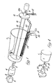
- a minerals separator has a hollow body 1, shown as if transparent, whose inside surface is a frustum.
- the body 1 is open at its wider end and mounted axially at its narrower end on a shaft 2.
- the shaft 2 is reciprocated at 7 Hz, amplitude 11 ⁇ 2 cm each side of rest, by a shaker 3 and rotated at 400 rpm by a motor 4.
- the body 1 has a frustum cone half-angle of 1°, an axial length of 30 cm and an average internal diameter of 30 cm. Larger cone angles are effective at higher rotational speeds.
- the slurry in this example comprises ground ore containing small amounts of valuable (high S.G.) material, the remainder (low S.G. material) being waste, with all particles finer than 75 microns, half finer than 25 microns and quarter finer than 10 microns, this ground ore being suspended at a concentration of 50 to 300g, e.g. 150g, per litre of water.
- the solids feed rate is kept at about 50 to 300g/min, whatever the concentration of solids in the slurry.
- the slurry is fed at 11/min to the narrower end of the hollow body 1 through a slurry feed pipe 16, and the wash water is fed through a pipe 15 slightly to the rear i.e. such that a slurry particle deposited into the body receives wash water a moment later.
- slurry can be fed over an arc of up to say 180° of the body.
- the wash water can likewise be fed over an arc.
- On the other side of the pipe 16 from the pipe 15 is a long generally axial scraper brush 20, which can remove matter from the whole of the inside surface of the body 1 to a collector schematically shown at 21.
- the pipes 15 and 16 and the brushes 20 and 24 are all part of the assembly 10.
- the shorter brush 24 can remove matter from the area which it sweeps, into a collector 25.
- the brushes 20 and 24 are suitably 90° apart (though illustrated closer, for clarity).
- the collectors 21 and 25 cannot be gravity-fed cups as they are shown for simplicity. since the whole assembly 10 is rotating.
- the collectors 21 and 25 could however be annular troughs disposed round the periphery of the open wider end of the hollow body 1, or otherwise adapted to collect (separately, from the brushes 20 and 24) material thrown out centrifugally from the body 1.
- slurry is fed through the pipe 16 to the narrower end of the axially-shaking fast-rotating body 1. Because the body rotates anticlockwise as drawn at 400 rpm while the assembly 10 rotates in the same sense at 399.6 rpm, the net effect is equivalent to a rotation of the assembly clockwise at 0.4 rpm inside the body 1.
- the slurry thus is shaken (by the shaker 3) while subject to several g of centrifugal force (instead of a mere 1g of Earth's gravity) and separates into components of which the lightest move the most rapidly towards the wider end of the body 1. Increasing the shake speed had the effect of making even the denser particles more mobile.
- the shafts 2 and 11 may be driven from the same motor (instead of the separate motors described), with the shaft 11 being nonshaken and powered through a gearbox arranged for a small (e.g. 0.1%) rotational speed differential between the body 1 and the assembly 10). Whether the body or the assembly rotates the faster is an arbitrary matter of choice as long as the assembly is arranged to deliver slurry and to collect, separately, differentiated bands of slurry.
- the separately collected bands of slurry may be further separated in similar or identical separators.
- the similar or identical separators may be mounted on the same shaft, spaced axially, or nested radially outwards, or staggered (nested and slightly axially offset), or any combination of these.
- a minerals separator shown in perspective has a hollow body 201, shown as if transparent, whose inside surface is a frustum.
- the body 201 is open for exit of fluid at both ends and mounted axially at its wider end (by means omitted for clarity), on a shaft indicated at 202.
- the shaft 202 is reciprocated at 7 Hz, amplitude 11 ⁇ 2 cm each side of rest, by a shaker applying the motion 203 and rotated by a motor at 200 rpm in the sense 204.
- the motor is connected via sliding bearings to the shaft 202.
- the shaker acts evenly in each direction (sinusoidally), but shakers acting with a stronger impulse in one direction could be used.
- the shaft 202 is horizontal.
- the body 201 has a frustum cone half-angle of 1°, an axial length of 60 cm and an average internal diameter of 50 cm. Larger cone angles are effective at higher rotational speeds.
- Protruding into the body 201 through its open narrower end is an assembly 210 of accelerator rings 211 and 212 and scraper vanes 213.
- the whole assembly 210 is mounted on a shaft 202a driven through a gearbox by the shaft 202 and rotates together, with the same shake and in the same sense as the rotation of the shaft 202, but at 192 rpm.
- the rings 211 and 212 are fed by stationary pipes with slurry A and wash water B respectively.
- the rings 211 and 212 impart a rotational speed to the slurry and water, which flow through perforations in the rings into the body at substantially the latter's rotational speed and well distributed circumferentially.
- the slurry in this example comprises ground ore from a classifier, containing small amounts of valuable (high S.G.) (usually small-sized) material, the remainder (low S.G. material) (usually larger-sized) being waste, with all particles finer than 75 microns, half finer than 25 microns and quarter finer than 10 microns, this ground ore being suspended at a concentration of 50 to 500g, e.g. 300g, per litre of water.
- the solids feed rate is kept at about 300g/min, whatever the concentration of solids in the slurry.
- the slurry is fed at 11/min to the ring 211 situated around the midpoint of the hollow body 201, and the wash water is fed at 1 ⁇ 21/min to the ring 212 situated at the narrower end of the body 201.
- the vanes 213 are mounted on four equally spaced axial arms (only two shown) each carrying ten resiliently mounted soft plastics vanes 41 ⁇ 2cm long lightly touching the body 201 and angled at 30° to the circumferential direction of the body (recalling that the body 201 is rotating 8 rpm faster than the assembly 210 carrying the arms and vanes) so that matter in the body is forced towards the narrower end.
- the vanes on each arm are staggered with respect to the next arm, overlapping by about 1 ⁇ 2cm, to maximise this effect.
- the slurry A is fed via the accelerator ring 211 to the midpoint of the axially-shaking fast-rotating body 201. Because the body rotates anticlockwise as drawn at 200 rpm while the assembly 210 rotates in the same sense at 192 rpm. the net effect is equivalent to a rotation of the assembly clockwise at 8 rpm inside the body 201.
- the slurry thus is sheared (by the motion 203) while subject to several g of centrifugal force (instead of a mere 1g of Earth's gravity) and separates into components of which the lightest tend to move faster towards the wider end of the body 201. Increasing the shake speed had the effect of making even the denser particles more mobile, but these normally tend to be pinned centrifugally to the body 201.
- the vanes 213 disturb both the denser sessile particles and move them a few centimetres towards the narrower end of the body 201.
- the fluid and the lighter particles levitated by the shake/shear action being more mobile, can continue to flow, past the advancing vane, towards the wider end, helped by the flow of wash water B.
- the denser particles will tend to 'stay put' while the water and the lighter particles will resume their motion towards the wide end of the body 201.
- the denser particles can be considered as being steadily swept, in many short stages, contrary to the axial force, towards the narrower end of the body 201, while the water and the lighter particles can be considered to make their way under the influence of the axial force induced by the taper of the cylinder despite the vanes towards the wider end of the body.
- the matter is thus sorted into valuable high density material C collected at the narrower end and low density waste D collected separately at the wider end.
- the low density material is valuable, perhaps even more valuable than the high density material, but it would still be separated in exactly the same way.
- the shaft 202 and assembly 210 may be driven from separate motors (instead of the same motor described). Whether the body 201 or the assembly 210 rotates the faster is an arbitrary matter of choice as long as the vanes 213 are angled to direct matter pinned to the body generally towards the narrower end of the body 201.
- the separately collected fractions of the slurry may be further separated in similar or identical separators.
- the similar or identical separators may be mounted on the same shaft, spaced axially, or nested radially outwards, or staggered (nested and slightly axially offset), or any combination of these.
- a minerals separator has a hollow body 301, shown as if transparent, whose inner surface is a frustum.
- the body 301 is open at both ends for exit of fluid and is mounted axially at its narrower end, by means omitted for clarity, on a shaft 302, inclined at 2° to 6° (say 2°) to the horizontal (greatly exaggerated in the Figure).
- the wider end of the frustum faces upwardly, even its lowest generator running upwardly, at an inclination of 1°, from narrower to wider end, this inclination thus opposing the axial force induced by the taper itself.
- the half-angle of the frustum is 1°.
- An asymmetrically acting axial shaker 303 shakes the frustum through the shaft 302, with a sharper upward and gentler downward action.
- a particle on the surface of the frustum thus tends to stay still in space, by inertia, during the sharp upward stroke, but during the gentle downward stroke the particle tends to be held frictionally on, and thus to move as one with, the frustum.
- Continued asymmetric shaking in this fashion will thus tend to move such a particle progressively towards the narrower end of the frustum.
- the frustum is rotated on its axis in the sense 304.
- Slurry A is continuously applied near the middle of the frustum and wash water B is continuously applied at an axially similar but circumferentially displaced location.
- the slurry forms a film held centrifugally to the frustum but the axial shaking is sufficient to keep some of its constituents in suspension. Those constituents are not otherwise affected by the shaking.
- the denser constituents are however not kept in suspension and tend to be pinned centrifugally to the frustum subject to the asymmetric shaking action just described, tending to move them to overflow as a heavy-fraction stream C at the narrower end.
- Figure 4 shows a drive system for the minerals separator, providing an alternative to shaking the shaft 2 of Figure 1 and correspond:ng shafts of other Figures; a different perturbation is applied to the body 1 but the separation proceeds otherwise identically as described in relation to Figure 1.
- the body 1 is mounted on a half-shaft 20 of an automotive-type differential unit 21.
- the other half-shaft 22 is powered by the motor 4, which is assisted by a flywheel.
- the 'propeller shaft' 23 is a shaft which is oscillated.
- the oscillations add accelerations and decelerations to the rotation supplied via the half-shaft 22 and reversed by the differential unit 21, in other words the body 1 may be regarded as rotating steadily with superimposed circumferential oscillations.
- a hollow vertical-axis cylinder 31 is set spinning about its axis.
- the internal diameter being 0.3 to 3.0m and the speed of rotation being a modest 50 to 100 rpm, a centrifugal force of the order of 10g radially outwardly is experienced at the internal surface. This is small enough to allow the Earth's g to have significant effect.
- the cylinder 31 is also subjected to circumferential vibration at 5 to 10Hz.
- the cylinder 31 is formed with an inwardly curved lip 32, of radial extent 1 to 10mm. The lip could alternatively be a sharp flange, at 90° or otherwise to the cylinder wall.
- the lower edge may be 1 to 10mm radially inwards of the upper edge, the intervening cylinder wall being straight (i.e. tapered), curved (e.g. parabolic) or partly both, formed for example by centrifugally casting polymer resin.
- a feed pipe 33 supplies slurry containing 100g solids suspended per litre of water to approximately the midpoint (axially) of the cylinder 31.
- the solids are of the size distribution referred to earlier.
- a feed pipe 34 supplies washing water to the internal surface of the cylinder, about mid-way (axially) between the feed pipe 33 and the lip 32.
- a film of slurry is held centrifugally to the internal surface of the cylinder 31 and kept in suspension by the vibration.
- the denser (i.e. higher specific gravity) particles in the slurry tend to move preferentially radially outwardly (centrifugally) and to move downwardly in the boundary layer (under Earth's gravity).
- the vibration which is circumferential e.g. by the means of Figure 4, has a shearing action tending to lift the lower-specific-gravity particles radially inwardly.
- the lip 32 promotes, at the radially inner surface, an upwardly acting hydrodynamic pressure gradient, which thus tends to carry the lower-specific-gravity particles (waste) with the bulk of the fluid flow.
- the lip 32 arrests the heavier particles into a band 35 on their downwards travel, thus both promoting the aforesaid pressure gradient and causing the higher-specific-gravity particles to overflow the lip 32 only after some recirculation and re-sorting (assisted by the vibration).
- the action of the washing water from the pipe 34 is to displace waste accidentally entrained with the higher-specific-gravity particles.
Claims (29)
- Séparateur de minerais comprenant un corps (1,201,301) ayant une surface ayant la forme de l'intérieur d'un cylindre agencé pour que, lorsqu'il tourne autour de son axe (2), une force agisse axialement sur la matière sur ladite surface, des moyens (4) pour faire tourner le corps (1,201,301) autour de l'axe du cylindre pour exercer une force centrifuge supérieure à g sur la matière sur cette surface, des moyens (3,203,303) pour appliquer des perturbations sur le corps, des moyens (16,211,33) pour amener une boue de minerai à séparer, des moyens (15,212,34) pour amener du liquide de lavage dans l'intérieur du cylindre, et des moyens (24,25,etc.) pour recueillir séparément des fractions en provenance d'emplacements différents espacés axialement le long du cylindre, caractérisé en ce qu'il comprend un ensemble (10,210) agencé pour tourner à l'intérieur du cylindre à une vitesse par rapport au cylindre qui est faible par comparaison avec la vitesse de rotation du corps, l'ensemble (10,210) étant également sujet aux perturbations, l'ensemble (10,210) comprenant des moyens d'aubes (213) pour diriger axialement la matière tenue par la force centrifuge sur le corps, en sens contraire de cette force axiale, par pas répétés, chaque pas étant petit par rapport à la longueur axiale du cylindre.
- Séparateur de minerais selon la revendication 1, dans lequel le cylindre est un cylindre droit, ou un tronc de cône, ou est autrement effilé.
- Séparateur de minerais selon la revendication 2, dans lequel le cylindre est un tronc de cône dont le demi-angle au sommet peut atteindre 45°.
- Séparateur de minerais selon la revendication 3, dans lequel le demi-angle au sommet du tronc de cône est compris entre 1/2 et 10°.
- Séparateur de minerais selon la revendication 4, dans lequel le demi-angle au sommet du tronc de cône est 1/2 à 2°.
- Séparateur de minerais selon l'une des revendications précédentes, dans lequel les perturbations sont appliquées par des moyens (3,203,303) impartissant une variation cyclique de la vitesse de rotation du corps.
- Séparateur de minerais selon l'une des revendications 1 à 5, comprenant en outre un dispositif à secousses (3,203,303) agissant dans les deux sens selon l'axe de rotation du corps afin d'appliquer les perturbations.
- Séparateur de minerais selon la revendication 7, dans lequel le dispositif à secousses (3,203,303) agit asymétriquement, de telle sorte que les particules touchant le cylindre tendent à être transportées à l'encontre de cette force axiale.
- Séparateur de minerais selon l'une des revendications précédentes, dans lequel l'axe de rotation est horizontal.
- Séparateur de minerais selon l'une des revendications 1 à 8, dans lequel l'axe de rotation peut faire jusqu'à 45° par rapport à l'horizontale.
- Séparateur de minerais selon la revendication 10, lorsque celle-ci dépend directement ou indirectement des revendications 3, 4 ou 5, dans lequel la génératrice la plus basse du tronc de cône est orientée vers le haut depuis l'extrémité étroite jusqu'à l'extrémité plus large en faisant un angle de 1/4 à 20° par rapport à l'horizontale.
- Séparateur de minerais selon la revendication 11, dans lequel cette inclinaison est comprise entre 1/2 et 6°.
- Séparateur de minerais selon l'une des revendications précédentes, dans lequel au moins certains des moyens pour amener la boue et le liquide de lavage sont montés sur l'ensemble (10,210).
- Séparateur de minerais selon l'une des revendications précédentes, dans lequel les aubes (213) dirigent la matière vers l'extrémité la plus étroite du cylindre.
- Séparateur de minerais selon l'une des revendications précédentes, dans lequel les différents emplacements axialement espacés le long du cylindre sont ses extrémités opposées.
- Séparateur de minerais selon l'une des revendications précédentes, dans lequel les moyens pour faire tourner le cylindre sont un arbre entraîné par un moteur (2), sur lequel sont montés plusieurs cylindres à faible conicité.
- Procédé pour séparer des minerais au moyen du séparateur selon la revendication 1, comprenant les stades suivants : amener une boue contenant le minerai sur la surface intérieure d'un cylindre tournant pour exercer une force centrifuge supérieure à g sur la boue sur la surface, perturber la surface en rotation, disposer la surface pour qu'une force agisse axialement le long de la surface sur la boue, et recueillir de façon continue séparément des fractions de boue en fonction de leurs différents déplacements axialement le long du cylindre, dans lequel la séparation est facilitée par des aubes (213) qui dirigent le contenu du cylindre, par pas répétés, chaque pas étant petit par comparaison avec la longueur axiale du cylindre, dans la direction opposée à celle que tend à prendre la fraction la moins dense sous l'influence de cette force axiale, les aubes (213) et le dispositif d'amenée de la boue étant agencés pour tourner avec le cylindre à une vitesse de rotation différente de la vitesse de rotation du cylindre, mais n'en différant pas de plus de 5%.
- Procédé selon la revendication 17, dans lequel la force agissant axialement le long du cylindre est un gradient de pression hydrodynamique.
- Procédé selon la revendication 18, dans lequel la force agissant axialement le long du cylindre est causée par la conicité du cylindre.
- Procédé selon l'une des revendications 17, 18 ou 19, dans lequel la vitesse de rotation du cylindre est telle que la force centrifuge appliquée sur la surface est comprise entre 5 g et 500 g.
- Procédé selon l'une des revendications 17 à 20, dans lequel le liquide de lavage est amené par intermittence ou de façon continue dans le cylindre à un emplacement tel que ladite force tende à le transporter au droit du point d'amenée de la boue.
- Procédé selon l'une des revendications 17 à 20, dans lequel les conditions de rotation sont telles en ce qui concerne les composants de la boue que la fraction la plus dense est maintenue par la force centrifuge relativement immobile sur le cylindre, tandis que la fraction moins dense s'en sépare axialement, permettant de les recueillir à des emplacements séparés.
- Procédé selon l'une des revendications 17 à 22, dans lequel la perturbation est appliquée en secouant asymétriquement le cylindre dans les deux sens le long de son axe de rotation (2).
- Procédé selon la revendication 23, dans lequel le secouement est asymétrique, de telle sorte que les particules touchant le cylindre tendent à être transportées à l'encontre de cette force axiale.
- Procédé selon l'une des revendications 17 à 24, dans lequel les collectes séparées sont au nombre de deux, une pour chaque extrémité du cylindre.
- Procédé selon l'une des revendications 17 à 25, dans lequel l'axe de rotation du cylindre est horizontal.
- Procédé selon l'une des revendications 17 à 25, dans lequel l'axe de rotation du cylindre peut faire un angle atteignant 45° avec l'horizontale.
- Procédé selon la revendication 27, quand le cylindre est un tronc de cône, dans lequel la génératrice inférieure du tronc de cône est orientée vers le haut depuis l'extrémité étroite jusqu'à l'extrémité plus large en étant inclinée de 1/4 à 20° sur l'horizontale.
- Procédé selon la revendication 28, dans lequel cette inclinaison est comprise entre 1/2 et 6°.
Applications Claiming Priority (2)
| Application Number | Priority Date | Filing Date | Title |
|---|---|---|---|
| GB868612498A GB8612498D0 (en) | 1986-05-22 | 1986-05-22 | Minerals separator |
| GB8612498 | 1986-05-22 |
Related Child Applications (4)
| Application Number | Title | Priority Date | Filing Date |
|---|---|---|---|
| EP19900200821 Division EP0384546A3 (fr) | 1986-05-22 | 1987-05-21 | Séparateur de minerais |
| EP19890200433 Division EP0323447A3 (fr) | 1986-05-22 | 1987-05-21 | Séparateur pour minerais |
| EP89200433.4 Division-Into | 1989-02-22 | ||
| EP90200821.8 Division-Into | 1990-04-05 |
Publications (3)
| Publication Number | Publication Date |
|---|---|
| EP0247795A2 EP0247795A2 (fr) | 1987-12-02 |
| EP0247795A3 EP0247795A3 (en) | 1990-01-17 |
| EP0247795B1 true EP0247795B1 (fr) | 1993-07-21 |
Family
ID=10598290
Family Applications (2)
| Application Number | Title | Priority Date | Filing Date |
|---|---|---|---|
| EP19900200821 Withdrawn EP0384546A3 (fr) | 1986-05-22 | 1987-05-21 | Séparateur de minerais |
| EP87304522A Expired - Lifetime EP0247795B1 (fr) | 1986-05-22 | 1987-05-21 | Séparateur pour minerais |
Family Applications Before (1)
| Application Number | Title | Priority Date | Filing Date |
|---|---|---|---|
| EP19900200821 Withdrawn EP0384546A3 (fr) | 1986-05-22 | 1987-05-21 | Séparateur de minerais |
Country Status (9)
| Country | Link |
|---|---|
| US (2) | US4799920A (fr) |
| EP (2) | EP0384546A3 (fr) |
| JP (2) | JPS62289246A (fr) |
| CN (2) | CN1006446B (fr) |
| AU (2) | AU589091B2 (fr) |
| CA (1) | CA1280384C (fr) |
| DE (1) | DE3786603T2 (fr) |
| GB (2) | GB8612498D0 (fr) |
| ZA (1) | ZA873271B (fr) |
Families Citing this family (20)
| Publication number | Priority date | Publication date | Assignee | Title |
|---|---|---|---|---|
| CH687858A5 (de) * | 1992-07-01 | 1997-03-14 | Fischer Georg Giessereianlagen | Einrichtung zur Regenerierung von Giesserei-Sand. |
| SE9303256D0 (sv) * | 1993-10-05 | 1993-10-05 | Wilje Oscar | Metod / användning / komposition vid materialtvättning |
| JP3710333B2 (ja) * | 1999-07-29 | 2005-10-26 | ホソカワミクロン株式会社 | 気流乾燥装置 |
| CN100569380C (zh) * | 2007-02-08 | 2009-12-16 | 中国矿业大学 | 变径水介质分选装置 |
| JP4910783B2 (ja) * | 2007-03-02 | 2012-04-04 | 栗田工業株式会社 | 製鉄ダスト含有スラリーの遠心分離方法 |
| US7833303B1 (en) | 2007-08-08 | 2010-11-16 | Charles George Higgins | Sifting apparatus with filter rotation and particle collection |
| CN101274300B (zh) * | 2008-03-14 | 2011-02-09 | 株洲市兴民科技有限公司 | 一种细粒物料的选矿方法及装置 |
| CN101961672B (zh) * | 2010-09-16 | 2013-09-25 | 孙文广 | 流体差速分离机 |
| EP3009417A1 (fr) * | 2014-10-13 | 2016-04-20 | LANXESS Deutschland GmbH | Procédé amélioré destiné à fabrication du para-thymol |
| RU2645027C2 (ru) * | 2016-03-22 | 2018-02-15 | Григорий Григорьевич Михайленко | Планетарный сепаратор для разделения минеральных частиц по плотности "вектор-м" |
| RU2632789C1 (ru) * | 2016-04-11 | 2017-10-09 | Григорий Григорьевич Михайленко | Планетарный классифицирующий обогатительный аппарат "грань-м" |
| RU2645021C2 (ru) * | 2016-07-19 | 2018-02-15 | Григорий Григорьевич Михайленко | Центробежный концентратор "сфера-м" |
| RU2648759C1 (ru) * | 2016-11-14 | 2018-03-28 | Григорий Григорьевич Михайленко | Способ центробежного разделения смесей и устройство для его осуществления |
| RU2676111C1 (ru) * | 2017-12-25 | 2018-12-26 | Григорий Григорьевич Михайленко | Способ центробежного разделения смесей |
| CA3096047A1 (fr) | 2018-04-04 | 2019-10-10 | Jody G. Robbins | Separation de mineraux par densite relative |
| CN108722657B (zh) * | 2018-05-31 | 2020-11-03 | 中山大学 | 一种极细颗粒泥沙的分选装置及其使用方法 |
| RU2707111C1 (ru) * | 2019-06-24 | 2019-11-22 | Григорий Григорьевич Михайленко | Прецессионный центробежный концентратор |
| CN110339952B (zh) * | 2019-07-01 | 2021-09-21 | 王秀红 | 一种带有排污装置的工业脱水机 |
| DK180398B1 (en) | 2019-11-13 | 2021-03-25 | Smidth As F L | Centrifugal separator having an improved flow and system comprising such a centrifugal separator |
| RU2760664C1 (ru) * | 2020-12-14 | 2021-11-29 | Григорий Григорьевич Михайленко | Прецессионный центробежный концентратор |
Family Cites Families (44)
| Publication number | Priority date | Publication date | Assignee | Title |
|---|---|---|---|---|
| US287840A (en) * | 1883-11-06 | Ore-concentrator | ||
| DE221255C (fr) * | ||||
| US436133A (en) * | 1890-09-09 | Strom | ||
| US499344A (en) * | 1893-06-13 | centrifugal ore separator | ||
| US2184598A (en) * | 1939-12-26 | G jahn | ||
| US675798A (en) * | 1900-07-23 | 1901-06-04 | Charles F Dubose | Scraper for mixing-machines. |
| US969016A (en) * | 1908-02-13 | 1910-08-30 | Joseph Willmann | Ice-cream freezer. |
| US1080053A (en) * | 1912-04-15 | 1913-12-02 | John S Finlay | Concentrator. |
| US1608767A (en) * | 1920-06-11 | 1926-11-30 | Texas Co | Scraper for stills |
| GB217264A (en) * | 1923-10-20 | 1924-06-19 | Lilleshall Company Ltd | A new or improved centrifugal filter or separator |
| GB335469A (en) * | 1929-12-16 | 1930-09-25 | Elmore Guy Hartwell | Centrifugal driers |
| US2047317A (en) * | 1934-07-16 | 1936-07-14 | Esslen Eugen | Powder mixing device |
| US2243384A (en) * | 1938-10-19 | 1941-05-27 | Kemiska Patenter Ab | Apparatus for mixing and granulating substantially plastic materials |
| US2510057A (en) * | 1944-04-24 | 1950-06-06 | Inst Divi Thomae Foundation | Evaporator |
| US2424367A (en) * | 1945-03-05 | 1947-07-22 | Geo G Titzell Jr | Reciprocating and rotating drum concentrator |
| US2472093A (en) * | 1946-01-16 | 1949-06-07 | Charles E Cournoyer | Cleaning tool for tubes |
| US2653724A (en) * | 1951-02-14 | 1953-09-29 | Richard A Mcbride | Self-unloading truck body |
| GB698750A (en) * | 1951-03-28 | 1953-10-21 | Ottmar Von Loessl | Improvements in and relating to continuously operated centrifuges |
| FR1114535A (fr) * | 1954-11-09 | 1956-04-13 | Perfectionnements aux appareils centrifuges pour la séparation de solides contenus dans un liquide | |
| DE1026693B (de) * | 1954-11-30 | 1958-03-20 | Eisen & Stahlind Ag | Zentrifuge mit spiralfoermigen, im gleichen Winkelabstand voneinander angeordneten Einsaetzen |
| FR1252022A (fr) * | 1957-12-13 | 1961-01-27 | Mobile Mineral Extractions Pty | Concentreur à gravité |
| DE1020930B (de) * | 1958-11-13 | 1957-12-12 | Siebtechnik G.m.b.H., Mülheim/Ruhr-Speldorf | Schwingzentrifuge |
| US3235173A (en) * | 1960-07-28 | 1966-02-15 | Unger Hans Peter Olof | Agitating and/or fractioning centrifuge |
| US3161581A (en) * | 1960-08-24 | 1964-12-15 | Exxon Research Engineering Co | Centrifugal processing of tar sands |
| US3181840A (en) * | 1962-04-12 | 1965-05-04 | Rietz Mfg Co | Mixing apparatus |
| US3145017A (en) * | 1962-06-06 | 1964-08-18 | Gen Equipment Mfg And Sales In | Agitator-for dispensing freezer |
| US3271572A (en) * | 1962-08-24 | 1966-09-06 | Unit Process Assemblies | Direct reading beta ray comparator |
| US3298679A (en) * | 1964-04-29 | 1967-01-17 | Harbison Walker Refractories | Rotary kiln scraper |
| US3446666A (en) * | 1966-08-29 | 1969-05-27 | Albert G Bodine | Sonic process and apparatus for cleaning pipes |
| GB1215716A (en) * | 1967-05-02 | 1970-12-16 | Broadbent & Sons Ltd Thomas | Improvements in or relating to vibrating centrifuges |
| US3754660A (en) * | 1971-07-28 | 1973-08-28 | H Cottrell | Apparatus for extracting fluid from pulp |
| US3731339A (en) * | 1971-09-29 | 1973-05-08 | Sun Oil Co Pennsylvania | Scraper assembly for process vessels |
| JPS5021514B2 (fr) * | 1972-04-12 | 1975-07-23 | ||
| JPS4922654A (fr) * | 1972-06-27 | 1974-02-28 | ||
| GB1516135A (en) * | 1975-05-23 | 1978-06-28 | Cross D | Mineral jigs |
| SU724193A1 (ru) * | 1976-11-26 | 1980-03-30 | Новосибирский инженерно-строительный институт им.В.В.Куйбышева | Промывочна машина |
| GB1576469A (en) * | 1977-03-25 | 1980-10-08 | Nat Res Dev | Sand separator |
| CH623487A5 (fr) * | 1977-09-06 | 1981-06-15 | Erich Kaelin | |
| JPS5451068A (en) * | 1977-09-29 | 1979-04-21 | Kazue Tanaka | Automatic changeover apparatus for injection and suspension of low liquid in centrifugal separator |
| US4218323A (en) * | 1978-08-09 | 1980-08-19 | Gala Industries, Inc. | Pellet free rotor for centrifugal pellet dryers |
| US4286748A (en) * | 1980-05-19 | 1981-09-01 | Bailey Albert C | Centrifugal concentrator |
| US4361480A (en) * | 1981-07-29 | 1982-11-30 | Corbus Henry F | Separator unit for gold mining assembly |
| DE3309385A1 (de) * | 1983-03-16 | 1984-09-20 | Klöckner-Humboldt-Deutz AG, 5000 Köln | Verfahren und vorrichtung zur nassmechanischen sortierung von feinkoernigen, mineralischen rohstoffen |
| US4608040A (en) * | 1983-07-05 | 1986-08-26 | Knelson Benjamin V | Centrifugal separator |
-
1986
- 1986-05-22 GB GB868612498A patent/GB8612498D0/en active Pending
-
1987
- 1987-05-07 ZA ZA873271A patent/ZA873271B/xx unknown
- 1987-05-20 US US07/051,648 patent/US4799920A/en not_active Expired - Lifetime
- 1987-05-21 EP EP19900200821 patent/EP0384546A3/fr not_active Withdrawn
- 1987-05-21 CA CA000537641A patent/CA1280384C/fr not_active Expired - Lifetime
- 1987-05-21 JP JP62124996A patent/JPS62289246A/ja active Granted
- 1987-05-21 EP EP87304522A patent/EP0247795B1/fr not_active Expired - Lifetime
- 1987-05-21 GB GB8712031A patent/GB2190609B/en not_active Expired - Lifetime
- 1987-05-21 DE DE87304522T patent/DE3786603T2/de not_active Expired - Lifetime
- 1987-05-22 AU AU73301/87A patent/AU589091B2/en not_active Expired
- 1987-05-22 CN CN87103807A patent/CN1006446B/zh not_active Expired
-
1989
- 1989-01-10 US US07/295,346 patent/US4964845A/en not_active Expired - Lifetime
- 1989-03-14 CN CN89101493A patent/CN1036148A/zh active Pending
- 1989-03-29 AU AU31790/89A patent/AU602445B2/en not_active Ceased
- 1989-05-16 JP JP1122675A patent/JPH0271860A/ja active Pending
Also Published As
| Publication number | Publication date |
|---|---|
| EP0384546A2 (fr) | 1990-08-29 |
| EP0247795A2 (fr) | 1987-12-02 |
| EP0384546A3 (fr) | 1990-10-17 |
| JPS62289246A (ja) | 1987-12-16 |
| CN87103807A (zh) | 1987-12-02 |
| US4964845A (en) | 1990-10-23 |
| AU3179089A (en) | 1989-07-20 |
| AU589091B2 (en) | 1989-09-28 |
| AU7330187A (en) | 1987-11-26 |
| DE3786603T2 (de) | 1993-10-28 |
| CA1280384C (fr) | 1991-02-19 |
| CN1006446B (zh) | 1990-01-17 |
| GB2190609A (en) | 1987-11-25 |
| EP0247795A3 (en) | 1990-01-17 |
| JPH0335981B2 (fr) | 1991-05-30 |
| GB8712031D0 (en) | 1987-06-24 |
| AU602445B2 (en) | 1990-10-11 |
| DE3786603D1 (de) | 1993-08-26 |
| US4799920A (en) | 1989-01-24 |
| JPH0271860A (ja) | 1990-03-12 |
| CN1036148A (zh) | 1989-10-11 |
| GB2190609B (en) | 1991-01-09 |
| GB8612498D0 (en) | 1986-07-02 |
| ZA873271B (en) | 1989-01-25 |
Similar Documents
| Publication | Publication Date | Title |
|---|---|---|
| EP0247795B1 (fr) | Séparateur pour minerais | |
| EP0275159B1 (fr) | Appareil centrifuge de concentration | |
| CA2097313C (fr) | Crible rotatif | |
| CA1285907C (fr) | Separateur de matieres minerales | |
| EP0348213A2 (fr) | Séparateur de solides de liquides | |
| GB2211442A (en) | Minerals separator | |
| EP0323447A2 (fr) | Séparateur pour minerais | |
| US3276591A (en) | Apparatus for treating suspensions | |
| EP0072820A4 (fr) | Appareil de separation des particules d'une boue. | |
| EP0258012A2 (fr) | Séparateur centrifuge solides-liquides | |
| SU1050757A1 (ru) | Устройство дл выделени твердых частиц из суспензий | |
| SU452363A1 (ru) | Устройство дл разделени суспензии в тонкой пленке | |
| JPH07860A (ja) | 連続固液分離方法、及びこれを用いた連続固液分離装置 | |
| US3400827A (en) | Liquid and chip separator | |
| RU2114699C1 (ru) | Центробежный сепаратор | |
| SU957966A1 (ru) | Центробежно-вибрационный концентратор | |
| EP0002125A1 (fr) | Centrifugeuse et méthode de séparation de matériaux | |
| GB2046632A (en) | The Recovery of Hydrophobic Particles | |
| SU844065A1 (ru) | Способ разделени суспензии твердогоМЕлКОзЕРНиСТОгО МАТЕРиАлА пО плОТНОСТиВ жидКОСТи и цЕНТРифугА дл ЕгО ОСущЕСТВлЕНи | |
| JPH0636885B2 (ja) | 振動式固液分離機 | |
| GB2177624A (en) | Separating or cleaning particulate material | |
| JPS6130604B2 (fr) | ||
| AU8141982A (en) | Apparatus for the separation of particles from a slurry |
Legal Events
| Date | Code | Title | Description |
|---|---|---|---|
| PUAI | Public reference made under article 153(3) epc to a published international application that has entered the european phase |
Free format text: ORIGINAL CODE: 0009012 |
|
| AK | Designated contracting states |
Kind code of ref document: A2 Designated state(s): DE FR GB IT SE |
|
| 17P | Request for examination filed |
Effective date: 19880307 |
|
| PUAL | Search report despatched |
Free format text: ORIGINAL CODE: 0009013 |
|
| AK | Designated contracting states |
Kind code of ref document: A3 Designated state(s): DE FR GB IT SE |
|
| 17Q | First examination report despatched |
Effective date: 19911212 |
|
| RAP1 | Party data changed (applicant data changed or rights of an application transferred) |
Owner name: BRITISH TECHNOLOGY GROUP LTD |
|
| GRAA | (expected) grant |
Free format text: ORIGINAL CODE: 0009210 |
|
| AK | Designated contracting states |
Kind code of ref document: B1 Designated state(s): DE FR GB IT SE |
|
| PG25 | Lapsed in a contracting state [announced via postgrant information from national office to epo] |
Ref country code: IT Free format text: LAPSE BECAUSE OF FAILURE TO SUBMIT A TRANSLATION OF THE DESCRIPTION OR TO PAY THE FEE WITHIN THE PRE;WARNING: LAPSES OF ITALIAN PATENTS WITH EFFECTIVE DATE BEFORE 2007 MAY HAVE OCCURRED AT ANY TIME BEFORE 2007. THE CORRECT EFFECTIVE DATE MAY BE DIFFERENT FROM THE ONE RECORDED.SCRIBED TIME-LIMIT Effective date: 19930721 |
|
| XX | Miscellaneous (additional remarks) |
Free format text: TEILANMELDUNG 89200433.4 EINGEREICHT AM 21/05/87. |
|
| ET | Fr: translation filed | ||
| REF | Corresponds to: |
Ref document number: 3786603 Country of ref document: DE Date of ref document: 19930826 |
|
| PLBE | No opposition filed within time limit |
Free format text: ORIGINAL CODE: 0009261 |
|
| STAA | Information on the status of an ep patent application or granted ep patent |
Free format text: STATUS: NO OPPOSITION FILED WITHIN TIME LIMIT |
|
| 26N | No opposition filed | ||
| EAL | Se: european patent in force in sweden |
Ref document number: 87304522.3 |
|
| REG | Reference to a national code |
Ref country code: GB Ref legal event code: IF02 |
|
| PGFP | Annual fee paid to national office [announced via postgrant information from national office to epo] |
Ref country code: SE Payment date: 20060505 Year of fee payment: 20 |
|
| PGFP | Annual fee paid to national office [announced via postgrant information from national office to epo] |
Ref country code: FR Payment date: 20060515 Year of fee payment: 20 |
|
| PGFP | Annual fee paid to national office [announced via postgrant information from national office to epo] |
Ref country code: GB Payment date: 20060517 Year of fee payment: 20 |
|
| PGFP | Annual fee paid to national office [announced via postgrant information from national office to epo] |
Ref country code: DE Payment date: 20060518 Year of fee payment: 20 |
|
| REG | Reference to a national code |
Ref country code: GB Ref legal event code: PE20 |
|
| EUG | Se: european patent has lapsed | ||
| PG25 | Lapsed in a contracting state [announced via postgrant information from national office to epo] |
Ref country code: GB Free format text: LAPSE BECAUSE OF EXPIRATION OF PROTECTION Effective date: 20070520 |