EP0247767B1 - Verfahren und Vorrichtung zum Steuern der Richtung eines Schlagbohrwerkzeugs im Bohrloch - Google Patents
Verfahren und Vorrichtung zum Steuern der Richtung eines Schlagbohrwerkzeugs im Bohrloch Download PDFInfo
- Publication number
- EP0247767B1 EP0247767B1 EP87304342A EP87304342A EP0247767B1 EP 0247767 B1 EP0247767 B1 EP 0247767B1 EP 87304342 A EP87304342 A EP 87304342A EP 87304342 A EP87304342 A EP 87304342A EP 0247767 B1 EP0247767 B1 EP 0247767B1
- Authority
- EP
- European Patent Office
- Prior art keywords
- tool
- boring
- housing
- hammer
- pipe
- Prior art date
- Legal status (The legal status is an assumption and is not a legal conclusion. Google has not performed a legal analysis and makes no representation as to the accuracy of the status listed.)
- Expired - Lifetime
Links
- 238000005553 drilling Methods 0.000 title claims abstract description 51
- 238000009527 percussion Methods 0.000 title abstract description 6
- 238000000034 method Methods 0.000 title description 11
- 230000033001 locomotion Effects 0.000 claims abstract description 18
- 239000002689 soil Substances 0.000 claims description 9
- 230000001154 acute effect Effects 0.000 claims 1
- 238000007599 discharging Methods 0.000 claims 1
- 230000000149 penetrating effect Effects 0.000 claims 1
- 238000004891 communication Methods 0.000 abstract description 4
- 239000007787 solid Substances 0.000 abstract description 2
- 238000009412 basement excavation Methods 0.000 description 5
- 230000009471 action Effects 0.000 description 4
- 230000008901 benefit Effects 0.000 description 4
- 238000005520 cutting process Methods 0.000 description 4
- 230000007246 mechanism Effects 0.000 description 4
- 230000008859 change Effects 0.000 description 3
- 238000012360 testing method Methods 0.000 description 3
- 238000010276 construction Methods 0.000 description 2
- 238000011161 development Methods 0.000 description 2
- 230000000694 effects Effects 0.000 description 2
- 238000009434 installation Methods 0.000 description 2
- 238000012986 modification Methods 0.000 description 2
- 230000004048 modification Effects 0.000 description 2
- 230000007935 neutral effect Effects 0.000 description 2
- 230000004044 response Effects 0.000 description 2
- 238000012935 Averaging Methods 0.000 description 1
- 230000002411 adverse Effects 0.000 description 1
- 230000005540 biological transmission Effects 0.000 description 1
- 230000015572 biosynthetic process Effects 0.000 description 1
- 238000013461 design Methods 0.000 description 1
- 230000007613 environmental effect Effects 0.000 description 1
- 239000012530 fluid Substances 0.000 description 1
- 230000005484 gravity Effects 0.000 description 1
- 230000001939 inductive effect Effects 0.000 description 1
- 238000012423 maintenance Methods 0.000 description 1
- 231100000989 no adverse effect Toxicity 0.000 description 1
- 230000035515 penetration Effects 0.000 description 1
- 230000008439 repair process Effects 0.000 description 1
- 238000011160 research Methods 0.000 description 1
Images


Classifications
-
- E—FIXED CONSTRUCTIONS
- E21—EARTH OR ROCK DRILLING; MINING
- E21B—EARTH OR ROCK DRILLING; OBTAINING OIL, GAS, WATER, SOLUBLE OR MELTABLE MATERIALS OR A SLURRY OF MINERALS FROM WELLS
- E21B4/00—Drives for drilling, used in the borehole
- E21B4/06—Down-hole impacting means, e.g. hammers
- E21B4/14—Fluid operated hammers
- E21B4/145—Fluid operated hammers of the self propelled-type, e.g. with a reverse mode to retract the device from the hole
-
- E—FIXED CONSTRUCTIONS
- E21—EARTH OR ROCK DRILLING; MINING
- E21B—EARTH OR ROCK DRILLING; OBTAINING OIL, GAS, WATER, SOLUBLE OR MELTABLE MATERIALS OR A SLURRY OF MINERALS FROM WELLS
- E21B7/00—Special methods or apparatus for drilling
- E21B7/04—Directional drilling
- E21B7/06—Deflecting the direction of boreholes
- E21B7/068—Deflecting the direction of boreholes drilled by a down-hole drilling motor
-
- E—FIXED CONSTRUCTIONS
- E21—EARTH OR ROCK DRILLING; MINING
- E21B—EARTH OR ROCK DRILLING; OBTAINING OIL, GAS, WATER, SOLUBLE OR MELTABLE MATERIALS OR A SLURRY OF MINERALS FROM WELLS
- E21B7/00—Special methods or apparatus for drilling
- E21B7/26—Drilling without earth removal, e.g. with self-propelled burrowing devices
Definitions
- This invention relates to new and useful improvements in earth boring tools and more particularly to improved tools for boring more or less horizontally through the earth for laying utility lines, such as gas lines, electrical or communications conduit, etc.
- Utility Companies often find it necessary to install or replace piping beneath different types of surfaces such as streets, driveways, railroad tracks, etc. To reduce costs and public inconvenience by eliminating unnecessary excavation and restoration, utilities sometimes use underground boring tools to install the new or replacement pipes.
- Existing boring tools are suitable for boring short distances (up to 18.3m ), but are not sufficiently advanced to provide directional control for longer distances. This lack of control, coupled with the inability of these tools to detect and steer around obstacles, has limited their use to about 20% of all excavations, with the majority of the remaining excavations being performed by open-cut trenching methods.
- US-A-1 894 446 discloses a device for driving conduit pipes through the ground, in which a tapered driving head is attached to the leading end of the pipe and a pneumatic hammer is applied to the trailing end in a launching pit to drive the pipe forward.
- Conventional pneumatic and hydraulic percussion moles are designed to pierce and compact compressible soils for the installation of underground utilities without the necessity of digging large launching and retrieval pits, open cutting of pavement or reclamation of large areas of land.
- An internal striker or hammer reciprocates under the action of compressed air or hydraulic fluid to deliver high energy blows to the inner face of the body. These blows propel the tool through the soil to form an earthen casing within the soil that remains open to allow laying of cable or conduit.
- Two boring modes could be obtained with this system by changing the position of the rotatable fin relative to the fixed fin. These were (1) a roll mode in which the mole was caused to rotate about its longitudinal centerline as it advanced into the soil and (2) a steering mode in which the mole was directed to bore in a curved path.
- the roll mode was used for both straight boring and as a means for selectively positioning the angular orientation of the fins for subsequent changes in the bore path.
- Rotation of the mole was induced by bringing the rotatable fin into an anti-parallel alignment with the fixed fin. This positioning results in the generation of a force couple which initiates and maintains rotation.
- the steering mode was actuated by locating the rotatable fin parallel to the fixed fin. As the mole penetrates the soil, the outer surfaces of the oncoming fins are brought into contact with the soil and a "slipping wedge” mechanism created. This motion caused the mole to veer in the same direction as the fins point when viewed from the back of the tool.
- Coyne et al, U.S. Patent 3,525,405 discloses a steering system which uses a beveled planar anvil that can be continuously rotated or rigidly locked into a given steering orientation through a clutch assembly.
- Chepurnoi et al, U.S. Patent 3,952,813 discloses an off-axis or eccentric hammer steering system in which the striking position of the hammer is controlled by a transmission and motor assembly.
- Gagen et al, U.S. Patent 3,794,128 discloses a steering system employing one fixed and one rotatable tail fin.
- a steering system for percussion boring tools for boring in the earth at an angle or in a generally horizontal direction.
- the steering mechanism comprises a slanted-face nose member attached to the anvil of the tool to produce a turning force on the tool and movable tail fins incorporated into the trailing end of the tool which are adapted to be selectively positioned relative to the body of the tool to negate the turning force.
- Turning force may also be imparted to the tool by an eccentric hammer which delivers an off-axis impact to the tool anvil.
- the fins are constructed to assume a neutral position relative to the housing of the tool when the tool is allowed to turn and to assume a spin inducing position relative to the housing of the tool to cause it to rotate when the tool is to move in a straight direction.
- the tail fins are fixed to induce spin of the tool about its longitudinal axis to compensate for the turning effect of the slanted nose member or eccentric hammer.
- the slanted nose member or the eccentric hammer will deflect the tool in a given direction.
- the fins also allow the nose piece to be oriented in any given plane for subsequent steering operation.
- One object of this invention to provide a cost-effective guided horizontal boring tool which can be used to produce small diameter boreholes into which utilities, e.g., electric or telephone lines, TV cable, gas distribution piping, or the like, can be installed.
- utilities e.g., electric or telephone lines, TV cable, gas distribution piping, or the like
- Another object of the invention is to provide a steering system that offers a repeatable and useful steering response in boreholes which is compatible with existing boring equipment and methods and requires only minimal modification of existing boring tools.
- Another object of this invention is to provide a steering system which will enable a horizontal boring tool to travel over great distances and reliably hit a small target.
- Another object of this invention is to provide boring tool which will produce a guided borehole to avoid obstacles and to correct for deviations from the planned boring path.
- Another object of this invention is to provide a boring tool immune to adverse environmental conditions and which allows the boring operation to be conducted by typical field service crews.
- a further object of this invention is to provide a guided horizontal boring tool which requires a minimal amount of excavation for launching and retrieval and thereby reducing the disturbance of trees, shrubs or environmentally sensitive ecosystems.
- a further object of this invention is to provide a guided horizontal boring tool which is operated from a rigid external operating member and driven by an external power source.
- a still further object of this invention is to provide a guided horizontal boring tool which is supported on a drill rod or pipe and operated by a drill rig either from a launching pit or from the surface.
- a still further object of this invention is to provide a guided horizontal boring tool operated from a rigid external operating member and driven by an external power source and controlled for direction of movement from outside the borehole.
- a still further object of this invention is to provide a guided horizontal boring tool operated from a rigid external operating member and driven by an external power source and includes an expander boring element driven into the earth by non-rotative movement.
- apparatus for drilling holes in the earth comprising an asymmetric earth boring tool tapering longitudinally towards the end thereof, means for urging the tool into the earth, the tool being mounted on a substantially rigid drill rod or pipe, support means remote from the tool serving to support the drill rod or pipe, said tool having an external surface shaped to cause deflection of the tool and means for selectively rotating the tool , such that when the tool is rotated it moves in a substantially straight line and when the tool is not rotated the external surface of the tool causes it to deflect away from the longitudinal axis of the tool as it is urged into the earth, such that directional control of the tool can be affected, characterised in that the tool is a mole containing percussive drive means, the means for selectively rotating the drill rod, or pipe, comprise said support means remote from the tool serving to selectively rotate the drill rod or pipe and said support means serve to permit addition and removal of the drill rod or pipe during drilling.
- a guided horizontal boring tool constructed in accordance with the present invention will benefit utilities and rate payers by significantly reducing installation and maintenance costs of underground utilities by reducing the use of expensive, open-cut trenching methods.
- Long utility holes, for gas lines, electrical or communications conduit and the like, may be bored or pierced horizontally through the earth, particularly under obstacles, such as buildings, rivers, lakes, etc.
- Such holes may be bored by an underground drilling mole (underground percussion drill) supported on a hollow drill rod and supplied with compressed air through the rod to operate an air hammer which strikes an anvil having an external boring face, preferably constructed to apply an asymmetric boring force, e.g., by (a) a bent sub for a hammer, (b) a deflection pad on a hammer, (c) an asymmetric hammer or (d) a boring member having an inclined plane on the piercing or boring face.
- underground drilling mole underground percussion drill
- an air hammer which strikes an anvil having an external boring face, preferably constructed to apply an asymmetric boring force, e.g., by (a) a bent sub for a hammer, (b) a deflection pad on a hammer, (c) an asymmetric hammer or (d) a boring member having an inclined plane on the piercing or boring face.
- the drill rod is operated by a drill rig on the surface or recessed in special pit for horizontal drilling and provides for addition of sections of pipe or hollow rod as the boring progresses.
- the asymmetric boring force causes the boring path to curve and, when straight line drilling is needed, the drill rod is rotated to counteract the asymmetric boring force.
- An alternative boring tool utilizes an expander supported on a solid or hollow drill rod and having a base end supported on and larger in diameter than the rod and tapering longitudinally forward therefrom to an extension extending a short distance forward. The tool penetrates the earth upon longitudinal movement of the drill rod.
- Fig. 1 is a schematic drawing, partially in section, showing horizontal boring from a recessed pit containing a drilling rig.
- Fig. 2 is a schematic drawing, partially in section, showing horizontal boring from a drilling rig on the surface.
- Fig. 3 is a schematic drawing, partially in section, showing horizontal boring from a recessed pit containing a drilling rig, using a drilling mole mounted on a hollow drill rod or pipe driven by the rig..
- Fig. 5 is a more detailed schematic of the drill rig and drilling mole shown in Fig. 3.
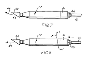
- Figs. 7 and 8 are more detailed schematics of the drilling mole shown in Figs. 3 and 5, illustrating straight line and curved movement of the tool.
- Fig. 13 is a sectional view of the connection sub for mounting the boring mole on the hollow drill rod to provide for exhausting air from the mole.
- Figs. 14A and 14B are longitudinal sections of the front and rear portions of the drilling mole.
- Fig. 15 is a longitudinal section of the front portion of a drilling mole having an eccentric hammer.
- FIG. 1 there are shown schematic views, in vertical section, of two versions of the horizontal boring of long utility holes according to this invention.
- the experimental work done in the development of this invention has shown that it is feasible to bore long horizontal utility holes, from 61 to 610 metres, more economically than trenching or augering.
- Two systems for boring long horizontal utility holes are illustrated in Figs. 1 and 2.
- FIG. 1 there is shown a schematic view of long horizontal boring starting from a launching pit.
- a launching pit P in which there is positioned a drilling rig and boring apparatus generally designated 10 for boring a horizontal hole along the drill line 11 to an exit pit P ⁇ .
- the bore hole 11 is shown extending beneath a plurality of building B.
- Fig. 2 there is shown an alternate version of horizontal boring which uses a slant drilling technique.
- the drill rig 10 is mounted at about a 30 degree angle to the earth so that the boring enters the earth at a 30 ⁇ angle and continues along an arcuate path 12 where it exits from the earth at an exit point 13 beyond the obstacles under which the hole has been drilled.
- the bore hole 12 passes beneath a variety of obstacles generally designated O, including for example, a windmill, a lake or river and a building.
- obstacles generally designated O, including for example, a windmill, a lake or river and a building.
- the utility pipe or conduit laid in the holes which are bored will connect to trenches for continuing the utility lines beyond the obstacles where trenching may be the more economical way to lay pipe or conduit.
- Horizontal holes including both the straight horizontal holes and the slant or arcuate holes have the advantages that the holes require less direction change and are closer to the surface in case the pipe or the downhole motor have to be dug up.
- the straight horizontal holes however, have the disadvantage that a pit has to be dug to hold the boring machine and the work area may be limited.
- the slant holes extend in a generally horizontal direction along an arcuate path but may give rise to problems in the event that the downhole motor is disabled.
- Both the slant boring and the straight horizontal boring are good methods for rapid and inexpensive implacement of utility lines.
- Slant holes are best suited for boring long utility holes, e.g. 150 to 610 metrs , where larger rigs are required.
- Straight horizontal boring is best for shorter holes, e.g. 61 to 152 metres, which require small drill rigs and where slant holes would require rapid angle change in order to maintain a shallow corridor or to hit a small target. Both drilling techniques have been demonstrated in extensive field tests of the apparatus which was developed in accordance with this invention.
- FIGs. 3, 5, 7, 8 and 13 there are shown various aspects of the invention utilizing a drilling mole supported on a hollow drill rod or pipe for a horizontal boring operation.
- FIG. 3 there is shown a launching it P recessed from the surface S of the earth on one side of an obstacle such as a road bed R' under which the utility hole is to be bored.
- a drill rig R is shown schematically in the launching pit P supported on tracks 14.
- the rig R is of a construction similar to vertically operated drilling rigs but utilizes movement along the tracks 14 to provide the drilling thrust.
- Drilling rig R is operable to support and move sections of drill rod 15 and permits the addition of additional sections of rod as the drilling progresses through the earth.
- the drilling rig R is provided with conventional controls illustrated by control handle 16 on the drill console.
- Drill rod 15 supports a drilling mole 17 at its end for drilling a horizontal hole 18 through the earth.
- Drilling mole 17 is a pneumatically operated drilling mole and may have the structure shown in U.S. patent 4 632 191.
- Drill rod 15 is hollow and connected to the source 19 of compressed air. Compressed air from compressed air source 19 is supplied through hollow drill rod 15 to pneumatic mole 17 which operates a hammer (not shown) which pounds on an anvil member connected to an external boring element 20.
- Drilling mole 17 has a connection sub 21 connecting the mole to the hollow drill rod or pipe 15.
- Connection sub 21 is shown in detail in Fig. 13 and has a plurality of holes or openings 22 for exhausting air from mole 17 back into the bore hole 18 behind the mole.
- boring mole 17 operates through boring element 20 to punch or pierce a hole through the earth. This mechanism of boring avoids the formation of cuttings or spoils which must be removed from the bore hole.
- the mole 17 operates strictly by a percussive boring or piercing and not by any rotary boring movement.
- the angled cutting face on boring element 20 causes the boring mole to deviate from a straight path and to follow a continually curving path. This permits the use of a tool for drilling slant holes along an arcuate path as shown in Fig. 2. It also permits the tool to be used where a straight hole needs to be drilled and at some point into the hole the mole is allowed to deviate along a selected curved path to emerge from underground through the surface of the earth.
- the drilling rig R has a mechanism for not only advancing the supporting pipe 15 and drilling mole 17 but also to rotate the pipe and drilling mole. If the drilling rig R causes pipe 15 and drilling mole 17 to rotate the angled boring surface 45 of boring element 20 is rotated and the tool is allowed to move in a straight line. Actually the tool does not move in a perfectly straight line but rather in a very tight spiral which is substantially a straight line.
- the arrangement for providing an asymmetric boring force shown in Fig. 3 may be replaced by an asymmetric hammer in the boring tool as shown in U.S. Patent 4 632 191.
- the details of the asymmetric hammer do not form a part of this invention but merely illustrate another means for applying an asymmetric boring force in the apparatus and method of this invention which involves drilling either straight horizontal bore holes or arcuate bore holes using a drilling mole supported on a hollow pipe or drill rod moved by a drill rig.
- deflecting a drill bit or other earth boring member may be used, such as deflection pads on an in-hole hammer, or a bent sub supporting a in-hole hammer.
- deflection pads on an in-hole hammer or a bent sub supporting a in-hole hammer.
- the means for rotating the hammer or the boring or piercing member may be omitted.
- FIG. 5 there is shown some additional details of this earth boring method and apparatus.
- drill rig R is mounted on track 14 and is provided with a motor 23 for advancing the console 24 of the rig along the track and also for providing the means for rotating the hollow drill rod or pipe 15.
- Console 24 has control handle 16 which determine the advance of the console along track 14 and also may selectively rotate the drill rod 15 or permit the drill rod to remain in a non-rotating position.
- the drill rig R utilizes conventional features of drill rig design for surface rigs which permits the addition of successive sections on drill rod or pipe 15 as the drill mole 17 is moved through the earth.
- the connection 25 is shown on the rear end of drill pipe 15 with conduit or piping 26 extending to the source 19 of compressed air.
- Connecting sub 21 which connects the housing of drilling mole 17 to the hollow drill rod or pipe 15.
- Connecting sub 21 comprises a main tubular body portion 27 having smaller tubular extensions 28 and 29 at opposite ends. Extensions 28 and 29 fit respectively into the open rear end of the housing of drilling mole 17 and the forward end of drill pipe 15.
- the main body portion 17 has an enlarged bore 30 which receives a cylindrical supporting member 31 having a central bore 32 and a plurality of air passages 33.
- Supporting member 31 supports tubular member 34 in the central bore 32.
- Tubular member 34 terminates in a flanged end portion 35 which supports an annular check valve 36 which is normally closed against a valve surface 37.
- Another tubular member 38 is supported in tubular extension 29 and sealed against leakage of air pressure by O-ring 39.
- Tubular member 38 receives the reduced diameter end portion 40 of a tubular member 41 which extends into the housing of mole 17 for conducting air into the mole for operating the hammer.
- This connection sub conducts compressed air from drill rod or pipe 15 through the inlet 42 to tubular member 38 and through the hollow bore 43 of tubular member 41 into the drill motor for operating the hammer which provides a percussive force to the boring element 20.
- the spent air from operating the hammer passes from the housing of mole 17 through passage 44 and passages 33 and supporting member 31, passed check valve 36 and out through the exhaust ports or passages 21.
- Figs. 7 and 8 show the end of drill pipe or rod 15, drilling mole 17, and boring element 20 in the non-rotating position where the operation of the slanted or inclined face 45 of boring element 20 against the earth will cause the tool to deviate in a curved path as shown by the directional arrow 46.
- the apparatus is shown as being rotated as indicated by arrow 47 and moved by linear or longitudinal movement of pipe 15. This causes the tool to bore in a straight line as indicated by directional arrow 48.
- Figs. 14A and 14B are longitudinal sections on the boring mole 17 shown in Figs. 3, 5, 7 and 8.
- boring mole 17 comprises an elongated hollow cylindrical outer housing or body 128.
- the outer front end of the body 128 tapers inwardly forming a conical portion 129.
- the internal diameter of body 128 tapers inwardly near the front end forming a conical surface 130 which terminates in a reduced diameter 131 extending longitudinally inward from the front end.
- the rear end of body 128 has internal threads for receiving connection sub 21.
- An anvil 133 having a conical back portion 134 and an elongated cylindrical front portion 135 is positioned in the front end of body 128.
- Conical back portion 134 of anvil 133 forms an interference fit on conical surface 130 of body 128, and the elongated cylindrical portion 135 extends outwardly a predetermined distance beyond the front end of the body.
- a flat transverse surface 136 at the back end of anvil 133 receives the impact of a reciprocating hammer 137.
- Reciprocating hammer 137 is an elongated cylindrical member slidably received within the cylindrical recess 138 of body 128. A substantial portion of the outer diameter of hammer 128 is smaller in diameter than recess 138 in body 128, forming an annular cavity 139 therebetween. A relatively shorter portion 140 at the back end of the hammer 137 is of larger diameter to provide a sliding fit against the interior wall of recess 138 of the body 128.
- a central cavity 141 extends longitudinally inward from the back end of hammer 137.
- a cylindrical bushing 142 is slidably disposed within hammer cavity 141.
- the front surface 143 of the front end of hammer 137 is shaped to provide an impact centrally on the flat surface 136 of anvil 133.
- the hammer configuration may also be adapted to deliver an eccentric impact force on the anvil.
- An air distribution tube 41 extends centrally through bushing 142 and has its back end connected through connection sub 21 to supporting pipe 15.
- air distribution tube 41 is in permanent communication with a compressed air source through passages 144 and bushing 142 is such that, during reciprocation of hammer 137, air distribution tube 41 alternately connects annular cavity 139 with the central cavity 141 or atmosphere.
- a cylindrical stop member 149 is secured within recess 138 in body 128 near the back end and has a series of longitudinally-extending, circumferentially-spaced passageways 150 for exhausting the interior of body 28 to atmosphere through connection sub 21 and a central passage through which the air distribution tube 41 extends.
- a slant-end nose member 20 has a cylindrically recessed portion 152 with a central cylindrical bore 153 therein which is received on the cylindrical portion 135 of the anvil 133 (Fig. 14A).
- a slot 154 through the sidewall of the cylindrical portion 118 extends longitudinally substantially the length of the central bore 153 and a transverse slot extends radially from the bore 153 to the outer circumference of the cylindrical portion, providing flexibility to the cylindrical portion for clamping the nose member to the anvil.
- a flat 156 is provided on one side of cylindrical portion 118 and longitudinally spaced holes 157 are drilled therethrough in alignment with threaded bores 158 on the other side. Screws 159 are received in the holes 157 and bores 158 and tightened to secure the nose member 20 to the anvil 133.
- the sidewall of the nose member 20 extends forward from the cylindrical portion 152 and one side is milled to form a flat inclined surface 45 which tapers to a point at the extended end.
- the length and degree of inclination may vary depending upon the particular application.
- Slanted nose members 20 of 6.4cm and 8.9cm diameter with angles from 10° to 40° have been tested and show the nose member to be highly effective in turning the tool with a minimum turning radius of 8.5 metres being achieved with a 8.9cm 15° nose member.
- the turning radius varies linearly with the angle of inclination. For a given nose angle, the turning radius will decrease in direction proportion to an increase in area.
- Fig. 15 is longitudinally cross sections of a portion of a boring tool including an eccentric hammer arrangement.
- a deflective side force results. This force causes the boring tool to deviate in the direction opposite to the replacement of the existing hammer.
- Fig. 15 shows the front portion details of a boring tool 17 with an eccentric hammer 237.
- the rear portion of the hammer 237 is not shown since it is the same as the concentric hammer 137 shown in Fig. 14B.
- the boring tool 17 comprises an elongated hollow cylindrical outer housing or body 225.
- the outer front end of the body 225 tapers inwardly forming a conical portion 229.
- the internal diameter of the body 17 tapers inwardly near the front end forming a conical surface 230 which terminates in a reduced diameter 231 extending longitudinally inward from the front end.
- the rear end of the body is provided with internal threads for receiving a tail fin assembly previously described.
- An anvil 233 having a conical back portion 234 and an elongated cylindrical front portion 235 is contained within the front end of the body 17.
- the conical portion 234 of the anvil 233 forms an interference fit on the conical surface 230 of the body 17, and the elongated cylindrical portion 235 extends outwardly a distance beyond the front end of the body.
- a flat surface 236 at the back end of the anvil 233 receives the impact of the eccentric reciprocating hammer 237.
- the eccentric hammer 237 is an elongated cylindrical member slidably received within the internal diameter 238 of the body 17. A substantial portion of the outer diameter of the hammer 237 is smaller in diameter than the internal diameter 238 of the body, forming an annular cavity 39 therebetween.
- the front portion 243 of the hammer is constructed in a manner to offset the centre of gravity of the hammer with respect to its longitudinal axis.
- the side wall of the hammer has longitudinal slot 270 which places the centre of mass eccentric to the longitudinal axis and the front surface 243 of the front end of the hammer 237 is shaped to impact centrally on the flat surface 236 of the anvil 233.
- a key or pin 226 is secured through the side wall of the body 17 to extend radially inward and be received within the slot 270 to maintain the larger mass of the hammer on one side of the longitudinal axis of the tool.
- the hammer Under action of compressed air in the central cavity, the hammer moves toward the front of the body 17. When in its foremost position, the hammer imparts an impact on the flat surface of the anvil. In this position, compressed air is admitted. Since the effective area of the hammer including the larger diameter rear portion is greater than the effective area of the central cavity, the hammer starts moving in the opposite direction. During this movement, the bushing closes the passages, thereby interrupting the admission of compressed air into the annular cavity.
- the hammer continues its movement due to the expansion of the air until the air passages are displaced beyond the ends of the bushing, and the annular cavity is open to atmosphere. In this position, the air is exhausted from the annular cavity through the air passages now above the trailing edge of the bushing and the holes in the stop member. Then the cycle is repeated.
- the eccentric hammer can be used for straight boring by averaging the deflective side force over 360° by rotating the outer body by means of supporting pipe 15.
- the supporting pipe 15 is held to keep the tool housing from rotating, the tool will turn under the influence of the asymmetric boring forces.
- Either an eccentric hammer or anvil will produce the desired result, since the only requirement is that the axis of the impact not pass through the frontal centre of pressure.
- connection sub 21 In this position, compressed air is admitted through the connection sub 21 into the interior of the mole first to move the hammer to impact on the anvil and then to move the hammer away from the anvil.
- the repeated action of the hammer on the anvil causes a percussive impact to be imparted to boring element 20 which pierces the earth without producing cuttings or spoils.
- the inclined face 45 of boring element 20 is operable to cause the tool to deviate from a straight path.
- This apparatus has the advantage over drill moles which are supplied with compressed air through flexible air lines that if the mole becomes disabled underground, it is possible to positively retract the drill mole on the supporting rod and thus avoid the necessity of excavating to locate a mole which has become disabled.
- the invention has been shown as operating from a launch Pit.
- the embodiment will function in the same manner on the surface for boring an inclined hole as shown in Figure 2, by merely mounting the drilling rig on a supporting base at the appropriate angle of entry of the bore head into the earth.
Landscapes
- Engineering & Computer Science (AREA)
- Geology (AREA)
- Life Sciences & Earth Sciences (AREA)
- Mining & Mineral Resources (AREA)
- Environmental & Geological Engineering (AREA)
- Fluid Mechanics (AREA)
- Physics & Mathematics (AREA)
- General Life Sciences & Earth Sciences (AREA)
- Geochemistry & Mineralogy (AREA)
- Mechanical Engineering (AREA)
- Earth Drilling (AREA)
- Drilling And Boring (AREA)
- Cutting Tools, Boring Holders, And Turrets (AREA)
- Drilling And Exploitation, And Mining Machines And Methods (AREA)
Claims (10)
- Apparat zum Bohren von Löchern in den Erdboden, bestehend aus einem asymmetrischen Erdbohrwerkzeug (17), das der Länge nach zu seinem Ende hin kegelförmig zuläuft, Mitteln (17, 20, 45 oder 17, 235,237) zum Hineintreiben des Werkzeugs in den Boden, wobei das Werkzeug (17) auf ein im wesentlichen starres Bohrgestänge oder ein Rohr (15) montiert ist, Stützmitteln (14,24), die vom Werkzeug entfernt sind und zum Stützen des Bohrgestänges oder des Rohres dienen, wobei das erwähnte Werkzeug eine Außenoberfläche (45) besitzt, die so geformt ist, daß das Werkzeug zum Durchbiegen veranlaßt wird, und Mitteln zum selektiven Rotieren des Werkzeugs, so daß sich das Werkzeug, wenn es in Drehung versetzt wird, in einer im wesentlichen geraden Linie bewegt, und wenn das Werkzeug nicht in Drehung versetzt ist, die Außenoberflache des Werkzeugs dieses veranlaßt, sich beim Eindringen in den Boden von der Längsachse des Werkzeugs wegzubiegen, so daß eine Richtungssteuerung des Werkzeugs vorgenommen werden kann; gekennzeichnet dadurch, daß das Werkzeug ein Vortriebsbohrgerät ist, das Mittel für den Schlagvortrieb und die Mittel für das selektive Rotieren des Bohrgestänges oder des Rohres enthalt, daß die genannten, vom Werkzeug entfernten Stützmittel dazu dienen, das Bohrgestänge oder Rohr rotieren zu lassen, und daß die genannten Stützmittel dazu dienen, die Hinzufügung oder Entfernung des Bohrgestänges oder Rohres wahrend des Bohrens zuzulassen.
- Apparat gemaß Anspruch 1, bei dem das Werkzeug ein glattes zylindrisches Glied (17) aufweist mit einer geneigten Ebene (45) als sich nach vorn erstreckender Oberfläche, die bei einer Vorwärtsbewegung in den Boden eindringt und zur Steuerung des Bewegungsweges durch Reaktion gegen den Boden, durch den das Werkzeug bewegt wird, dient.
- Apparat gemäß Anspruch 1 oder Anspruch 2, bei dem das Schlagvortriebsmittel einen pneumatischen Hammer (137 oder 237), dem durch das Bohrrohr Druckluft zugeführt wird, aufweist.
- Apparat gemäß einem vorherigen Anspruch, bei dem das Stützmittel ein oberflächengestütztes Bohrgestell (14,23,24) ist, das so gestaltet ist, daß es von einer Grube oder einem Erdloch aus betrieben werden kann, um das genannte Bohrgestänge oder Rohr (15 oder 50) in Längsrichtung von dort aus voranzutreiben.
- Apparat gemäß Anspruch 4, bei dem das genannte Stützmittel Motormittel (23) aufweist, die so gestaltet sind, daß sie auf einer in Längsrichtung verlaufenden Schiene (14) aufliegen und entlang dieser Schiene bewegt werden können.
- Apparat gemäß Anspruch 3. bei dem das Vortriebsbohrgerät ein zylindrisches Gehäuse (225) aufweist, das auf dem genannten Bohrrohr aufsitzt und vorn offen ist, wobei das genannte Gehäuse am Vorderende mit einem Mittel zum Einwirken einer Bohrkraft auf den Erdboden versehen ist, das aus einem Amboß (233) mit einer Schlagfläche (234) im Innern des Gehäuses und einer Bohrfläche außerhalb des Gehäuses besteht, ein zweites Mittel, bestehend aus einem in Vor- und Rückrichtung beweglichen Hammer (237) im Innern des genannten Gehäuses, der eine Schlagkraft auf die Schlagfläche des genannten Ambosses einwirken läßt, wobei diese Schlagkraft auf das genannte bohrkrafterzeugende Mittel übertragen wird, wobei der genannte Amboß und der Hammer so gestaltet sind, daß sie eine asymmetrische Bohrkraft dahingehend wirken lassen, daß das genannte Werkzeug beim Bewegen durch den Boden einen gekrümmten Weg nimmt, wenn sich das Gehäuse in nichtrotierendem Zustand befindet, und ein weiteres Mittel, das die Zuführung von Druckluft durch das genannte hohle Rohr in das genannte Gehäuse zur Betätigung des genannten Hammers und die Ableitung der verbrauchten Luft aus dem genannten Gehäuse in das zu bohrende Loch gestattet, wobei das genannte Werkzeug so betätigt wird, daß es den Erdboden mit einer Längsbewegung des genannten Bohrrohres mittels des genannten Stützmittels durchdringt und das genannte Vortriebsbohrgerät durch Hin- und Herbewegung des genannten Hammers arbeitet.
- Apparat gemäß Anspruch 3, bei dem das Vortriebsbohrgerät ein zylindrisches Gehäuse (128) mit einem kegelförmigen Vorderende (129) aufweist, das einen Amboß (133) mit einer Schlagfläche (134) innerhalb des genannten Gehäuses und einer Bohrfläche außerhalb des genannten Gehäuses trägt, die ein zylindrisches Nasenteil (20) mit einer Seitenfläche (145) aufweist, die sich längs in einem spitzen Winkel von der Spitze erstreckt, wobei der genannte Amboß (133) und das Nasenteil (20) in fester, nicht drehbarer Position im genannten Gehäuse gesichert sind und die Bewegung des genannten Werkzeugs durch den Boden durch die Einwirkung der genannten abgewinkelten Seitenfläche auf den Boden von einem geraden Verlauf abweicht, und der genannte Hammer (137) eine Schlagkraft auf die Schlagfläche des genannten Ambosses ausübt und damit dazu beiträgt, eine Schlagkraft zur Erzeugung der genannten asymmetrischen Bohrkraft zu übertragen.
- Apparat gemäß Anspruch 6 oder Anspruch 7, bei dem das genannte Mittel zur Einbringung von Luft in das genannte Gehäuse ein Verbindungsstück (21) auf dem genannten Gehäuse zur Verbindung desselben mit dem genannten hohlen Bohrrohr (50) aufweist und mit Öffnungen (42, 21, 22) zur Einbringung von Druckluft aus dem genannten Bohrrohr in das genannte Gehäuse sowie zum Ausstoßen der beim Betrieb des genannten Hammers verwendeten Luft aus dem genannten Gehäuse durch das genannte Verbindungsstuck in das zu bohrende Loch versehen ist.
- Apparat gemäß Anspruch 8, bei dem das genannte Verbindungsstück (21) ein erstes hohles röhrenförmiges Glied mit einem größeren Körper (27) und mit Gewinde versehenen, einen geringeren Durchmesser aufweisenden Verlängerungen (28, 29) aufweist zur Verbindung desselben mit dem genannten Gehäuse bzw. dem genannten hohlen Bohrrohr, wobei der genannte röhrenförmige Gliedkörper (27) mindestens eine Ausstoßöffnung (21, 22) neben der Verbindungsstelle zum genannten hohlen Bohrrohr besitzt, aus einem zweiten röhrenförmigen Glied (41), das sich im Innern der genannten röhrenförmigen Verlängerung, die mit dem genannten hohlen Bohrrohr verbunden ist, befindet und in die andere röhrenförmige Verlängerung zur Leitung der Druckluft zur Betätigung des genannten Hammers hineinragt, sowie aus einem Mittel (31), das das genannte zweite röhrenförmige Glied im genannten ersten röhrenförmigen Glied so stützt, daß ein kreisringförmiger Durchlaß entsteht, durch den die verbrauchte Luft zur genannten Ausstoßöffnung strömen kann.
- Apparat gemäß Anspruch 9, bei dem das genannte Verbindungsstück (21) ein kreisringförmiges Prüfventil (36) enthält, das auf dem zweiten röhrenförmigen Glied (31) aufliegt, um den Strom verbrauchter Luft aus dem genannten Werkzeuggehäuse zuzulassen und einen Luftstrom aus dem Bohrloch in das genannte Werkzeuggehäuse zu verhindern.
Priority Applications (1)
| Application Number | Priority Date | Filing Date | Title |
|---|---|---|---|
| AT87304342T ATE83041T1 (de) | 1986-05-16 | 1987-05-15 | Verfahren und vorrichtung zum steuern der richtung eines schlagbohrwerkzeugs im bohrloch. |
Applications Claiming Priority (2)
| Application Number | Priority Date | Filing Date | Title |
|---|---|---|---|
| US06/863,957 US4694913A (en) | 1986-05-16 | 1986-05-16 | Guided earth boring tool |
| US863957 | 1986-05-16 |
Publications (3)
| Publication Number | Publication Date |
|---|---|
| EP0247767A2 EP0247767A2 (de) | 1987-12-02 |
| EP0247767A3 EP0247767A3 (en) | 1988-08-31 |
| EP0247767B1 true EP0247767B1 (de) | 1992-12-02 |
Family
ID=25342188
Family Applications (1)
| Application Number | Title | Priority Date | Filing Date |
|---|---|---|---|
| EP87304342A Expired - Lifetime EP0247767B1 (de) | 1986-05-16 | 1987-05-15 | Verfahren und Vorrichtung zum Steuern der Richtung eines Schlagbohrwerkzeugs im Bohrloch |
Country Status (6)
| Country | Link |
|---|---|
| US (2) | US4694913A (de) |
| EP (1) | EP0247767B1 (de) |
| AT (1) | ATE83041T1 (de) |
| AU (1) | AU605061B2 (de) |
| CA (1) | CA1244000A (de) |
| DE (1) | DE3782853T2 (de) |
Families Citing this family (105)
| Publication number | Priority date | Publication date | Assignee | Title |
|---|---|---|---|---|
| US4694913A (en) * | 1986-05-16 | 1987-09-22 | Gas Research Institute | Guided earth boring tool |
| DE8804347U1 (de) * | 1987-04-02 | 1988-06-01 | Holloway Equipment Sales Ltd., Gorseinon, West Glamorgan | Ortungsvorrichtung für Bodenverschiebungshämmer |
| AT388407B (de) * | 1987-12-04 | 1989-06-26 | Hammer Friedrich | Vorrichtung zum unterirdischen verlegen von leitungen od.dgl. |
| US4834193A (en) * | 1987-12-22 | 1989-05-30 | Gas Research Institute | Earth boring apparatus and method with control valve |
| GB8807359D0 (en) * | 1988-03-28 | 1988-04-27 | Kayes A G | Soil displacement hammer |
| US4867255A (en) * | 1988-05-20 | 1989-09-19 | Flowmole Corporation | Technique for steering a downhole hammer |
| USRE37450E1 (en) | 1988-06-27 | 2001-11-20 | The Charles Machine Works, Inc. | Directional multi-blade boring head |
| US5799740A (en) * | 1988-06-27 | 1998-09-01 | The Charles Machine Works, Inc. | Directional boring head with blade assembly |
| US5341887A (en) * | 1992-03-25 | 1994-08-30 | The Charles Machine Works, Inc. | Directional multi-blade boring head |
| US4953638A (en) * | 1988-06-27 | 1990-09-04 | The Charles Machine Works, Inc. | Method of and apparatus for drilling a horizontal controlled borehole in the earth |
| US5148880A (en) * | 1990-08-31 | 1992-09-22 | The Charles Machine Works, Inc. | Apparatus for drilling a horizontal controlled borehole in the earth |
| US5242026A (en) * | 1991-10-21 | 1993-09-07 | The Charles Machine Works, Inc. | Method of and apparatus for drilling a horizontal controlled borehole in the earth |
| USRE37975E1 (en) | 1988-06-27 | 2003-02-04 | The Charles Machine Works, Inc. | Directional boring head with blade assembly |
| ES2045453T3 (es) * | 1988-09-02 | 1994-01-16 | British Gas Plc | Dispositivo para controlar la posicion de una herramienta de pperforacion auto-propulsada. |
| US4907658A (en) * | 1988-09-29 | 1990-03-13 | Gas Research Institute | Percussive mole boring device with electronic transmitter |
| US4928775A (en) * | 1988-12-30 | 1990-05-29 | Gas Research Institute | Downhole surge valve for earth boring apparatus |
| US4958689A (en) * | 1988-12-30 | 1990-09-25 | Gas Research Institute | Method of providing a high pressure surge of working fluid to an underground percussive mole |
| US5070948A (en) * | 1989-04-06 | 1991-12-10 | The Charles Machine Works, Inc. | Directional rod pusher |
| US4945999A (en) * | 1989-04-06 | 1990-08-07 | The Charles Machine Works, Inc. | Directional rod pusher |
| DE3911467A1 (de) * | 1989-04-08 | 1990-10-11 | Tracto Technik | Selbstantreibbares rammbohrgeraet, insbesondere fuer die herstellung von rohrfoermigen erdbohrungen |
| DE3911469A1 (de) * | 1989-04-08 | 1990-10-11 | Tracto Technik | Bohranlage |
| JPH05501920A (ja) * | 1990-03-02 | 1993-04-08 | デザンセクティザシオン モデルン | 特に粉末状物質の集積体中へ進入してその中を前進するためのプローブ |
| US5054565A (en) * | 1990-05-25 | 1991-10-08 | Underground Technologies, Inc. | Steering mechanism for a subsoil boring apparatus |
| US5109932A (en) * | 1990-12-10 | 1992-05-05 | Industrial Engineering, Inc. | Impact borer, connector for embedding lines, anchoring cables, and sinking wells |
| US5161626A (en) * | 1990-12-10 | 1992-11-10 | Industrial Engineering, Inc. | Method for embedding lines, anchoring cables, and sinking wells |
| DE4103196C2 (de) * | 1991-02-02 | 1994-06-09 | Tracto Technik | Bohrgerät |
| US5664911A (en) | 1991-05-03 | 1997-09-09 | Iit Research Institute | Method and apparatus for in situ decontamination of a site contaminated with a volatile material |
| DE4116771C2 (de) * | 1991-05-23 | 1994-11-10 | Tracto Technik | Vorrichtung zum Herstellen von Erdbohrungen |
| US5941322A (en) * | 1991-10-21 | 1999-08-24 | The Charles Machine Works, Inc. | Directional boring head with blade assembly |
| US5255749A (en) * | 1992-03-16 | 1993-10-26 | Steer-Rite, Ltd. | Steerable burrowing mole |
| US5322391A (en) * | 1992-09-01 | 1994-06-21 | Foster-Miller, Inc. | Guided mole |
| CA2091529C (en) * | 1993-03-11 | 2000-04-25 | J. Richard England | Directional drilling apparatus |
| US5553676A (en) * | 1993-03-22 | 1996-09-10 | Self; Kelvin P. | Reversible expander |
| US5350254A (en) * | 1993-11-22 | 1994-09-27 | Foster-Miller, Inc. | Guided mole |
| US5449046A (en) * | 1993-12-23 | 1995-09-12 | Electric Power Research Institute, Inc. | Earth boring tool with continuous rotation impulsed steering |
| DE4433533C1 (de) * | 1994-09-20 | 1995-11-23 | Terra Ag Tiefbautechnik | Rammbohrvorrichtung |
| US5435402A (en) * | 1994-09-28 | 1995-07-25 | Ziegenfuss; Mark | Self-propelled earth drilling hammer-bit assembly |
| DE19504484C1 (de) * | 1995-02-10 | 1996-09-19 | Flowtex Technologie Import Von | Gerät zum Entfernen des ein oder mehrere unterirdisch verlegte Kabel umgebenden Erdreichs von den Kabeln |
| US5597046A (en) * | 1995-04-12 | 1997-01-28 | Foster-Miller, Inc. | Guided mole |
| US5647448A (en) * | 1996-01-11 | 1997-07-15 | Skaggs; Roger Dean | Drill bit having a plurality of teeth |
| RU2163963C2 (ru) * | 1996-03-04 | 2001-03-10 | Вермеер Мануфакчуринг Компани | Способ управления бурильной установкой и бурильная установка |
| DE19612902C2 (de) * | 1996-03-30 | 2000-05-11 | Tracto Technik | Verfahren zum Richtungsbohren und eine Vorrichtung zur Durchführung des Verfahrens |
| DE19620401C2 (de) * | 1996-05-21 | 1998-06-10 | Tracto Technik | Lenkbare Bohrvorrichtung |
| US5782311A (en) * | 1997-01-03 | 1998-07-21 | Earth Tool Company, Llc | Method and apparatus for installation of underground pipes |
| US6179068B1 (en) * | 1997-05-08 | 2001-01-30 | Flexidrill Limited | Directional drilling apparatus |
| DE19732532C2 (de) * | 1997-07-29 | 1999-10-28 | Tracto Technik | Verfahren und Vvorrichtung zum horizontalen Richtungsbohren |
| DE19803596C2 (de) * | 1998-01-30 | 2000-06-08 | Tracto Technik | Proportionalventil zum Steuern eines Horizontalbohrschlittens |
| US6283229B1 (en) | 1998-02-17 | 2001-09-04 | Earth Tool Company, L.L.C. | Impact device for directional boring |
| CA2235196C (en) | 1998-04-20 | 2003-03-25 | Erez Nissim Allouche | Method for taking a soil sample from a horizontal borehole |
| US6171026B1 (en) | 1998-07-23 | 2001-01-09 | Earth Tool Company, L.L.C. | Method and apparatus for replacement of pipelines |
| US6148935A (en) | 1998-08-24 | 2000-11-21 | Earth Tool Company, L.L.C. | Joint for use in a directional boring apparatus |
| US6470979B1 (en) | 1999-07-16 | 2002-10-29 | Earth Tool Company, L.L.C. | Sonde housing structure |
| DE19941197C2 (de) * | 1998-09-23 | 2003-12-04 | Fraunhofer Ges Forschung | Steuerung für ein Horizontalbohrgerät |
| AU722730B1 (en) * | 1999-01-14 | 2000-08-10 | Tracto-Technik Paul Schmidt Spezialmaschinen | Method and apparatus for directional boring |
| GB9903256D0 (en) * | 1999-02-12 | 1999-04-07 | Halco Drilling International L | Directional drilling apparatus |
| US6371223B2 (en) | 1999-03-03 | 2002-04-16 | Earth Tool Company, L.L.C. | Drill head for directional boring |
| EP1165929A1 (de) | 1999-03-03 | 2002-01-02 | Earth Tool Company L.L.C. | Vorrichtung und verfahren zum richtungsbohren |
| DE19923555C1 (de) * | 1999-05-21 | 2000-11-02 | Tracto Technik | Vorrichtung und Verfahren zum Richtungsbohren |
| CA2287050C (en) | 1999-06-21 | 2005-09-06 | Barry Culver | Rotating push rod boring system |
| AU6214000A (en) * | 1999-07-16 | 2001-02-05 | Earth Tool Company, Llc | Improved sonde housing structure |
| DE19946587A1 (de) | 1999-09-29 | 2001-04-12 | Eurodrill Gmbh Consulting Engi | Vorrichtung zum Richtungsbohren |
| AU7785800A (en) | 1999-10-04 | 2001-05-10 | Tracto-Technik Gmbh | Guidable land-based rocket |
| DE19947645C1 (de) * | 1999-10-04 | 2001-03-15 | Tracto Technik | Lenkbare Erdrakete und ein Verfahren zum Lenken |
| CN1416497A (zh) | 2000-03-03 | 2003-05-07 | 维米尔制造公司 | 在多种混合条件下进行定向钻孔的方法和装置 |
| US6357537B1 (en) | 2000-03-15 | 2002-03-19 | Vermeer Manufacturing Company | Directional drilling machine and method of directional drilling |
| US6491115B2 (en) | 2000-03-15 | 2002-12-10 | Vermeer Manufacturing Company | Directional drilling machine and method of directional drilling |
| GB0010212D0 (en) * | 2000-04-26 | 2000-06-14 | Euro Iseki Ltd | Backreaming tool |
| DE10052574C2 (de) * | 2000-10-23 | 2003-02-06 | Tracto Technik | Lenkbare Erdrakete und ein Verfahren zum Lenken einer Erdrakete |
| DE10122299C2 (de) * | 2001-05-08 | 2003-11-13 | Tracto Technik | Verfahren zum Felsbohren |
| US6789635B2 (en) | 2001-06-18 | 2004-09-14 | Earth Tool Company, L.L.C. | Drill bit for directional drilling in cobble formations |
| US6799647B2 (en) | 2001-12-06 | 2004-10-05 | Ricky Clemmons | Earth drilling and boring system |
| US7036609B2 (en) | 2002-01-14 | 2006-05-02 | Vermeer Manufacturing Company | Sonde housing and method of manufacture |
| US6682264B1 (en) * | 2002-02-26 | 2004-01-27 | Ina Acquisition Corp. | Method of accurate trenchless installation of underground pipe |
| AU2003227025A1 (en) * | 2002-03-08 | 2003-09-22 | Shell Internationale Research Maatschappij B.V. | Steerable soil penetration system |
| US6761231B1 (en) | 2002-05-06 | 2004-07-13 | The Charles Machines Works, Inc. | Rotary driven drilling hammer |
| DE10257392B4 (de) * | 2002-12-06 | 2015-05-07 | Tracto-Technik Gmbh | Kanalbohrverfahren und -vorrichtung |
| RU2272871C2 (ru) * | 2003-12-03 | 2006-03-27 | Общество с ограниченной ответственностью Научно-производственный центр "Экопром" | Опорное устройство для горизонтального прокалывания скважин |
| RU2254418C1 (ru) * | 2003-12-03 | 2005-06-20 | Общество с ограниченной ответственностью Научно-производственный центр "Экопром" | Установка для прокалывания пилотной скважины |
| US20050211469A1 (en) * | 2004-03-24 | 2005-09-29 | Vector Magnetics, Llc | Elongated coil assembly for electromagnetic borehole surveying |
| NL1026115C2 (nl) * | 2004-05-05 | 2005-11-08 | Meide Design Engineering B V | Inrichting en werkwijze voor het door de grond duwen/trekken van kabels en/of kabelbuizen. |
| US7387176B2 (en) * | 2004-05-08 | 2008-06-17 | Mellott Joseph C | Down hole air diverter |
| DE102004036425C5 (de) * | 2004-07-27 | 2009-07-02 | Tracto-Technik Gmbh | Vorrichtung und Verfahren zum Verbinden eines Rohrstrangs mit einem Bohr-, Aufweit- oder Einzugsgerät |
| US20060088384A1 (en) * | 2004-10-22 | 2006-04-27 | Putnam Samuel W | Stored energy coupling and pipe bursting apparatus |
| US7571780B2 (en) | 2006-03-24 | 2009-08-11 | Hall David R | Jack element for a drill bit |
| US7753144B2 (en) | 2005-11-21 | 2010-07-13 | Schlumberger Technology Corporation | Drill bit with a retained jack element |
| US8522897B2 (en) | 2005-11-21 | 2013-09-03 | Schlumberger Technology Corporation | Lead the bit rotary steerable tool |
| US7360610B2 (en) * | 2005-11-21 | 2008-04-22 | Hall David R | Drill bit assembly for directional drilling |
| US7549489B2 (en) | 2006-03-23 | 2009-06-23 | Hall David R | Jack element with a stop-off |
| US8360174B2 (en) | 2006-03-23 | 2013-01-29 | Schlumberger Technology Corporation | Lead the bit rotary steerable tool |
| US7954401B2 (en) | 2006-10-27 | 2011-06-07 | Schlumberger Technology Corporation | Method of assembling a drill bit with a jack element |
| US7721826B2 (en) | 2007-09-06 | 2010-05-25 | Schlumberger Technology Corporation | Downhole jack assembly sensor |
| CN100567698C (zh) * | 2008-04-23 | 2009-12-09 | 北京首尔工程技术有限公司 | 隧道超前支护风循环钻进施工方法及钻具 |
| US8701799B2 (en) | 2009-04-29 | 2014-04-22 | Schlumberger Technology Corporation | Drill bit cutter pocket restitution |
| US8196677B2 (en) | 2009-08-04 | 2012-06-12 | Pioneer One, Inc. | Horizontal drilling system |
| US9562394B2 (en) * | 2009-12-28 | 2017-02-07 | Halliburton Energy Services, Inc. | Timed impact drill bit steering |
| CN101793332B (zh) * | 2010-03-18 | 2011-10-19 | 中国石油化工集团公司 | 水平定向钻复合弯管道穿越施工方法 |
| US20110232970A1 (en) * | 2010-03-25 | 2011-09-29 | Halliburton Energy Services, Inc. | Coiled tubing percussion drilling |
| US9677340B1 (en) | 2011-06-23 | 2017-06-13 | Bernard J. Gochis | High speed precision guide device for creating holes for piles or other support members |
| US9534490B2 (en) * | 2013-06-28 | 2017-01-03 | Gas Technology Institute | System and method for detecting underground cross-bores |
| US10655415B2 (en) * | 2015-06-03 | 2020-05-19 | Baker Hughes, A Ge Company, Llc | Multimodal tool jar |
| US10400523B1 (en) | 2015-10-23 | 2019-09-03 | Google Llc | Drill coil and method of coiled tube drilling |
| CN105370203B (zh) * | 2015-12-11 | 2017-12-29 | 盐城市新永佳石油机械制造有限公司 | 用于水平钻井的分节式造斜螺杆钻具 |
| CN110259378B (zh) * | 2019-07-03 | 2020-07-28 | 中煤科工集团重庆研究院有限公司 | 一种消除底抽巷穿层钻孔预抽煤层空白带的钻孔设计方法 |
| US11311996B2 (en) | 2020-09-02 | 2022-04-26 | Pine Hill Farm, Llc | Self-hammering, copper-bonded steel ground rod tool for locating underground utilities |
| EP4336015A1 (de) * | 2022-09-12 | 2024-03-13 | TRACTO-TECHNIK GmbH & Co. KG | Lafette für eine selbstangetriebene erdbohrvorrichtung |
Citations (1)
| Publication number | Priority date | Publication date | Assignee | Title |
|---|---|---|---|---|
| EP0171259A1 (de) * | 1984-08-08 | 1986-02-12 | Mobil Oil Corporation | Verfahren und Vorrichtung für das Bohren abgelenkter Bohrlöcher |
Family Cites Families (12)
| Publication number | Priority date | Publication date | Assignee | Title |
|---|---|---|---|---|
| US1894446A (en) * | 1927-06-27 | 1933-01-17 | Ne Page Mckenny Company | Conduit driving mechanism |
| US2181284A (en) * | 1936-08-31 | 1939-11-28 | Eastman Oil Well Survey Co | Spudding bit |
| US2517494A (en) * | 1944-07-07 | 1950-08-01 | George E Dunstan | Hydraulic ground-piercing machine |
| US3525405A (en) * | 1968-06-17 | 1970-08-25 | Bell Telephone Labor Inc | Guided burrowing device |
| AT321206B (de) * | 1972-10-02 | 1975-03-25 | Boehler & Co Ag Geb | Bohrverfahren und Vorrichtung zu seiner Durchführung |
| US3952813A (en) * | 1975-02-07 | 1976-04-27 | Nikolai Prokhorovich Chepurnoi | Percussive device for driving holes in soil |
| US4117895A (en) * | 1977-03-30 | 1978-10-03 | Smith International, Inc. | Apparatus and method for enlarging underground arcuate bore holes |
| US4144941A (en) * | 1977-09-30 | 1979-03-20 | Ritter Lester L | Directional impact tool for tunneling |
| US4135588A (en) * | 1977-11-21 | 1979-01-23 | Schreves, Inc. | Boring and compacting tool |
| US4453603A (en) * | 1980-12-09 | 1984-06-12 | Voss Development Corporation | Apparatus and method for selected path drilling |
| DE3403239C1 (de) * | 1984-01-31 | 1985-06-27 | Christensen, Inc., Salt Lake City, Utah | Vorrichtungen zum wahlweisen Geradeaus- oder Richtungsbohren in unterirdische Gesteinsformationen |
| US4694913A (en) * | 1986-05-16 | 1987-09-22 | Gas Research Institute | Guided earth boring tool |
-
1986
- 1986-05-16 US US06/863,957 patent/US4694913A/en not_active Expired - Lifetime
-
1987
- 1987-05-12 CA CA000536959A patent/CA1244000A/en not_active Expired
- 1987-05-15 EP EP87304342A patent/EP0247767B1/de not_active Expired - Lifetime
- 1987-05-15 AU AU72985/87A patent/AU605061B2/en not_active Ceased
- 1987-05-15 AT AT87304342T patent/ATE83041T1/de not_active IP Right Cessation
- 1987-05-15 DE DE8787304342T patent/DE3782853T2/de not_active Expired - Fee Related
- 1987-09-09 US US07094937 patent/US4858704B1/en not_active Expired - Lifetime
Patent Citations (1)
| Publication number | Priority date | Publication date | Assignee | Title |
|---|---|---|---|---|
| EP0171259A1 (de) * | 1984-08-08 | 1986-02-12 | Mobil Oil Corporation | Verfahren und Vorrichtung für das Bohren abgelenkter Bohrlöcher |
Also Published As
| Publication number | Publication date |
|---|---|
| AU7298587A (en) | 1987-11-19 |
| EP0247767A3 (en) | 1988-08-31 |
| US4858704A (en) | 1989-08-22 |
| AU605061B2 (en) | 1991-01-03 |
| US4694913A (en) | 1987-09-22 |
| EP0247767A2 (de) | 1987-12-02 |
| ATE83041T1 (de) | 1992-12-15 |
| US4858704B1 (en) | 1997-01-07 |
| DE3782853T2 (de) | 1993-06-17 |
| DE3782853D1 (de) | 1993-01-14 |
| CA1244000A (en) | 1988-11-01 |
Similar Documents
| Publication | Publication Date | Title |
|---|---|---|
| EP0247767B1 (de) | Verfahren und Vorrichtung zum Steuern der Richtung eines Schlagbohrwerkzeugs im Bohrloch | |
| US4632191A (en) | Steering system for percussion boring tools | |
| US4621698A (en) | Percussion boring tool | |
| EP0202013B1 (de) | Führungs- und Steuerungssystem für Schlagbohrwerkzeuge | |
| US4679637A (en) | Apparatus and method for forming an enlarged underground arcuate bore and installing a conduit therein | |
| US5253721A (en) | Directional boring head | |
| US5803187A (en) | Rotary-percussion drill apparatus and method | |
| USRE44427E1 (en) | Apparatus for directional boring under mixed conditions | |
| US5449046A (en) | Earth boring tool with continuous rotation impulsed steering | |
| US6755593B2 (en) | Pipe replacement method and rotary impact mechanism for pipe bursting | |
| USRE33793E (en) | Apparatus and method for forming an enlarged underground arcuate bore and installing a conduit therein | |
| EP0657006A1 (de) | Gelenkte, selbstangetriebene bohrvorrichtung | |
| US4852669A (en) | Directional downhole drill apparatus | |
| Cooper | Directional drilling | |
| EP0209217B1 (de) | Vorrichtung und Verfahren zum Herstellen eines vergrösserten gekrümmten Bohrlochs im Untergrund und zum Installieren eines Rohres darin | |
| US6516902B1 (en) | Directional drilling system | |
| EP0458767A2 (de) | Führungsmechanismus für eine unterirdische Bohrvorrichtung | |
| CN114382406A (zh) | 定向冲击岩孔施工设备 | |
| JP2616933B2 (ja) | 土地穴あけ用工具と穴あけ方法 | |
| KR20040012286A (ko) | 소구경 수평 굴착기를 이용한 비개착 압입 방법 및 그 장치 | |
| RU2122100C1 (ru) | Устройство для направленного бурения шпуров прямых врубов | |
| Howell | Impact moling | |
| Kramer et al. | Steerable Horizontal Boring | |
| JPS6397794A (ja) | 修正ボーリング装置 | |
| RU2215110C2 (ru) | Буровой комплекс для прокладки коммуникаций |
Legal Events
| Date | Code | Title | Description |
|---|---|---|---|
| PUAI | Public reference made under article 153(3) epc to a published international application that has entered the european phase |
Free format text: ORIGINAL CODE: 0009012 |
|
| AK | Designated contracting states |
Kind code of ref document: A2 Designated state(s): AT BE CH DE ES FR GB GR IT LI LU NL SE |
|
| PUAL | Search report despatched |
Free format text: ORIGINAL CODE: 0009013 |
|
| AK | Designated contracting states |
Kind code of ref document: A3 Designated state(s): AT BE CH DE ES FR GB GR IT LI LU NL SE |
|
| 17P | Request for examination filed |
Effective date: 19880721 |
|
| 17Q | First examination report despatched |
Effective date: 19890828 |
|
| GRAA | (expected) grant |
Free format text: ORIGINAL CODE: 0009210 |
|
| AK | Designated contracting states |
Kind code of ref document: B1 Designated state(s): AT BE CH DE ES FR GB GR IT LI LU NL SE |
|
| PG25 | Lapsed in a contracting state [announced via postgrant information from national office to epo] |
Ref country code: IT Free format text: LAPSE BECAUSE OF FAILURE TO SUBMIT A TRANSLATION OF THE DESCRIPTION OR TO PAY THE FEE WITHIN THE PRE;WARNING: LAPSES OF ITALIAN PATENTS WITH EFFECTIVE DATE BEFORE 2007 MAY HAVE OCCURRED AT ANY TIME BEFORE 2007. THE CORRECT EFFECTIVE DATE MAY BE DIFFERENT FROM THE ONE RECORDED.SCRIBED TIME-LIMIT Effective date: 19921202 Ref country code: SE Effective date: 19921202 Ref country code: NL Effective date: 19921202 Ref country code: AT Effective date: 19921202 Ref country code: GR Free format text: LAPSE BECAUSE OF FAILURE TO SUBMIT A TRANSLATION OF THE DESCRIPTION OR TO PAY THE FEE WITHIN THE PRESCRIBED TIME-LIMIT Effective date: 19921202 |
|
| REF | Corresponds to: |
Ref document number: 83041 Country of ref document: AT Date of ref document: 19921215 Kind code of ref document: T |
|
| REF | Corresponds to: |
Ref document number: 3782853 Country of ref document: DE Date of ref document: 19930114 |
|
| PG25 | Lapsed in a contracting state [announced via postgrant information from national office to epo] |
Ref country code: ES Free format text: LAPSE BECAUSE OF FAILURE TO SUBMIT A TRANSLATION OF THE DESCRIPTION OR TO PAY THE FEE WITHIN THE PRESCRIBED TIME-LIMIT Effective date: 19930313 |
|
| EN | Fr: translation not filed | ||
| NLV1 | Nl: lapsed or annulled due to failure to fulfill the requirements of art. 29p and 29m of the patents act | ||
| PG25 | Lapsed in a contracting state [announced via postgrant information from national office to epo] |
Ref country code: LU Free format text: LAPSE BECAUSE OF NON-PAYMENT OF DUE FEES Effective date: 19930531 |
|
| EN | Fr: translation not filed |
Free format text: BO 16/93 PAGE 157: ANNULATION |
|
| ET | Fr: translation filed | ||
| PLBI | Opposition filed |
Free format text: ORIGINAL CODE: 0009260 |
|
| 26 | Opposition filed |
Opponent name: TRACTO-TECHNIK, PAUL SCHMIDT, SPEZIALMASCHINEN KG Effective date: 19930902 Opponent name: TERRA AG FUER TIEFBAUTECHNIK Effective date: 19930902 |
|
| PLBN | Opposition rejected |
Free format text: ORIGINAL CODE: 0009273 |
|
| STAA | Information on the status of an ep patent application or granted ep patent |
Free format text: STATUS: OPPOSITION REJECTED |
|
| 27O | Opposition rejected |
Effective date: 19941020 |
|
| PGFP | Annual fee paid to national office [announced via postgrant information from national office to epo] |
Ref country code: GB Payment date: 19960515 Year of fee payment: 10 |
|
| PGFP | Annual fee paid to national office [announced via postgrant information from national office to epo] |
Ref country code: FR Payment date: 19960523 Year of fee payment: 10 |
|
| PGFP | Annual fee paid to national office [announced via postgrant information from national office to epo] |
Ref country code: DE Payment date: 19960525 Year of fee payment: 10 |
|
| PGFP | Annual fee paid to national office [announced via postgrant information from national office to epo] |
Ref country code: CH Payment date: 19960603 Year of fee payment: 10 |
|
| PGFP | Annual fee paid to national office [announced via postgrant information from national office to epo] |
Ref country code: BE Payment date: 19960607 Year of fee payment: 10 |
|
| PG25 | Lapsed in a contracting state [announced via postgrant information from national office to epo] |
Ref country code: GB Effective date: 19970515 |
|
| PG25 | Lapsed in a contracting state [announced via postgrant information from national office to epo] |
Ref country code: BE Effective date: 19970531 Ref country code: CH Free format text: LAPSE BECAUSE OF NON-PAYMENT OF DUE FEES Effective date: 19970531 Ref country code: LI Free format text: LAPSE BECAUSE OF NON-PAYMENT OF DUE FEES Effective date: 19970531 |
|
| BERE | Be: lapsed |
Owner name: GAS RESEARCH INSTITUTE Effective date: 19970531 |
|
| GBPC | Gb: european patent ceased through non-payment of renewal fee |
Effective date: 19970515 |
|
| REG | Reference to a national code |
Ref country code: CH Ref legal event code: PL |
|
| PG25 | Lapsed in a contracting state [announced via postgrant information from national office to epo] |
Ref country code: FR Free format text: LAPSE BECAUSE OF NON-PAYMENT OF DUE FEES Effective date: 19980130 |
|
| PG25 | Lapsed in a contracting state [announced via postgrant information from national office to epo] |
Ref country code: DE Free format text: LAPSE BECAUSE OF NON-PAYMENT OF DUE FEES Effective date: 19980203 |
|
| REG | Reference to a national code |
Ref country code: FR Ref legal event code: ST |
|
| PLAB | Opposition data, opponent's data or that of the opponent's representative modified |
Free format text: ORIGINAL CODE: 0009299OPPO |