EP0247518A2 - Dispositif de dépressurisation des enceintes de pression en fonction de la température - Google Patents
Dispositif de dépressurisation des enceintes de pression en fonction de la température Download PDFInfo
- Publication number
- EP0247518A2 EP0247518A2 EP87107393A EP87107393A EP0247518A2 EP 0247518 A2 EP0247518 A2 EP 0247518A2 EP 87107393 A EP87107393 A EP 87107393A EP 87107393 A EP87107393 A EP 87107393A EP 0247518 A2 EP0247518 A2 EP 0247518A2
- Authority
- EP
- European Patent Office
- Prior art keywords
- temperature
- pressure vessel
- pressure
- container
- shut
- Prior art date
- Legal status (The legal status is an assumption and is not a legal conclusion. Google has not performed a legal analysis and makes no representation as to the accuracy of the status listed.)
- Withdrawn
Links
Images

Classifications
-
- G—PHYSICS
- G21—NUCLEAR PHYSICS; NUCLEAR ENGINEERING
- G21C—NUCLEAR REACTORS
- G21C9/00—Emergency protection arrangements structurally associated with the reactor, e.g. safety valves provided with pressure equalisation devices
-
- Y—GENERAL TAGGING OF NEW TECHNOLOGICAL DEVELOPMENTS; GENERAL TAGGING OF CROSS-SECTIONAL TECHNOLOGIES SPANNING OVER SEVERAL SECTIONS OF THE IPC; TECHNICAL SUBJECTS COVERED BY FORMER USPC CROSS-REFERENCE ART COLLECTIONS [XRACs] AND DIGESTS
- Y02—TECHNOLOGIES OR APPLICATIONS FOR MITIGATION OR ADAPTATION AGAINST CLIMATE CHANGE
- Y02E—REDUCTION OF GREENHOUSE GAS [GHG] EMISSIONS, RELATED TO ENERGY GENERATION, TRANSMISSION OR DISTRIBUTION
- Y02E30/00—Energy generation of nuclear origin
- Y02E30/30—Nuclear fission reactors
Definitions
- the invention relates to a device for temperature-dependent pressure relief of pressure vessels, in which a shut-off device provided in a discharge line of the pressure vessel is opened at a predetermined temperature.
- Such pressure vessels with possibly internal heat sources should be relieved of pressure when the vessel temperature has reached the predetermined value. This can happen, for example, if the existing automatic cooling fails.
- Such containers can be found, for example, in small high-temperature reactors. These reactors have steel pressure vessels, which must not be heated above 400 ° C at operating pressure. Small high-temperature reactors are designed in such a way that the after-heating power resulting from the decay of the radioactive fission products is released to the surface cooler surrounding the container via the surface of the container if the forced cooling fails, without permissible temperatures inside the container or in the container wall being exceeded. The tank temperature only rises above 400 ° C if the redundant surface cooler fails. A While this is very unlikely, it is the only mechanism that could compromise the integrity of the reactor pressure vessel.
- the pressure vessel is only protected against excessive pressure by one or more safety valves staggered in response pressure.
- the state of the art includes safety valves that can be opened against the closing force via a drive.
- a disadvantage of these valves is that control errors can lead to the primary circuit being opened unintentionally.
- the object of the invention is to provide a device for pressure relief of containers of the type mentioned, by means of which the container is opened automatically and with high reliability via the shut-off elements when the permissible temperature is exceeded, without the need for additional auxiliary energy.
- This object is achieved according to the invention in that an elongated structural element acted upon by the temperature of the pressure vessel is provided, one end of which is fixed in place and the other end which is deflected depending on the temperature expansion is mechanically connected to the shut-off element.
- the thermal expansion of the structural element, which is in the temperature range of the container, is used to actuate the shut-off element.
- the pressure vessel itself is the structural element.
- the container can be, for example, an upright, long steel cylinder which is fixed in place at its lower end. As a result, the upper part of the container moves upward when the container is heated.
- a wall is arranged next to the container, for example, which is also fixed in place on the support (bottom).
- the container closure and a point corresponding to the height of the wall are movable relative to one another. They are connected to each other with a lever mechanism that absorbs the relative movement of the points. If the relative movement exceeds a certain dimension, a spring-loaded safety valve is opened, for example, via the lever mechanism.
- the relative movement of the movable points can of course also be used to open other shut-off devices. Obvious examples are: the puncture of a space membrane or the opening of a non-return valve against the pending container pressure.
- the structural element is a rod arranged adjacent to the pressure vessel.
- the rod can be freely movable in a tube, both of which are connected to one another at one end.
- Containers and rods are made of materials with different thermal expansion and are arranged so that both are heated to the same temperature via the container wall. If the temperature rises, the free ends of the body (the upper end of the container and the free end of the rod) move relative to each other. This displacement is transferred to the tappet of a safety valve if it exceeds a certain level. The safety valve is opened in this way.
- the device according to the invention is characterized by its completely autonomous function. Neither control nor auxiliary power is required, since the container temperature to be monitored is used directly to carry out the necessary protective action via the thermal expansion of the container itself or via expansion bodies (the structural element) thermally coupled to the container. This guarantees high reliability when required. Since the device is used in connection with an existing safety valve and the mechanism cannot be activated except by the temperature of the container being exceeded, the probability of the container being accidentally opened is practically not increased. Monitoring the operational readiness during operation, as with a pneumatic or hydraulic drive, is not necessary. The technical effort as a whole and the associated costs are extremely low, although a considerable degree of additional security is achieved.
- the vertical cylindrical steel pressure vessel 1 itself is the structural element next to which the wall 2 is arranged.
- the pressure vessel and wall are fixed in place on the floor 3.
- the intermediate mechanism consisting of parts 6 - 9 is attached to the movable points 4 and 5 of the container or wall.
- Lever 6 is articulated with a vertical play at the movable point 4 of the container 1, and the vertical play (due to the eyelet 10) is designed so that the articulation point of the lever 6 is only moved above a certain thermal expansion of the upwardly expanding container .
- the other end of the lever is fixed in the vertical direction by the concrete wall 2 and the cantilever 7.
- the articulated lever 8 prevents the container from being fixed horizontally and thereby ensures that the mechanism is not loaded in the event of an earthquake.
- the spring-loaded safety valve 11 is also fixed by the wall 2. The result of this is that the valve tappet 12 of the safety valve 11 is raised above the joint part 9 as soon as the thermal expansion of the container moves the end of the lever 6 articulated on the container upwards.
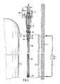
- Fig. 2 shows an embodiment of the device in which the structural element consists of a rod 1a guided inside an outer tube 2a, the tube and rod being firmly connected to one another at their lower ends by the screw connection 3a.
- the points 4a of the tube and 5a of the rod 1a are movable.
- the materials of the tube and rod are selected so that the tube has a higher coefficient of thermal expansion than the rod. This means that when the two bodies are heated, the gripper 13 connected to the upper end of the rod 1a is drawn deeper into the sleeve connected to the tube. From a certain depth, the gripper 13 grips the nut 15 of the valve tappet 12 and thus opens the safety valve 11.
- the device is arranged in the gap between the container 1 to be protected and the surface coolers 13 located on the inner surface of the wall 2. This ensures sufficient heat coupling to the container. This is due to the fact that the temperature is approximately in the gap if the surface cooler fails the container wall adjusts. The temperature rise in the container wall also takes place so slowly that the thermal expansion bodies can follow this temperature development without a large temperature difference.
Landscapes
- Physics & Mathematics (AREA)
- Engineering & Computer Science (AREA)
- Plasma & Fusion (AREA)
- General Engineering & Computer Science (AREA)
- High Energy & Nuclear Physics (AREA)
- Filling Or Discharging Of Gas Storage Vessels (AREA)
- Pressure Vessels And Lids Thereof (AREA)
- Structure Of Emergency Protection For Nuclear Reactors (AREA)
- Temperature-Responsive Valves (AREA)
- Heat-Pump Type And Storage Water Heaters (AREA)
Applications Claiming Priority (2)
| Application Number | Priority Date | Filing Date | Title |
|---|---|---|---|
| DE19863617524 DE3617524A1 (de) | 1986-05-24 | 1986-05-24 | Vorrichtung zur automatischen druckentlastung von temperaturgefaehrdeten behaeltern |
| DE3617524 | 1986-05-24 |
Publications (2)
| Publication Number | Publication Date |
|---|---|
| EP0247518A2 true EP0247518A2 (fr) | 1987-12-02 |
| EP0247518A3 EP0247518A3 (fr) | 1988-07-20 |
Family
ID=6301574
Family Applications (1)
| Application Number | Title | Priority Date | Filing Date |
|---|---|---|---|
| EP87107393A Withdrawn EP0247518A3 (fr) | 1986-05-24 | 1987-05-21 | Dispositif de dépressurisation des enceintes de pression en fonction de la température |
Country Status (4)
| Country | Link |
|---|---|
| US (1) | US4836443A (fr) |
| EP (1) | EP0247518A3 (fr) |
| JP (1) | JPS6312990A (fr) |
| DE (1) | DE3617524A1 (fr) |
Cited By (2)
| Publication number | Priority date | Publication date | Assignee | Title |
|---|---|---|---|---|
| DE4206658A1 (de) * | 1992-03-03 | 1993-09-09 | Siemens Ag | Sicherheitseinrichtung gegen ueberdruckversagen eines kernreaktor-druckbehaelters |
| DE4206660A1 (de) * | 1992-03-03 | 1993-09-09 | Siemens Ag | Sicherheitseinrichtung gegen ueberdruckversagen eines kernreaktor-druckbehaelters |
Families Citing this family (12)
| Publication number | Priority date | Publication date | Assignee | Title |
|---|---|---|---|---|
| DE4206661A1 (de) * | 1992-03-03 | 1993-09-09 | Siemens Ag | Sicherheitseinrichtung gegen ueberdruckversagen eines kernreaktor-druckbehaelters |
| US5519743A (en) * | 1994-09-02 | 1996-05-21 | Westinghouse Electric Corporation | Primary coolant system of a nuclear power plant for providing coolant to a primary loop |
| US5613634A (en) * | 1994-10-24 | 1997-03-25 | Westinghouse Electric Corporation | Passively ambient temperature actuated fluid valve |
| US5564584A (en) * | 1995-01-13 | 1996-10-15 | Western Industries, Inc. | Vent cap for discharging nearly empty propane cylinders |
| US5684846A (en) * | 1995-09-21 | 1997-11-04 | Westinghouse Electric Corporation | Nuclear reactor plant having containment isolation |
| DE10041779C1 (de) | 2000-08-25 | 2002-02-07 | Rossendorf Forschzent | Steuereinrichtung für einen Kühlkreislauf |
| CN100434190C (zh) * | 2003-10-09 | 2008-11-19 | 埃克希姆公司 | 用于热喷涂的装置 |
| US8800588B2 (en) | 2011-12-13 | 2014-08-12 | GM Global Technology Operations LLC | Glass bulb thermally-activated pressure relief device, safety inspection method, and equipment |
| US9721685B2 (en) * | 2012-04-17 | 2017-08-01 | Bwxt Mpower, Inc. | Valve assembly with isolation valve vessel |
| CN103335164B (zh) * | 2013-07-23 | 2016-08-10 | 北京汉威机电股份有限公司 | 一种防火阀及其外温感装置 |
| JP6945920B2 (ja) * | 2015-10-30 | 2021-10-06 | 一般財団法人電力中央研究所 | コンクリートキャスクの冷却空気量調節装置及びコンクリートキャスク |
| CN116168854A (zh) * | 2023-02-13 | 2023-05-26 | 深圳中广核工程设计有限公司 | 反应堆压力容器保护方法及系统 |
Family Cites Families (20)
| Publication number | Priority date | Publication date | Assignee | Title |
|---|---|---|---|---|
| BE528227A (fr) * | ||||
| US808707A (en) * | 1905-08-11 | 1906-01-02 | William B Wadsworth | Temperature-regulating means. |
| US867560A (en) * | 1906-03-06 | 1907-10-01 | Charles T Sears | Regulating-valve for liquid-fuel burners. |
| US1231044A (en) * | 1911-09-14 | 1917-06-26 | Robert S Mayer | Thermostatic valve. |
| US1726068A (en) * | 1927-08-12 | 1929-08-27 | Baker Ice Machine Co Inc | Thermostatic flow regulator |
| US1735415A (en) * | 1928-04-18 | 1929-11-12 | Andrew G Spinney | Safety device for hot-water boilers |
| US1927036A (en) * | 1930-01-10 | 1933-09-19 | Honeywell Regulator Co | Safety relief valve for hot water heating systems |
| DE832979C (de) * | 1950-06-03 | 1952-03-03 | Basf Ag | Sicherheitsventil fuer UEberdruecke und UEbertemperaturen |
| US2806455A (en) * | 1953-02-12 | 1957-09-17 | Bell & Gossett Co | Apparatus for preventing overheating of a hot water boiler |
| US2760343A (en) * | 1953-06-22 | 1956-08-28 | Phillips Petroleum Co | Emergency tank depressuring valve systems and processes |
| US2843325A (en) * | 1954-06-01 | 1958-07-15 | Garrett Corp | Thermostatic controls |
| US2849188A (en) * | 1955-07-11 | 1958-08-26 | Breese Burners Inc | Floatless heat responsive valve for liquid burners |
| US3154248A (en) * | 1963-01-16 | 1964-10-27 | Manstfield Sanitary Inc | Temperature control relief valve |
| US3306109A (en) * | 1963-07-11 | 1967-02-28 | Robertshaw Controls Co | Insulator insert for thermal sensing device |
| DE1185362B (de) * | 1963-09-19 | 1965-01-14 | Beteiligungs & Patentverw Gmbh | Behaelter fuer hohen Innendruck, insbesondere Druckbehaelter eines Kernreaktors |
| US3447746A (en) * | 1966-10-17 | 1969-06-03 | Emerson Electric Co | Burner control device for a water heater |
| JPS4988121A (fr) * | 1972-12-08 | 1974-08-23 | ||
| US4452184A (en) * | 1981-11-05 | 1984-06-05 | Honeywell-Braukmann Gmbh | Boiler draft control device |
| DE3421654A1 (de) * | 1984-06-09 | 1985-12-12 | Kernforschungszentrum Karlsruhe Gmbh, 7500 Karlsruhe | Entlastungsvorrichtung fuer den sicherheitsbehaelter eines druckwasserkernreaktors |
| DE3526377A1 (de) * | 1985-07-24 | 1987-02-05 | Kernforschungsanlage Juelich | Kernreaktor, insbesondere hochtemperaturreaktor |
-
1986
- 1986-05-24 DE DE19863617524 patent/DE3617524A1/de active Granted
-
1987
- 1987-05-21 EP EP87107393A patent/EP0247518A3/fr not_active Withdrawn
- 1987-05-22 JP JP62124086A patent/JPS6312990A/ja active Pending
-
1988
- 1988-05-18 US US07/198,636 patent/US4836443A/en not_active Expired - Fee Related
Cited By (6)
| Publication number | Priority date | Publication date | Assignee | Title |
|---|---|---|---|---|
| DE4206658A1 (de) * | 1992-03-03 | 1993-09-09 | Siemens Ag | Sicherheitseinrichtung gegen ueberdruckversagen eines kernreaktor-druckbehaelters |
| DE4206660A1 (de) * | 1992-03-03 | 1993-09-09 | Siemens Ag | Sicherheitseinrichtung gegen ueberdruckversagen eines kernreaktor-druckbehaelters |
| WO1993018523A1 (fr) * | 1992-03-03 | 1993-09-16 | Siemens Aktiengesellschaft | Dispositif de prevention de defaillance due a la surpression de la cuve sous pression d'un reacteur nucleaire |
| FR2688927A1 (fr) * | 1992-03-03 | 1993-09-24 | Siemens Ag | Dispositif de securite contre une defaillance d'une surpression d'un caisson sous pression d'un reacteur nucleaire. |
| US5517538A (en) * | 1992-03-03 | 1996-05-14 | Siemens Aktiengesellschaft | Safety device protecting a nuclear reactor pressure vessel against overpressure failure |
| US5526385A (en) * | 1992-03-03 | 1996-06-11 | Siemens Aktiengesellschaft | Safety device protecting against overpressure failure of a nuclear reactor pressure vessel |
Also Published As
| Publication number | Publication date |
|---|---|
| US4836443A (en) | 1989-06-06 |
| JPS6312990A (ja) | 1988-01-20 |
| EP0247518A3 (fr) | 1988-07-20 |
| DE3617524A1 (de) | 1987-11-26 |
| DE3617524C2 (fr) | 1988-02-25 |
Similar Documents
| Publication | Publication Date | Title |
|---|---|---|
| EP0247518A2 (fr) | Dispositif de dépressurisation des enceintes de pression en fonction de la température | |
| DE2524800A1 (de) | Freigabevorrichtung fuer ein steuerelement | |
| DE2825439A1 (de) | Sicherheitsvorrichtung fuer kernreaktoren | |
| DE2638181C2 (de) | Wärmetauscher-Auflager | |
| DE1145874B (de) | Sperrvorrichtung fuer einen in die OEffnung eines Behaelters dichtend einsetzbaren Verschlusskoerper | |
| DE2818737A1 (de) | Gegengewicht- und stossdaempfungssystem | |
| DE1958152B2 (de) | Klemmsystem für einen Reaktorkern | |
| DE3526377C2 (fr) | ||
| DE2801005C2 (de) | Vorrichtung zur Reaktivitätssteuerung | |
| DE2510062C3 (de) | Teleskopeinrichtung für Kernenergieanlagen | |
| DE2930633A1 (de) | Vorrichtung zum betaetigen eines steuerstabs eines reaktors | |
| DE69409470T2 (de) | Sicherheitsvorrichtung zur Öffnung oder Schliessung eines Schiebers | |
| EP0169471A2 (fr) | Outil pour extraire un tube d'une paroi tubulaire | |
| DE3005574C2 (fr) | ||
| CH626708A5 (en) | Device for controlling the opening and closing of a ventilation opening by means of at least one flap | |
| DE2409867B2 (de) | Absperr- und sicherheitseinrichtung fuer die frischdampfleitungen eines dampferzeugers | |
| DE1105531B (de) | Durch Graphit moderierter Kernreaktor mit positivem Temperaturkoeffizienten des Moderatoreinflusses auf die Reaktivitaet | |
| EP1410402B1 (fr) | Dispositif de commande pour un circuit de refroidissement | |
| DE2726759C3 (de) | Einrichtung zum Greifen und Anheben vertikal angeordneter, länglicher Bauelemente aus der aktiven Zone eines Kernreaktors | |
| DE4212284A1 (de) | Vorrichtung zum Abschalten von Kernreaktoren | |
| EP0752079B1 (fr) | Appareil de robinetterie sous pression, utile notamment comme soupape de detente et de securite | |
| EP0870140B1 (fr) | Soupape de securite, notamment soupape de detente et soupape de surpression | |
| DE1514158C (de) | Sicherheitskupplung für einen Kernreaktor-Steuerstab | |
| EP0870141B1 (fr) | Soupape d'arret | |
| DE2618647C2 (de) | Einrichtung zum Verringern der Fallgeschwindigkeit eines Brennelement-Transportbehälters |
Legal Events
| Date | Code | Title | Description |
|---|---|---|---|
| PUAI | Public reference made under article 153(3) epc to a published international application that has entered the european phase |
Free format text: ORIGINAL CODE: 0009012 |
|
| AK | Designated contracting states |
Kind code of ref document: A2 Designated state(s): CH FR GB LI SE |
|
| PUAL | Search report despatched |
Free format text: ORIGINAL CODE: 0009013 |
|
| AK | Designated contracting states |
Kind code of ref document: A3 Designated state(s): CH FR GB LI SE |
|
| 17P | Request for examination filed |
Effective date: 19881229 |
|
| RAP3 | Party data changed (applicant data changed or rights of an application transferred) |
Owner name: FORSCHUNGSZENTRUM JUELICH GMBH |
|
| 17Q | First examination report despatched |
Effective date: 19900910 |
|
| 18W | Application withdrawn |
Withdrawal date: 19910112 |
|
| STAA | Information on the status of an ep patent application or granted ep patent |
Free format text: STATUS: THE APPLICATION HAS BEEN WITHDRAWN |
|
| R18W | Application withdrawn (corrected) |
Effective date: 19910112 |
|
| RIN1 | Information on inventor provided before grant (corrected) |
Inventor name: ESCHERICH, KARL-HEINZ Inventor name: WOLTERS, JOHANNES-PETER, DR. |