EP0247518A2 - Device for the temperature-dependent pressure release of pressure vessels - Google Patents
Device for the temperature-dependent pressure release of pressure vessels Download PDFInfo
- Publication number
- EP0247518A2 EP0247518A2 EP87107393A EP87107393A EP0247518A2 EP 0247518 A2 EP0247518 A2 EP 0247518A2 EP 87107393 A EP87107393 A EP 87107393A EP 87107393 A EP87107393 A EP 87107393A EP 0247518 A2 EP0247518 A2 EP 0247518A2
- Authority
- EP
- European Patent Office
- Prior art keywords
- temperature
- pressure vessel
- pressure
- container
- shut
- Prior art date
- Legal status (The legal status is an assumption and is not a legal conclusion. Google has not performed a legal analysis and makes no representation as to the accuracy of the status listed.)
- Withdrawn
Links
Images

Classifications
-
- G—PHYSICS
- G21—NUCLEAR PHYSICS; NUCLEAR ENGINEERING
- G21C—NUCLEAR REACTORS
- G21C9/00—Emergency protection arrangements structurally associated with the reactor, e.g. safety valves provided with pressure equalisation devices
-
- Y—GENERAL TAGGING OF NEW TECHNOLOGICAL DEVELOPMENTS; GENERAL TAGGING OF CROSS-SECTIONAL TECHNOLOGIES SPANNING OVER SEVERAL SECTIONS OF THE IPC; TECHNICAL SUBJECTS COVERED BY FORMER USPC CROSS-REFERENCE ART COLLECTIONS [XRACs] AND DIGESTS
- Y02—TECHNOLOGIES OR APPLICATIONS FOR MITIGATION OR ADAPTATION AGAINST CLIMATE CHANGE
- Y02E—REDUCTION OF GREENHOUSE GAS [GHG] EMISSIONS, RELATED TO ENERGY GENERATION, TRANSMISSION OR DISTRIBUTION
- Y02E30/00—Energy generation of nuclear origin
- Y02E30/30—Nuclear fission reactors
Definitions
- the invention relates to a device for temperature-dependent pressure relief of pressure vessels, in which a shut-off device provided in a discharge line of the pressure vessel is opened at a predetermined temperature.
- Such pressure vessels with possibly internal heat sources should be relieved of pressure when the vessel temperature has reached the predetermined value. This can happen, for example, if the existing automatic cooling fails.
- Such containers can be found, for example, in small high-temperature reactors. These reactors have steel pressure vessels, which must not be heated above 400 ° C at operating pressure. Small high-temperature reactors are designed in such a way that the after-heating power resulting from the decay of the radioactive fission products is released to the surface cooler surrounding the container via the surface of the container if the forced cooling fails, without permissible temperatures inside the container or in the container wall being exceeded. The tank temperature only rises above 400 ° C if the redundant surface cooler fails. A While this is very unlikely, it is the only mechanism that could compromise the integrity of the reactor pressure vessel.
- the pressure vessel is only protected against excessive pressure by one or more safety valves staggered in response pressure.
- the state of the art includes safety valves that can be opened against the closing force via a drive.
- a disadvantage of these valves is that control errors can lead to the primary circuit being opened unintentionally.
- the object of the invention is to provide a device for pressure relief of containers of the type mentioned, by means of which the container is opened automatically and with high reliability via the shut-off elements when the permissible temperature is exceeded, without the need for additional auxiliary energy.
- This object is achieved according to the invention in that an elongated structural element acted upon by the temperature of the pressure vessel is provided, one end of which is fixed in place and the other end which is deflected depending on the temperature expansion is mechanically connected to the shut-off element.
- the thermal expansion of the structural element, which is in the temperature range of the container, is used to actuate the shut-off element.
- the pressure vessel itself is the structural element.
- the container can be, for example, an upright, long steel cylinder which is fixed in place at its lower end. As a result, the upper part of the container moves upward when the container is heated.
- a wall is arranged next to the container, for example, which is also fixed in place on the support (bottom).
- the container closure and a point corresponding to the height of the wall are movable relative to one another. They are connected to each other with a lever mechanism that absorbs the relative movement of the points. If the relative movement exceeds a certain dimension, a spring-loaded safety valve is opened, for example, via the lever mechanism.
- the relative movement of the movable points can of course also be used to open other shut-off devices. Obvious examples are: the puncture of a space membrane or the opening of a non-return valve against the pending container pressure.
- the structural element is a rod arranged adjacent to the pressure vessel.
- the rod can be freely movable in a tube, both of which are connected to one another at one end.
- Containers and rods are made of materials with different thermal expansion and are arranged so that both are heated to the same temperature via the container wall. If the temperature rises, the free ends of the body (the upper end of the container and the free end of the rod) move relative to each other. This displacement is transferred to the tappet of a safety valve if it exceeds a certain level. The safety valve is opened in this way.
- the device according to the invention is characterized by its completely autonomous function. Neither control nor auxiliary power is required, since the container temperature to be monitored is used directly to carry out the necessary protective action via the thermal expansion of the container itself or via expansion bodies (the structural element) thermally coupled to the container. This guarantees high reliability when required. Since the device is used in connection with an existing safety valve and the mechanism cannot be activated except by the temperature of the container being exceeded, the probability of the container being accidentally opened is practically not increased. Monitoring the operational readiness during operation, as with a pneumatic or hydraulic drive, is not necessary. The technical effort as a whole and the associated costs are extremely low, although a considerable degree of additional security is achieved.
- the vertical cylindrical steel pressure vessel 1 itself is the structural element next to which the wall 2 is arranged.
- the pressure vessel and wall are fixed in place on the floor 3.
- the intermediate mechanism consisting of parts 6 - 9 is attached to the movable points 4 and 5 of the container or wall.
- Lever 6 is articulated with a vertical play at the movable point 4 of the container 1, and the vertical play (due to the eyelet 10) is designed so that the articulation point of the lever 6 is only moved above a certain thermal expansion of the upwardly expanding container .
- the other end of the lever is fixed in the vertical direction by the concrete wall 2 and the cantilever 7.
- the articulated lever 8 prevents the container from being fixed horizontally and thereby ensures that the mechanism is not loaded in the event of an earthquake.
- the spring-loaded safety valve 11 is also fixed by the wall 2. The result of this is that the valve tappet 12 of the safety valve 11 is raised above the joint part 9 as soon as the thermal expansion of the container moves the end of the lever 6 articulated on the container upwards.
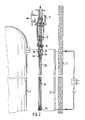
- Fig. 2 shows an embodiment of the device in which the structural element consists of a rod 1a guided inside an outer tube 2a, the tube and rod being firmly connected to one another at their lower ends by the screw connection 3a.
- the points 4a of the tube and 5a of the rod 1a are movable.
- the materials of the tube and rod are selected so that the tube has a higher coefficient of thermal expansion than the rod. This means that when the two bodies are heated, the gripper 13 connected to the upper end of the rod 1a is drawn deeper into the sleeve connected to the tube. From a certain depth, the gripper 13 grips the nut 15 of the valve tappet 12 and thus opens the safety valve 11.
- the device is arranged in the gap between the container 1 to be protected and the surface coolers 13 located on the inner surface of the wall 2. This ensures sufficient heat coupling to the container. This is due to the fact that the temperature is approximately in the gap if the surface cooler fails the container wall adjusts. The temperature rise in the container wall also takes place so slowly that the thermal expansion bodies can follow this temperature development without a large temperature difference.
Landscapes
- Physics & Mathematics (AREA)
- Engineering & Computer Science (AREA)
- Plasma & Fusion (AREA)
- General Engineering & Computer Science (AREA)
- High Energy & Nuclear Physics (AREA)
- Filling Or Discharging Of Gas Storage Vessels (AREA)
- Pressure Vessels And Lids Thereof (AREA)
- Structure Of Emergency Protection For Nuclear Reactors (AREA)
- Temperature-Responsive Valves (AREA)
- Heat-Pump Type And Storage Water Heaters (AREA)
Abstract
Die Erfindung bezieht sich auf eine Vorrichtung zur temperaturabhängigen Druckentlastung von Druckbehältern (1), bei der ein in einer Abgasleitung des Druckbehälters vorgesehenes Absperrorgan (11) bei einer vorgegebenen Temperatur geöffnet wird. Ziel ist es, eine derartige Vorrichtung zu schaffen, die automatisch und mit hoher Zuverlässigkeit arbeitet und die ohne zusätzliche Hilfsenergie auskommt. Die Lösung dieser Aufgabe besteht in einem von der Temperatur des Druckbehälters (1) beaufschlagten länglichen Konstruktionselement, dessen eines Ende ortsfest fixiert (30) und dessen anderes in Abhängigkeit von der Temperaturausdehnung ausgelenktes Ende mechanisch mit dem Absperrorgan (11) verbunden ist. Bei einer besonderen Ausführungsform der Vorrichtung ist der Druckbehälter selbst das Konstruktionselement, bei einer anderen Ausführungsform eine benachbart zu dem Druckbehälter angeordnete Stange. 
Description
Die Erfindung bezieht sich auf eine Vorrichtung zur temperaturabhängigen Druckentlastung von Druckbehältern, bei der ein in einer Ablaßleitung des Druckbehälters vorgesehenes Absperrorgan bei einer vorgegebenen Temperatur geöffnet wird.The invention relates to a device for temperature-dependent pressure relief of pressure vessels, in which a shut-off device provided in a discharge line of the pressure vessel is opened at a predetermined temperature.
Derartige Druckbehälter mit ggf. inneren Wärmequellen sollen dann, wenn die Behältertemperatur den vorgegebenen Wert erreicht hat, druckentlastet werden. Dieser Fall kann beispielsweise eintreten, wenn die vorhandene automatische Kühlung ausfällt.Such pressure vessels with possibly internal heat sources should be relieved of pressure when the vessel temperature has reached the predetermined value. This can happen, for example, if the existing automatic cooling fails.
Solche Behälter findet man z.B. bei kleinen Hochtemperaturreaktoren. Diese Reaktoren haben Stahldruckbehälter, die bei Betriebsdruck nicht über 400 °C aufgeheizt werden dürfen. Kleine Hochtemperaturreaktoren sind so konstruiert, daß die durch den Zerfall der radioaktiven Spaltprodukte entstehende Nachwärmeleistung bei Ausfall der Zwangskühlung über die Behälteroberfläche an den Behälter umgebende Flächenkühler abgegeben wird, ohne daß zulässige Temperaturen im Inneren des Behälters oder in der Behälterwand überschritten werden. Nur bei Ausfall der redundanten Flächenkühler steigt die Behältertemperatur über 400 °C an. Ein solcher Fall ist zwar sehr unwahrscheinlich, stellt aber den einzigen Mechanismus dar, der die Integrität des Reaktordruckbehälters gefährden könnte.Such containers can be found, for example, in small high-temperature reactors. These reactors have steel pressure vessels, which must not be heated above 400 ° C at operating pressure. Small high-temperature reactors are designed in such a way that the after-heating power resulting from the decay of the radioactive fission products is released to the surface cooler surrounding the container via the surface of the container if the forced cooling fails, without permissible temperatures inside the container or in the container wall being exceeded. The tank temperature only rises above 400 ° C if the redundant surface cooler fails. A While this is very unlikely, it is the only mechanism that could compromise the integrity of the reactor pressure vessel.
Üblicherweise wird der Druckbehälter von einem oder mehreren im Ansprechdruck gestaffelten Sicherheitsventilen nur vor zu hohem Druck geschützt. Zum Stand der Technik gehören Sicherheitsventile, die sich über einen Antrieb gegen die Schließkraft öffnen lassen. Nachteilig bei diesen Ventilen ist, daß Steuerungsfehler zu einem unbeabsichtigten Öffnen des Primärkreislaufs führen können. Außerdem ist man beim Öffnen auf Hilfsenergie angewiesen.Usually, the pressure vessel is only protected against excessive pressure by one or more safety valves staggered in response pressure. The state of the art includes safety valves that can be opened against the closing force via a drive. A disadvantage of these valves is that control errors can lead to the primary circuit being opened unintentionally. In addition, you have to rely on auxiliary energy when opening.
Aufgabe der Erfindung ist es, eine Vorrichtung zur Druckentlastung von Behältern der eingangs bezeichneten Art zu schaffen, mittels der der Behälter bei Überschreiten der zulässigen Temperatur automatisch und mit hoher Zuverlässigkeit über die Absperrorgane geöffnet wird, ohne daß zusätzliche Hilfsenergie benötigt wird.The object of the invention is to provide a device for pressure relief of containers of the type mentioned, by means of which the container is opened automatically and with high reliability via the shut-off elements when the permissible temperature is exceeded, without the need for additional auxiliary energy.
Diese Aufgabe wird gemäß der Erfindung dadurch gelöst, daß ein von der Temperatur des Druckbehälters beaufschlagtes längliches Konstruktionselement vorgesehen ist, dessen eines Ende ortsfest fixiert und dessen anderes in Abhängigkeit von der Temperaturausdehnung ausgelenktes Ende mechanisch mit dem Absperrorgan verbunden ist. Dabei wird die Wärmeausdehnung des Konstruktionselementes, das sich im Temperaturbereich des Behälters befindet, zur Betätigung des Absperrorgans genutzt.This object is achieved according to the invention in that an elongated structural element acted upon by the temperature of the pressure vessel is provided, one end of which is fixed in place and the other end which is deflected depending on the temperature expansion is mechanically connected to the shut-off element. The thermal expansion of the structural element, which is in the temperature range of the container, is used to actuate the shut-off element.
Eine vorteilhafte Ausführungsart der Vorrichtung gemäß der Erfindung besteht darin, daß der Druckbehälter selbst das Konstruktionselement ist. Der Behälter kann beispielsweise ein aufrecht stehender langer Stahlzylinder sein, der an seinem unteren Ende ortsfest fixiert ist. Demzufolge verschiebt sich der obere Teil des Behälters bei Aufheizung des Behälters nach oben. Neben dem Behälter ist beispielsweise eine Wand angeordnet, die ebenfalls auf der Auflage (Boden) ortsfest fixiert ist. Der Behälterabschluß und ein Punkt entsprechender Höhe der Wand sind relativ zueinander beweglich. Sie sind mit einer Hebelmechanik miteinander verbunden, die die Relativbewegung der Punkte aufnimmt. Übersteigt die Relativbewegung ein bestimmtes Maß, so wird über den Hebelmechanismus beispielsweise ein federbelastetes Sicherheitsventil geöffnet.An advantageous embodiment of the device according to the invention is that the pressure vessel itself is the structural element. The container can be, for example, an upright, long steel cylinder which is fixed in place at its lower end. As a result, the upper part of the container moves upward when the container is heated. A wall is arranged next to the container, for example, which is also fixed in place on the support (bottom). The container closure and a point corresponding to the height of the wall are movable relative to one another. They are connected to each other with a lever mechanism that absorbs the relative movement of the points. If the relative movement exceeds a certain dimension, a spring-loaded safety valve is opened, for example, via the lever mechanism.
Die Relativbewegung der beweglichen Punkte kann selbstverständlich auch zur Öffnung anderer Absperrorgane verwendet werden. Naheliegende Beispiele sind: das Durchstoßen einer Platzmembrane oder das Öffnen einer Rückschlagklappe gegen den anstehenden Behälterdruck.The relative movement of the movable points can of course also be used to open other shut-off devices. Obvious examples are: the puncture of a space membrane or the opening of a non-return valve against the pending container pressure.
Eine weitere Ausführungsart der Vorrichtung gemäß der Erfindung besteht darin, daß das Konstruktionselement eine benachbart zu dem Druckbehälter angeordnete Stange ist. Die Stange kann in einem Rohr frei beweglich geführt sein, wobei beide an einem Ende miteinander verbunden sind. Behälter und Stange bestehen aus Werkstoffen unterschiedlicher Wärmeausdehnung und sind so angeordnet, daß beide über die Behälterwand auf die gleiche Temperatur aufgeheizt werden. Steigt die Temperatur, so verschieben sich die freien Körperenden (der obere Abschluß des Behälters und das freie Ende des Stabes) relativ zueinander. Diese Verschiebung wird auf den Stößel eines Sicherheitsventils übertragen, wenn sie ein bestimmtes Maß übersteigt. Das Sicherheitsventil wird so geöffnet.Another embodiment of the device according to the invention is that the structural element is a rod arranged adjacent to the pressure vessel. The rod can be freely movable in a tube, both of which are connected to one another at one end. Containers and rods are made of materials with different thermal expansion and are arranged so that both are heated to the same temperature via the container wall. If the temperature rises, the free ends of the body (the upper end of the container and the free end of the rod) move relative to each other. This displacement is transferred to the tappet of a safety valve if it exceeds a certain level. The safety valve is opened in this way.
Die Vorrichtung gemäß der Erfindung zeichnet sich durch ihre völlig autonome Funktion aus. Es ist weder eine Steuerung noch eine Hilfsenergie erfoderlich, da die zu überwachende Behältertemperatur über die Wärmedehnung des Behälters selbst oder über wärmetechnisch an den Behälter angekoppelte Expansionskörper (das Konstruktionselement) unmittelbar zur Durchführung der notwendigen Schutzaktion verwendet wird. Dies garantiert eine hohe Zuverlässigkeit im Anforderungsfall. Da die Vorrichtung in Verbindung mit einem ohnehin vorhandenen Sicherheitsventil verwendet wird und der Mechanismus außer durch Temperaturüberschreitung des Behälters nicht wirksam werden kann, wird die Wahrscheinlichkeit für ein zufälliges Öffnen des Behälters praktisch nicht erhöht. Eine Überwachung der Funktionsbereitschaft während des Betriebes wie bei einem pneumatischen oder hydraulichen Antrieb ist nicht erforderlich. Der technische Aufwand als ganzes und die damit verbundenen Kosten sind außerordentlich gering, obwohl ein beträchtliches Maß an zusätzlicher Sicherheit erreicht wird.The device according to the invention is characterized by its completely autonomous function. Neither control nor auxiliary power is required, since the container temperature to be monitored is used directly to carry out the necessary protective action via the thermal expansion of the container itself or via expansion bodies (the structural element) thermally coupled to the container. This guarantees high reliability when required. Since the device is used in connection with an existing safety valve and the mechanism cannot be activated except by the temperature of the container being exceeded, the probability of the container being accidentally opened is practically not increased. Monitoring the operational readiness during operation, as with a pneumatic or hydraulic drive, is not necessary. The technical effort as a whole and the associated costs are extremely low, although a considerable degree of additional security is achieved.
Ausführungsbeispiele der Vorrichtung gemäß der Erfindung sind in der Zeichnung schematisch dargestellt und werden im folgenden näher erläutert:Embodiments of the device according to the invention are shown schematically in the drawing and are explained in more detail below:
Es zeigen:
- Figur 1 eine aus Behälter und daneben angeordneter Wand mit Zwischenmechanik bestehende Vorrichtung gemäß der Erfindung;
Figur 2 eine aus Rohr und darin beweglich angeordnetem Stab bestehende Vorrichtung gemäß der Erfindung.
- 1 shows a device according to the invention consisting of a container and a wall arranged next to it with an intermediate mechanism;
- Figure 2 is a device consisting of a tube and a rod arranged movably therein according to the invention.
Bei der in Fig. 1 dargestellten Vorrichtung ist der senkrecht stehende zylindrische Stahldruckbehälter 1 selbst das Konstruktionselement, neben dem die Wand 2 angeordnet ist. Druckbehälter und Wand sind auf dem Boden 3 ortsfest fixiert. An den beweglichen Punkten 4 und 5 von Behälter bzw. Wand ist die aus den Teilen 6 - 9 bestehende Zwischenmechanik angebracht. Hebel 6 ist dabei mit einem vertikalen Spiel am beweglichen Punkt 4 des Behälters 1 angelenkt, und das vertikale Spiel (bedingt durch Öse 10) ist so ausgebildet, daß der Anlenkpunkt des Hebels 6 erst oberhalb einer bestimmten Wärmedehnung des sich nach oben ausdehnenden Behälters bewegt wird. Das andere Ende des Hebels ist durch die Betonwand 2 und den Kragbalken 7 in vertikaler Richtung fixiert. Der Gelenkhebel 8 verhindert eine horizontale Fixierung des Behälters und stellt dadurch sicher, daß der Mechanismus im Erdbebenfall nicht belastet wird.In the device shown in Fig. 1, the vertical cylindrical steel pressure vessel 1 itself is the structural element next to which the
Das federbelastete Sicherheitsventil 11 wird ebenfalls durch die Wand 2 fixiert. Das hat zur Folge, daß der Ventilstößel 12 des Sicherheitsventils 11 über das Gelenkteil 9 angehoben wird, sobald die Wärmedehnung des Behälters das am Behälter angelenkte Ende des Hebels 6 nach oben verschiebt.The spring-loaded
Fig. 2 zeigt eine Ausführungsart der Vorrichtung, bei der das Konstruktionselement aus einer in einem äußeren Rohr 2a innengeführten Stange 1a besteht, wobei Rohr und Stange an ihren unteren Enden durch die Verschraubung 3a fest miteinander verbunden sind. Die Punkte 4a des Rohres und 5a der Stange 1a sind beweglich. Die Werkstoffe von Rohr und Stange sind so gewählt, daß das Rohr einen höheren Wärmeausdehnungskoeffizienten aufweist als die Stange. Das bedeutet, daß bei Erwärmung der beiden Körper der mit dem oberen Ende der Stange 1a verbundene Greifer 13 tiefer in die mit dem Rohr verbundene Hülse hineingezogen wird. Ab einer bestimmten Tiefe erfaßt der Greifer 13 die Mutter 15 des Ventilstößels 12 und öffnet damit das Sicherheitsventil 11.Fig. 2 shows an embodiment of the device in which the structural element consists of a
Die Vorrichtung ist in dem Spalt zwischen dem zu schützenden Behälter 1 und den auf der Innenoberfläche der Wand 2 befindlichen Flächenkühlern 13 angeordnet. Eine ausreichende Wärmeankopplung an den Behälter ist dadurch gegeben. Dies liegt daran, daß sich im Spalt bei Ausfall der Flächenkühler annähernd die Temperatur der Behälterwand einstellt. Der Temperaturanstieg in der Behälterwand geht außerdem so langsam von statten, daß die Wärmedehnungskörper dieser Temperaturentwicklung ohne großen Temperaturunterschied folgen können.The device is arranged in the gap between the container 1 to be protected and the
Claims (3)
dadurch gekennzeichnet,
daß ein von der Temperatur des Druckbehälters beaufschlagtes längliches Konstrutionselement (1, 1a) vorgesehen ist, dessen eines Ende ortsfest fixiert und dessen anderes in Abhängigkeit von der Temperaturausdehnung ausgelenktes Ende mechanisch mit dem Absperrorgan (11) verbunden ist.1. Device for temperature-dependent pressure relief of pressure vessels, in which a shut-off device provided in a discharge line of the pressure vessel is opened at a predetermined temperature.
characterized,
that an elongated construction element (1, 1a) acted upon by the temperature of the pressure vessel is provided, one end of which is fixed in place and the other end which is deflected as a function of the temperature expansion is mechanically connected to the shut-off device (11).
dadurch gekennzeichnet,
daß das Konstruktionselement der Druckbehälter (1) ist.2. Device according to claim 1,
characterized,
that the structural element is the pressure vessel (1).
dadurch gekennzeichnet,
daß das Konstruktionselement eine benachbart zu dem Druckbehälter angeordnete Stange (1a) ist.3. Device according to claim 1,
characterized,
that the structural element is a rod (1a) arranged adjacent to the pressure vessel.
Applications Claiming Priority (2)
| Application Number | Priority Date | Filing Date | Title |
|---|---|---|---|
| DE3617524 | 1986-05-24 | ||
| DE19863617524 DE3617524A1 (en) | 1986-05-24 | 1986-05-24 | DEVICE FOR THE AUTOMATIC PRESSURE RELIEF OF TEMPERATURE HAZARDOUS TANKS |
Publications (2)
| Publication Number | Publication Date |
|---|---|
| EP0247518A2 true EP0247518A2 (en) | 1987-12-02 |
| EP0247518A3 EP0247518A3 (en) | 1988-07-20 |
Family
ID=6301574
Family Applications (1)
| Application Number | Title | Priority Date | Filing Date |
|---|---|---|---|
| EP87107393A Withdrawn EP0247518A3 (en) | 1986-05-24 | 1987-05-21 | Device for the temperature-dependent pressure release of pressure vessels |
Country Status (4)
| Country | Link |
|---|---|
| US (1) | US4836443A (en) |
| EP (1) | EP0247518A3 (en) |
| JP (1) | JPS6312990A (en) |
| DE (1) | DE3617524A1 (en) |
Cited By (2)
| Publication number | Priority date | Publication date | Assignee | Title |
|---|---|---|---|---|
| DE4206660A1 (en) * | 1992-03-03 | 1993-09-09 | Siemens Ag | SAFETY DEVICE AGAINST OVERPRESSURE FAILURE OF A CORE REACTOR PRESSURE TANK |
| DE4206658A1 (en) * | 1992-03-03 | 1993-09-09 | Siemens Ag | SAFETY DEVICE AGAINST OVERPRESSURE FAILURE OF A CORE REACTOR PRESSURE TANK |
Families Citing this family (12)
| Publication number | Priority date | Publication date | Assignee | Title |
|---|---|---|---|---|
| DE4206661A1 (en) * | 1992-03-03 | 1993-09-09 | Siemens Ag | SAFETY DEVICE AGAINST OVERPRESSURE FAILURE OF A CORE REACTOR PRESSURE TANK |
| US5519743A (en) * | 1994-09-02 | 1996-05-21 | Westinghouse Electric Corporation | Primary coolant system of a nuclear power plant for providing coolant to a primary loop |
| US5613634A (en) * | 1994-10-24 | 1997-03-25 | Westinghouse Electric Corporation | Passively ambient temperature actuated fluid valve |
| US5564584A (en) * | 1995-01-13 | 1996-10-15 | Western Industries, Inc. | Vent cap for discharging nearly empty propane cylinders |
| US5684846A (en) * | 1995-09-21 | 1997-11-04 | Westinghouse Electric Corporation | Nuclear reactor plant having containment isolation |
| DE10041779C1 (en) | 2000-08-25 | 2002-02-07 | Rossendorf Forschzent | Cooling circuit control device for emergency cooling of reactor pressure vessel uses actuator rod beneath base cap of reactor pressure vessel |
| CN100434190C (en) * | 2003-10-09 | 2008-11-19 | 埃克希姆公司 | Apparatus for thermal spraying |
| US8800588B2 (en) | 2011-12-13 | 2014-08-12 | GM Global Technology Operations LLC | Glass bulb thermally-activated pressure relief device, safety inspection method, and equipment |
| US9721685B2 (en) * | 2012-04-17 | 2017-08-01 | Bwxt Mpower, Inc. | Valve assembly with isolation valve vessel |
| CN103335164B (en) * | 2013-07-23 | 2016-08-10 | 北京汉威机电股份有限公司 | A kind of fire resisting damper and outer temp-sensing device thereof |
| JP6945920B2 (en) * | 2015-10-30 | 2021-10-06 | 一般財団法人電力中央研究所 | Cooling air amount control device for concrete cask and concrete cask |
| CN116168854A (en) * | 2023-02-13 | 2023-05-26 | 深圳中广核工程设计有限公司 | Reactor pressure vessel protection method and system |
Family Cites Families (20)
| Publication number | Priority date | Publication date | Assignee | Title |
|---|---|---|---|---|
| BE528227A (en) * | ||||
| US808707A (en) * | 1905-08-11 | 1906-01-02 | William B Wadsworth | Temperature-regulating means. |
| US867560A (en) * | 1906-03-06 | 1907-10-01 | Charles T Sears | Regulating-valve for liquid-fuel burners. |
| US1231044A (en) * | 1911-09-14 | 1917-06-26 | Robert S Mayer | Thermostatic valve. |
| US1726068A (en) * | 1927-08-12 | 1929-08-27 | Baker Ice Machine Co Inc | Thermostatic flow regulator |
| US1735415A (en) * | 1928-04-18 | 1929-11-12 | Andrew G Spinney | Safety device for hot-water boilers |
| US1927036A (en) * | 1930-01-10 | 1933-09-19 | Honeywell Regulator Co | Safety relief valve for hot water heating systems |
| DE832979C (en) * | 1950-06-03 | 1952-03-03 | Basf Ag | Safety valve for overpressures and excess temperatures |
| US2806455A (en) * | 1953-02-12 | 1957-09-17 | Bell & Gossett Co | Apparatus for preventing overheating of a hot water boiler |
| US2760343A (en) * | 1953-06-22 | 1956-08-28 | Phillips Petroleum Co | Emergency tank depressuring valve systems and processes |
| US2843325A (en) * | 1954-06-01 | 1958-07-15 | Garrett Corp | Thermostatic controls |
| US2849188A (en) * | 1955-07-11 | 1958-08-26 | Breese Burners Inc | Floatless heat responsive valve for liquid burners |
| US3154248A (en) * | 1963-01-16 | 1964-10-27 | Manstfield Sanitary Inc | Temperature control relief valve |
| US3306109A (en) * | 1963-07-11 | 1967-02-28 | Robertshaw Controls Co | Insulator insert for thermal sensing device |
| DE1185362B (en) * | 1963-09-19 | 1965-01-14 | Beteiligungs & Patentverw Gmbh | Container for high internal pressure, especially pressure vessel of a nuclear reactor |
| US3447746A (en) * | 1966-10-17 | 1969-06-03 | Emerson Electric Co | Burner control device for a water heater |
| JPS4988121A (en) * | 1972-12-08 | 1974-08-23 | ||
| US4452184A (en) * | 1981-11-05 | 1984-06-05 | Honeywell-Braukmann Gmbh | Boiler draft control device |
| DE3421654A1 (en) * | 1984-06-09 | 1985-12-12 | Kernforschungszentrum Karlsruhe Gmbh, 7500 Karlsruhe | RELIEF DEVICE FOR THE SECURITY CONTAINER OF A PRESSURE WATER CORE REACTOR |
| DE3526377A1 (en) * | 1985-07-24 | 1987-02-05 | Kernforschungsanlage Juelich | CORE REACTOR, PARTICULARLY HIGH TEMPERATURE REACTOR |
-
1986
- 1986-05-24 DE DE19863617524 patent/DE3617524A1/en active Granted
-
1987
- 1987-05-21 EP EP87107393A patent/EP0247518A3/en not_active Withdrawn
- 1987-05-22 JP JP62124086A patent/JPS6312990A/en active Pending
-
1988
- 1988-05-18 US US07/198,636 patent/US4836443A/en not_active Expired - Fee Related
Cited By (6)
| Publication number | Priority date | Publication date | Assignee | Title |
|---|---|---|---|---|
| DE4206660A1 (en) * | 1992-03-03 | 1993-09-09 | Siemens Ag | SAFETY DEVICE AGAINST OVERPRESSURE FAILURE OF A CORE REACTOR PRESSURE TANK |
| DE4206658A1 (en) * | 1992-03-03 | 1993-09-09 | Siemens Ag | SAFETY DEVICE AGAINST OVERPRESSURE FAILURE OF A CORE REACTOR PRESSURE TANK |
| WO1993018523A1 (en) * | 1992-03-03 | 1993-09-16 | Siemens Aktiengesellschaft | Safety device against the failure of a nuclear reactor pressure vessel due to overpressure |
| FR2688927A1 (en) * | 1992-03-03 | 1993-09-24 | Siemens Ag | DEVICE FOR SAFETY AGAINST A FAILURE OF A PRESSURE BOX PRESSURE OF A NUCLEAR REACTOR. |
| US5517538A (en) * | 1992-03-03 | 1996-05-14 | Siemens Aktiengesellschaft | Safety device protecting a nuclear reactor pressure vessel against overpressure failure |
| US5526385A (en) * | 1992-03-03 | 1996-06-11 | Siemens Aktiengesellschaft | Safety device protecting against overpressure failure of a nuclear reactor pressure vessel |
Also Published As
| Publication number | Publication date |
|---|---|
| DE3617524C2 (en) | 1988-02-25 |
| US4836443A (en) | 1989-06-06 |
| DE3617524A1 (en) | 1987-11-26 |
| EP0247518A3 (en) | 1988-07-20 |
| JPS6312990A (en) | 1988-01-20 |
Similar Documents
| Publication | Publication Date | Title |
|---|---|---|
| EP0247518A2 (en) | Device for the temperature-dependent pressure release of pressure vessels | |
| DE2524800A1 (en) | RELEASE DEVICE FOR A CONTROL ELEMENT | |
| DE2825439A1 (en) | SAFETY DEVICE FOR NUCLEAR REACTORS | |
| DE1958152C3 (en) | Clamping system for a reactor core | |
| DE2638181C2 (en) | Heat exchanger support | |
| DE2818737A1 (en) | COUNTERWEIGHT AND SHOCK ABSORBING SYSTEM | |
| DE3526377C2 (en) | ||
| DE2801005C2 (en) | Reactivity control device | |
| DE2510062C3 (en) | Telescopic device for nuclear power plants | |
| DE2930633A1 (en) | DEVICE FOR ACTUATING A CONTROL STAFF OF A REACTOR | |
| DE69409470T2 (en) | Safety device for opening or closing a slide | |
| EP0169471A2 (en) | Tool for extracting a tube from a tube sheet | |
| DE3005574C2 (en) | ||
| CH626708A5 (en) | Device for controlling the opening and closing of a ventilation opening by means of at least one flap | |
| DE2732903B2 (en) | Ejection inhibitor device for a control rod of a nuclear reactor attached to a control rod drive rod | |
| DE2409867B2 (en) | SHUT-OFF AND SAFETY DEVICE FOR THE FRESH STEAM PIPES OF A STEAM GENERATOR | |
| DE1105531B (en) | Nuclear reactor moderated by graphite with a positive temperature coefficient of the moderator influence on reactivity | |
| EP1410402B1 (en) | Control device for a cooling circuit | |
| DE2726759C3 (en) | Device for gripping and lifting vertically arranged, elongated components from the active zone of a nuclear reactor | |
| DE4212284A1 (en) | An automatic shut=down device for nuclear, esp. sodium cooled, reactors - based on an expansion device driven by coolant temperature rises | |
| EP0752079B1 (en) | Pressure fitting, useful in particular as pressure relief and safety valve | |
| EP0870140B1 (en) | Safety valve, in particular one designed as a pressure-relief and protection valve | |
| DE1514158C (en) | Safety coupling for a nuclear reactor control rod | |
| EP0870141B1 (en) | Check valve | |
| DE2618647C2 (en) | Device for reducing the speed of fall of a fuel assembly transport cask |
Legal Events
| Date | Code | Title | Description |
|---|---|---|---|
| PUAI | Public reference made under article 153(3) epc to a published international application that has entered the european phase |
Free format text: ORIGINAL CODE: 0009012 |
|
| AK | Designated contracting states |
Kind code of ref document: A2 Designated state(s): CH FR GB LI SE |
|
| PUAL | Search report despatched |
Free format text: ORIGINAL CODE: 0009013 |
|
| AK | Designated contracting states |
Kind code of ref document: A3 Designated state(s): CH FR GB LI SE |
|
| 17P | Request for examination filed |
Effective date: 19881229 |
|
| RAP3 | Party data changed (applicant data changed or rights of an application transferred) |
Owner name: FORSCHUNGSZENTRUM JUELICH GMBH |
|
| 17Q | First examination report despatched |
Effective date: 19900910 |
|
| 18W | Application withdrawn |
Withdrawal date: 19910112 |
|
| STAA | Information on the status of an ep patent application or granted ep patent |
Free format text: STATUS: THE APPLICATION HAS BEEN WITHDRAWN |
|
| R18W | Application withdrawn (corrected) |
Effective date: 19910112 |
|
| RIN1 | Information on inventor provided before grant (corrected) |
Inventor name: ESCHERICH, KARL-HEINZ Inventor name: WOLTERS, JOHANNES-PETER, DR. |