EP0247470A2 - Elektronenstrahlerzeugungssystem - Google Patents
Elektronenstrahlerzeugungssystem Download PDFInfo
- Publication number
- EP0247470A2 EP0247470A2 EP87107145A EP87107145A EP0247470A2 EP 0247470 A2 EP0247470 A2 EP 0247470A2 EP 87107145 A EP87107145 A EP 87107145A EP 87107145 A EP87107145 A EP 87107145A EP 0247470 A2 EP0247470 A2 EP 0247470A2
- Authority
- EP
- European Patent Office
- Prior art keywords
- electron beam
- embossing
- embossments
- grid electrode
- beam generating
- Prior art date
- Legal status (The legal status is an assumption and is not a legal conclusion. Google has not performed a legal analysis and makes no representation as to the accuracy of the status listed.)
- Granted
Links
Images
Classifications
-
- H—ELECTRICITY
- H01—ELECTRIC ELEMENTS
- H01J—ELECTRIC DISCHARGE TUBES OR DISCHARGE LAMPS
- H01J29/00—Details of cathode-ray tubes or of electron-beam tubes of the types covered by group H01J31/00
- H01J29/46—Arrangements of electrodes and associated parts for generating or controlling the ray or beam, e.g. electron-optical arrangement
- H01J29/48—Electron guns
- H01J29/50—Electron guns two or more guns in a single vacuum space, e.g. for plural-ray tube
- H01J29/503—Three or more guns, the axes of which lay in a common plane
Definitions
- the invention relates to an electron gun for color picture tubes according to the preamble of claim 1.
- EP-B-45 547 such an electron gun which has at least two grid electrodes.
- embossments are present on both sides in the area of the passage openings for the electron beams.
- the embossing of both sides takes place essentially simultaneously and their surfaces run parallel to one another and to the surfaces of the grid electrode.
- the pressure is so high that the embossing tools can break or have a very short service life.
- the invention has for its object an electron gun of the aforementioned Specify the type in which the grid electrodes are designed with a view to cost-effective production.
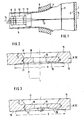
- Fig. 1 only a part of a color picture tube is shown for the better overview and this is then shown in section. The cut was made along the horizontal axis of the color picture tube.
- the color picture tube essentially consists of the screen trough 1 with the fluorescent screen 2 applied to the inner surface, the shadow mask 3 attached in front of it and the piston 4 which merges into the piston neck 5.
- the deflection unit 6 and, in it, the electron gun are mounted on the piston neck.
- the electron gun has three cathodes 7, which are surrounded by grid electrodes 8, the Wehnelt cylinders.
- the following screen grid, focusing electrodes and anodes are designated 9, 10 and 11, respectively. This is followed by a convergence pot 12.
- This structure of the electron gun can consist of individual electron guns or an integrated system. It is advantageous if individual electrodes of the system are designed so that they can be telescopically inserted into one another.
- the usual glass rods for holding the electron gun are not shown.
- the number of electrodes in each electron gun is not limited to four.
- the electron beams produced by the electron beam generation system are denoted by 13. Only the left and right ends of the tube axis 14, which represents the axis of symmetry of the color picture tube, are shown.
- FIG. 2 shows a section through a grid electrode 8 or 9, which is only partially shown.
- the base surface 18 of the embossing runs parallel to the side 15 and is at a distance t from it.
- embossing 20 On the side 19 of the grid electrode 8 or 9 facing the cathodes 7 there is an embossing 20 which is opposite the embossing 17. This embossing is circular and its diameter is labeled D.
- the base surface 21 of the embossing 20 is concave.
- the associated radius R is approximately 10 to 30 mm.
- the Distance between the two base surfaces 18 and 21 is denoted by d.
- the center of the concave embossment 20 lies on the axis of the passage opening 16.
- the material of the electrodes 8 and 9 can flow better to the outside in the area of the passage opening 16 during embossing. This creates less pressure during the stamping process and the stamping tool is not exposed to such a high load.
- this embossing can also have the shape of a truncated cone, which is shown in FIG. 3.
- the drawn opening angle ⁇ of the truncated cone is slightly less than 180 °.
- the embossing 20 it being important in each case that the distance d between the base surfaces 18 and 21 in the vicinity of the passage opening 16 is less than at the edge 18, where the distance is denoted by d ⁇ .
- the concave design of the embossing or its design in the form of a truncated cone can also be carried out in the embossing 17, the embossing 20 then having a rectangular shape.
Landscapes
- Electrodes For Cathode-Ray Tubes (AREA)
- Cathode-Ray Tubes And Fluorescent Screens For Display (AREA)
Abstract
Description
- Die Erfindung bezieht sich auf ein Elektronenstrahlerzeugungssystem für Farbbildröhren gemäß dem Oberbegriff des Anspruchs 1.
- Aus der EP-B-45 547 ist ein derartiges Elektronenstrahlerzeugungssystem bekannt, das mindestens zwei Gitterelektroden aufweist. In mindestens einer der Gitterelektroden sind im Bereich der Durchlaßöffnungen für die Elektronenstrahlen auf beiden Seiten Prägungen vorhanden. Beim Herstellen der Prägungen erfolgt das Prägen beider Seiten im wesentlichen gleichzeitig und ihre Flächen verlaufen parallel zueinander und zu den Oberflächen der Gitterelektrode. Beim Prägen derartiger Gitterelektroden entsteht ein so hoher Druck, daß die Prägewerkzeuge brechen können oder nur eine sehr kleine Standzeit haben.
- Der Erfindung liegt die Aufgabe zugrunde, ein Elektronenstrahlerzeugungssystem der eingangs genannten Art anzugeben, bei dem die Gitterelektroden im Hinblick auf eine kostengünstigere Fertigung ausgebildet sind.
- Die Lösung dieser Aufgabe erfolgt mit den im Anspruch 1 angegebenen Mitteln. Vorteilhafte Ausgestaltungen der Erfindung sind in den Unteransprüchen 2 bis 5 enthalten.
- Bei derartig ausgestalteten Gitterelektroden für Elektronenstrahlerzeugungssysteme wird die Belastung der Prägewerkzeuge in wirtschaftlich vertretbaren Grenzen gehalten und die Standzeit der Werkzeuge ist hinreichend groß.
- Die Erfindung wird nun anhand von in den Figuren gezeigten Ausführungsbeispielen näher erläutert. Es zeigen:
- Fig. 1 den Schnitt entlang der vertikalen Achse einer teilweise dargestellten Farbbildröhre;
- Fig. 2 einen Schnitt durch eine Gitterelektrode und
- Fig. 3 den Schnitt durch eine Gitterelektrode mit einer abgewandelten Ausführungsform der Prägungen.
- In Fig. 1 ist von einer Farbbildröhre der besseren übersicht weger nur ein Teil und dieser dann geschnitten dargestellt. Der Schnitt erfolgte entlang der horizontalen Achse der Farbbildröhre. Die Farbbildröhre besteht im wesentlichen aus der Schirmwanne 1 mit dem auf der Innenfläche aufgebrachten Leuchtschirm 2, der davor angebrachten Schattenmaske 3 und dem Kolben 4, der in den Kolbenhals 5 übergeht. Auf dem Kolbenhals ist die Ablenkeinheit 6 und in ihm das Elektronenstrahlerzeugungssystem angebracht.
- Das Elektronenstrahlerzeugungssystem weist drei Kathoden 7 auf, die von Gitterelektroden 8, den Wehneltzylindern, umgeben sind. Die nachfolgenden Schirmgitter-, Fokussierelektroden und Anoden sind mit 9, 10 bzw. 11 bezeichnet. Daran schließt sich ein Konvergenztopf 12 an. Dieser Aufbau des Elektronenstrahlerzeugungssystems kann aus einzelnen Elektronenstrahlerzeugern oder aus einem integrierten System bestehen. Es ist vorteilhaft, wenn einzelne Elektroden des Systems so ausgebildet sind, daß sie teleskopartig ineinandergefügt werden können. Die üblichen Glasstäbe zum Halten des Elektronenstrahlerzeugungssystems sind nicht dargestellt. Die Anzahl der Elektroden in jedem Elektronenstrahlerzeugungssystem ist nicht auf vier beschränkt. Die vom Elektronenstrahlerzeugungssystem hervorgebrachten Elektronenstrahlen sind mit 13 bezeichnet. Von der Röhrenachse 14, die die Symmetrieachse der Farbbildröhre darstellt, sind nur das linke und das rechte Ende dargestellt.
- In Fig. 2 ist ein Schnitt durch eine nur teilweise dargestellte Gitterelektrode 8 oder 9 dargestellt. Auf ihrer dem Leuchtschirm 2 zugewandten Seite 15 ist im Bereich der Durchlaßöffnung 16 für den Elektronenstrahl eine Prägung 17 vorhanden, die eine rechteckige Form aufweist. Die Grundfläche 18 der Prägung verläuft parallel zur Seite 15 und hat von ihr einen Abstand t.
- Auf der den Kathoden 7 zugewandten Seite 19 der Gitterelektrode 8 oder 9 ist eine Prägung 20 vorhanden, die der Prägung 17 gegenüberliegt. Diese Prägung ist kreisförmig und ihr Durchmesser ist mit D bezeichnet. Die Grundfläche 21 der Prägung 20 ist konkav ausgebildet. Der dazugehörige Radius R beträgt etwa 10 bis 30 mm. Der Abstand zwischen den beiden Grundflächen 18 und 21 is mit d bezeichnet. Das Zentrum der konkaven Prägung 20 liegt auf der Achse der Durchlaßöffnung 16.
- Durch diese Ausbildung der Prägung 20 kann das Material der Elektrode 8 bzw. 9 im Bereich der Durchlaßöffnung 16 beim Prägen besser nach außen abfließen. Hierdurch entsteht beim Prägevorgang weniger Druck und das Prägewerkzeug is keiner so hohen Belastung ausgesetzt.
- Anstatt der konkaven Ausbildung der Prägung 20, kann diese Prägung auch die Form eines Kegelstumpfes aufweisen, was in Fig. 3 dargestellt ist. Der eingezeichnte Öffnungswinkel α des Kegelstumpfes beträgt etwas weniger als 180°. Es sind noch weitere Ausbildungen für die Prägung 20 möglich, wobei jeweils wichtig ist, daß der Abstand d zwischen den Grundflächen 18 und 21 in der Nähe der Durchlaßöffnung 16 geringer ist als am Rand 18, wo der Abstand mit dʹ bezeichnet ist.
- Die konkave Ausbildung der Prägung oder deren Ausbildung in Form eines Kegelstumpfes kann auch bei der Prägung 17 vorgenommen werden, wobei dann die Prägung 20 eine rechteckige Form aufweist.
Claims (5)
Applications Claiming Priority (2)
| Application Number | Priority Date | Filing Date | Title |
|---|---|---|---|
| DE3617432 | 1986-05-23 | ||
| DE19863617432 DE3617432A1 (de) | 1986-05-23 | 1986-05-23 | Elektronenstrahlerzeugungssystem |
Publications (3)
| Publication Number | Publication Date |
|---|---|
| EP0247470A2 true EP0247470A2 (de) | 1987-12-02 |
| EP0247470A3 EP0247470A3 (en) | 1989-04-19 |
| EP0247470B1 EP0247470B1 (de) | 1992-04-22 |
Family
ID=6301511
Family Applications (1)
| Application Number | Title | Priority Date | Filing Date |
|---|---|---|---|
| EP87107145A Expired - Lifetime EP0247470B1 (de) | 1986-05-23 | 1987-05-18 | Elektronenstrahlerzeugungssystem |
Country Status (5)
| Country | Link |
|---|---|
| US (1) | US4891549A (de) |
| EP (1) | EP0247470B1 (de) |
| JP (2) | JPS62278741A (de) |
| CA (1) | CA1281360C (de) |
| DE (2) | DE3617432A1 (de) |
Cited By (3)
| Publication number | Priority date | Publication date | Assignee | Title |
|---|---|---|---|---|
| EP0293854A1 (de) * | 1987-06-05 | 1988-12-07 | Nokia (Deutschland) GmbH | Elektronenstrahlerzeugersystem |
| WO1990003042A1 (de) * | 1988-09-02 | 1990-03-22 | Nokia Unterhaltungselektronik (Deutschland) Gmbh | In-line-farbbildröhre |
| FR2647260A1 (fr) * | 1989-05-19 | 1990-11-23 | Thomson Tubes Electroniques | Electrode de commande pour canon a electrons de tube a rayons cathodiques |
Families Citing this family (11)
| Publication number | Priority date | Publication date | Assignee | Title |
|---|---|---|---|---|
| US5159240A (en) * | 1991-12-09 | 1992-10-27 | Chunghwa Picture Tubes, Ltd. | Low voltage limiting aperture electron gun |
| JPH05325828A (ja) | 1992-05-26 | 1993-12-10 | Hitachi Ltd | 陰極線管 |
| KR970008566B1 (ko) * | 1994-07-07 | 1997-05-27 | 엘지전자 주식회사 | 칼라 음극선관용 전자총의 제2그리드 |
| JP3429593B2 (ja) * | 1995-02-13 | 2003-07-22 | 株式会社日立製作所 | カラー陰極線管 |
| US5847500A (en) * | 1995-03-02 | 1998-12-08 | Hitachi, Ltd. | Electron gun for color cathode ray tube and method of manufacturing the electron gun electrode |
| KR100186540B1 (ko) | 1996-04-25 | 1999-03-20 | 구자홍 | 피디피의 전극 및 그 형성방법 |
| US6798526B2 (en) * | 2002-09-12 | 2004-09-28 | Seh America, Inc. | Methods and apparatus for predicting oxygen-induced stacking fault density in wafers |
| CN102488652B (zh) | 2006-03-16 | 2014-06-18 | 特瑞斯制药股份有限公司 | 含有药物-离子交换树脂复合物的经修饰释放的制剂 |
| CA2880456A1 (en) | 2012-08-15 | 2014-02-20 | Tris Pharma, Inc. | Methylphenidate extended release chewable tablet |
| US11590228B1 (en) | 2015-09-08 | 2023-02-28 | Tris Pharma, Inc | Extended release amphetamine compositions |
| US11590081B1 (en) | 2017-09-24 | 2023-02-28 | Tris Pharma, Inc | Extended release amphetamine tablets |
Family Cites Families (9)
| Publication number | Priority date | Publication date | Assignee | Title |
|---|---|---|---|---|
| BE759247A (fr) * | 1969-11-22 | 1971-05-21 | Philips Nv | Dispositif muni d'un tube electronique, et tube electronique destine a un tel dispositif |
| JPS6034783B2 (ja) * | 1976-07-29 | 1985-08-10 | 株式会社東芝 | 陰極線管 |
| JPS54117677A (en) * | 1978-03-06 | 1979-09-12 | Hitachi Ltd | Electron gun |
| JPS55154044A (en) * | 1979-05-18 | 1980-12-01 | Hitachi Ltd | Electrode structure of electron gun and its manufacture |
| US4319160A (en) * | 1979-11-15 | 1982-03-09 | North American Philips Consumer Electronics Corp. | One piece astigmatic grid for color picture tube electron gun and method of making same |
| EP0045547B1 (de) * | 1980-08-04 | 1984-09-26 | Philips ECG Inc. | Herstellungsverfahren eines Elektronenkanonenelementes für eine Kathodenstrahlröhre und mit einem nach diesem Verfahren hergestellten Elektronenkanonenelement versehene Kathodenstrahlröhre |
| US4500808A (en) * | 1982-04-02 | 1985-02-19 | Rca Corporation | Multibeam electron gun with composite electrode having plurality of separate metal plates |
| JPS59157936A (ja) * | 1983-02-24 | 1984-09-07 | Mitsubishi Electric Corp | インラインカラ−ブラウン管用電子銃 |
| US4661741A (en) * | 1985-06-28 | 1987-04-28 | Control Data Corporation | Miniature electron gun with focusing grid structure |
-
1986
- 1986-05-23 DE DE19863617432 patent/DE3617432A1/de active Granted
-
1987
- 1987-05-18 DE DE8787107145T patent/DE3778422D1/de not_active Expired - Lifetime
- 1987-05-18 EP EP87107145A patent/EP0247470B1/de not_active Expired - Lifetime
- 1987-05-20 US US07/052,714 patent/US4891549A/en not_active Expired - Lifetime
- 1987-05-22 CA CA000537699A patent/CA1281360C/en not_active Expired - Lifetime
- 1987-05-23 JP JP62125042A patent/JPS62278741A/ja active Pending
-
1993
- 1993-06-30 JP JP1993035727U patent/JP2574834Y2/ja not_active Expired - Fee Related
Cited By (3)
| Publication number | Priority date | Publication date | Assignee | Title |
|---|---|---|---|---|
| EP0293854A1 (de) * | 1987-06-05 | 1988-12-07 | Nokia (Deutschland) GmbH | Elektronenstrahlerzeugersystem |
| WO1990003042A1 (de) * | 1988-09-02 | 1990-03-22 | Nokia Unterhaltungselektronik (Deutschland) Gmbh | In-line-farbbildröhre |
| FR2647260A1 (fr) * | 1989-05-19 | 1990-11-23 | Thomson Tubes Electroniques | Electrode de commande pour canon a electrons de tube a rayons cathodiques |
Also Published As
| Publication number | Publication date |
|---|---|
| CA1281360C (en) | 1991-03-12 |
| JP2574834Y2 (ja) | 1998-06-18 |
| US4891549A (en) | 1990-01-02 |
| JPS62278741A (ja) | 1987-12-03 |
| DE3617432C2 (de) | 1991-07-18 |
| JPH0626143U (ja) | 1994-04-08 |
| DE3778422D1 (de) | 1992-05-27 |
| EP0247470B1 (de) | 1992-04-22 |
| EP0247470A3 (en) | 1989-04-19 |
| DE3617432A1 (de) | 1987-11-26 |
Similar Documents
| Publication | Publication Date | Title |
|---|---|---|
| DE2608463A1 (de) | Strahlsystem fuer eine kathodenstrahlroehre | |
| DE3143022C2 (de) | Inline-Elektronenstrahlsystem einer Farbbildröhre | |
| DE2850411C2 (de) | Elektronenstrahlerzeugungssystem in einer Kathodenstrahlröhre | |
| EP0247470B1 (de) | Elektronenstrahlerzeugungssystem | |
| DE3406784C2 (de) | ||
| DE2343777B2 (de) | Farbbildkathodenstrahlroehre | |
| DE2342110C2 (de) | Verfahren zur Herstellung eines Bildschirmes einer Farbbild-Kathodenstrahlröhre | |
| DE2454415C2 (de) | Farbbildwiedergaberöhre | |
| DE3107634A1 (de) | Farbbildroehre mit aberrationsarmer strahlfokussierungslinse | |
| DE2934993C2 (de) | Kathodenstrahlröhre mit mehreren Elektronenstrahlen | |
| DE2850369C2 (de) | Elektronenstrahlerzeugungssystem in einer Kathodenstrahlröhre | |
| DE2907300A1 (de) | Farbbildwiedergaberoehre | |
| DE2745180A1 (de) | Konstruktive ausbildung der schirmgitter-elektroden einer inline-farbbildroehre | |
| DE2511758A1 (de) | Farbbildroehre | |
| DE2846654A1 (de) | Farbbildroehre und verfahren zur herstellung einer derartigen farbbildroehre | |
| DE3218849C2 (de) | ||
| DE3307183C2 (de) | Inline-Elektronenstrahlerzeugungssystem mit einer verstärkten, tiefgezogenen Elektrode | |
| DE1812024A1 (de) | Vorrichtung mit einer Kathodenstrahlroehre,welche Vorrichtung mit einer Vierpollinse zur Ablenkverstaerkung versehen ist,und Kathodenstrahlroehre zur Anwendung in einer derartigen Vorrichtung | |
| DE3225634C2 (de) | Inline-Elektronenstrahlsystem | |
| DE3517401A1 (de) | Farbbildroehre, die einen schattenmaskenrahmen mit abgestumpften ecken hat | |
| DE3216039C2 (de) | Elektronenstrahl-Erzeugungssystem einer Kathodenstrahlröhre | |
| DE2619871A1 (de) | Kathodenstrahlroehre mit verbesserter schirmstruktur | |
| EP0090989B1 (de) | Elektronenoptik des Elektronenstrahlerzeugersystems einer Farbbildröhre | |
| DE3304209C2 (de) | Inline-Elektronenstrahlerzeugungssystem einer Farbbildröhre | |
| DE1080595B (de) | Kathodenstrahlroehre zur Wiedergabe von Farbfernsehbildern |
Legal Events
| Date | Code | Title | Description |
|---|---|---|---|
| PUAI | Public reference made under article 153(3) epc to a published international application that has entered the european phase |
Free format text: ORIGINAL CODE: 0009012 |
|
| AK | Designated contracting states |
Kind code of ref document: A2 Designated state(s): DE FR GB IT NL |
|
| RAP1 | Party data changed (applicant data changed or rights of an application transferred) |
Owner name: NOKIA GRAETZ GESELLSCHAFT MIT BESCHRAENKTER HAFTUN |
|
| PUAL | Search report despatched |
Free format text: ORIGINAL CODE: 0009013 |
|
| AK | Designated contracting states |
Kind code of ref document: A3 Designated state(s): DE FR GB IT NL |
|
| 17P | Request for examination filed |
Effective date: 19890526 |
|
| RAP1 | Party data changed (applicant data changed or rights of an application transferred) |
Owner name: NOKIA UNTERHALTUNGSELEKTRONIK (DEUTSCHLAND) GMBH |
|
| 17Q | First examination report despatched |
Effective date: 19901217 |
|
| GRAA | (expected) grant |
Free format text: ORIGINAL CODE: 0009210 |
|
| RAP1 | Party data changed (applicant data changed or rights of an application transferred) |
Owner name: NOKIA (DEUTSCHLAND) GMBH |
|
| AK | Designated contracting states |
Kind code of ref document: B1 Designated state(s): DE FR GB IT NL |
|
| ITF | It: translation for a ep patent filed | ||
| REF | Corresponds to: |
Ref document number: 3778422 Country of ref document: DE Date of ref document: 19920527 |
|
| ITTA | It: last paid annual fee | ||
| GBT | Gb: translation of ep patent filed (gb section 77(6)(a)/1977) | ||
| ET | Fr: translation filed | ||
| REG | Reference to a national code |
Ref country code: FR Ref legal event code: CD |
|
| PLBE | No opposition filed within time limit |
Free format text: ORIGINAL CODE: 0009261 |
|
| STAA | Information on the status of an ep patent application or granted ep patent |
Free format text: STATUS: NO OPPOSITION FILED WITHIN TIME LIMIT |
|
| 26N | No opposition filed | ||
| REG | Reference to a national code |
Ref country code: GB Ref legal event code: 732E |
|
| REG | Reference to a national code |
Ref country code: FR Ref legal event code: TP |
|
| REG | Reference to a national code |
Ref country code: GB Ref legal event code: IF02 |
|
| NLS | Nl: assignments of ep-patents |
Owner name: MATSUSHITA ELECTRIC INDUSTRIAL CO., LTD. |
|
| REG | Reference to a national code |
Ref country code: GB Ref legal event code: 732E |
|
| REG | Reference to a national code |
Ref country code: FR Ref legal event code: TP |
|
| PGFP | Annual fee paid to national office [announced via postgrant information from national office to epo] |
Ref country code: NL Payment date: 20060503 Year of fee payment: 20 |
|
| PGFP | Annual fee paid to national office [announced via postgrant information from national office to epo] |
Ref country code: FR Payment date: 20060515 Year of fee payment: 20 |
|
| PGFP | Annual fee paid to national office [announced via postgrant information from national office to epo] |
Ref country code: GB Payment date: 20060517 Year of fee payment: 20 |
|
| PGFP | Annual fee paid to national office [announced via postgrant information from national office to epo] |
Ref country code: IT Payment date: 20060531 Year of fee payment: 20 |
|
| PGFP | Annual fee paid to national office [announced via postgrant information from national office to epo] |
Ref country code: DE Payment date: 20060630 Year of fee payment: 20 |
|
| PG25 | Lapsed in a contracting state [announced via postgrant information from national office to epo] |
Ref country code: NL Free format text: LAPSE BECAUSE OF EXPIRATION OF PROTECTION Effective date: 20070518 |
|
| REG | Reference to a national code |
Ref country code: GB Ref legal event code: PE20 |
|
| NLV7 | Nl: ceased due to reaching the maximum lifetime of a patent |
Effective date: 20070518 |
|
| PG25 | Lapsed in a contracting state [announced via postgrant information from national office to epo] |
Ref country code: GB Free format text: LAPSE BECAUSE OF EXPIRATION OF PROTECTION Effective date: 20070517 |