EP0247004B1 - A multifunctional machine for fitting connectors onto tubes for hydraulic systems - Google Patents
A multifunctional machine for fitting connectors onto tubes for hydraulic systems Download PDFInfo
- Publication number
- EP0247004B1 EP0247004B1 EP87830010A EP87830010A EP0247004B1 EP 0247004 B1 EP0247004 B1 EP 0247004B1 EP 87830010 A EP87830010 A EP 87830010A EP 87830010 A EP87830010 A EP 87830010A EP 0247004 B1 EP0247004 B1 EP 0247004B1
- Authority
- EP
- European Patent Office
- Prior art keywords
- tube
- hydraulic systems
- tubes
- multifunctional machine
- connectors onto
- Prior art date
- Legal status (The legal status is an assumption and is not a legal conclusion. Google has not performed a legal analysis and makes no representation as to the accuracy of the status listed.)
- Expired - Lifetime
Links
Images
Classifications
-
- B—PERFORMING OPERATIONS; TRANSPORTING
- B23—MACHINE TOOLS; METAL-WORKING NOT OTHERWISE PROVIDED FOR
- B23P—METAL-WORKING NOT OTHERWISE PROVIDED FOR; COMBINED OPERATIONS; UNIVERSAL MACHINE TOOLS
- B23P23/00—Machines or arrangements of machines for performing specified combinations of different metal-working operations not covered by a single other subclass
-
- B—PERFORMING OPERATIONS; TRANSPORTING
- B23—MACHINE TOOLS; METAL-WORKING NOT OTHERWISE PROVIDED FOR
- B23B—TURNING; BORING
- B23B5/00—Turning-machines or devices specially adapted for particular work; Accessories specially adapted therefor
- B23B5/16—Turning-machines or devices specially adapted for particular work; Accessories specially adapted therefor for bevelling, chamfering, or deburring the ends of bars or tubes
-
- B—PERFORMING OPERATIONS; TRANSPORTING
- B23—MACHINE TOOLS; METAL-WORKING NOT OTHERWISE PROVIDED FOR
- B23D—PLANING; SLOTTING; SHEARING; BROACHING; SAWING; FILING; SCRAPING; LIKE OPERATIONS FOR WORKING METAL BY REMOVING MATERIAL, NOT OTHERWISE PROVIDED FOR
- B23D45/00—Sawing machines or sawing devices with circular saw blades or with friction saw discs
- B23D45/003—Sawing machines or sawing devices with circular saw blades or with friction saw discs for particular purposes
Definitions
- the present invention relates to a multifunctional machine capable of performing several different operations involved in fitting connectors onto rigid or flexible tubes to be used in hydraulic systems, such as hydraulic brake or clutch systems of motor vehicles.
- US-A-4,404,721 discloses a thread cutting machine for pipes comprising a machine base are which pipe holding chucks, a pipe rotation drive mechanism, a thread cutting mechanism and a threaded coupling holding chuck mechanism adapted to hold a threaded coupling such as socket, elbow or the like in position are provided.
- This machine is capable of fastening the threaded coupling to the pipe after the pipe threads have been formed as well as the inherent pipe cutting off and thread cutting functions.
- the object of the present invention is to eliminate the above-indicated disadvantages by providing a machine for fitting connectors onto tubes for hydraulic systems, which, in a small space, incorporates all the equipment necessary to allow all of these operations to be performed.
- a particular advantage of the present invention is that of providing a machine for the assembly of connectors onto tubes, especially rigid tubes for hydraulic systems, which is able drastically to reduce the time usually necessary for the correct fitting of connectors to the tubes themselves.
- Another advantage of the present invention is that it provides a machine for the assembly of connectors onto rigid tubes for hydraulic systems, which can be operate by only a single operator and which considerably facilitates the work thereof.
- the machine 1 is designed for cutting and bending rigid tubes and for fitting connectors thereto as will be more particularly described below: it is to be noted, however, that the invention may also be applied to the fitting of connectors to flexible tubes although certain differences in the process would then be required.
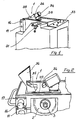
- the machine illustrated comprises a cropper, generally indicated 1, which is constituted by a circular saw blade 2 mounted on a shaft 3 borne at one end of a lever arm 4 which is pivoted so as to be turnable about the axis of the drive shaft of a motor 5 (see Figure 4) carrying a pair of toothed pulleys (not shown).
- a cropper generally indicated 1
- a circular saw blade 2 mounted on a shaft 3 borne at one end of a lever arm 4 which is pivoted so as to be turnable about the axis of the drive shaft of a motor 5 (see Figure 4) carrying a pair of toothed pulleys (not shown).
- One of these pulleys drives a toothed belt 6, tensioned by a belt tensioner pulley 7, which belt passes over a driven pulley 8 mounted in a fixed position on the said lever arm and fitted to the shaft carrying the circular saw 2.
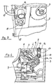
- the second of the said pulleys drives a toothed belt 9 which passes over a pulley 10a mounted on a spindle 10 carrying a de-burring tool 11 having a frusto-conical form and usable for cleaning off the burr on the inner edge of the end of a cut tube by means of longitudinal cutting discontinuities 12.
- the said spindle 10 also carries a second pulley 10b over which passes a toothed belt 13 which drives a corresponding pulley 14 mounted on a second spindle 15 carrying a further de-burring tool 16.
- This latter is constituted by a cylindrical element provided with a coaxial cavity of frusto-conical form able to clean the outer edge of the end of a cut tube.
- tube bending apparatus (not shown) by means of which bending of the cleaned tubes to any desired radius of curvature can be effected.
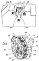
- the machine also includes an annular clinching structure with a horizontal axis, generally indicated with the reference numeral 18, which is constituted by a short cylinder 19 provided with a front flange 20, having a plurality of outwardly facing radial cavities 21 functioning as dies.
- This straight cylinder 19 is fixedly connected to a ring 22 carrying, on blocks 23, counterposed by pairs of helical springs 24, a corresponding number of punches 25 having a range of different diameters corresponding to the different sizes of the cavities in the front flange.
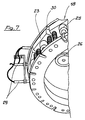
- the said annular structure is carried by three equiangularly spaced rollers 26, and is capable of being rotated about its axis by the action of a motor 27, preferably of hydraulic type, which drives a sprocket 28 which engages with a toothed ring (not shown) the teeth of which lie in a circle corresponding to the inner perimetral line of the annular structure itself.
- the rotation of this annular structure 18 is controlled by a proximity limit switch 29 the control members 30 of which are mounted on the said rear ring 22 and the front flange 20.
- control members 30 make it possible for the annular structure to be rotated to bring an appropriate punch and die into position in register with a frontal aperture 31 of a working station provided with an appropriate support recess 32 on which the end of a tube to be clinched to a collar by the apparatus is positioned in use of the machine.
- a control panel 33 ( Figure 1) having a selector by means of which the operator can pre-select the desired tool to be brought into register with the support 31 in dependence on the size of the tube to be fitted with connectors.
- the cutting tool constituted by the circular saw blade 2 is provided with a hydraulically controlled jaw 34 for clamping the tubes to be cut against a locator member 35, and a protective cowling 36 which covers a slot 38 through which the saw blade projects.
- the operator cleans it up by means of the rotating de-burring tools 11 and 16 and, possibly, bends it in dependence on the requirements of use. Subsequently, after having fitted the connection nut and the retaining ring or clinch ring onto the tube itself the operator subjects this latter to clinching by means of the selected punch and die of the appropriate size. Electronic control of the clinching pressures is provided so that all the clich rings, on tubes of the same diameter, are pressed with the same force.
- the connectors in question can be clinched also to the ends of suitably pre-arranged flexible tubes.
Applications Claiming Priority (2)
| Application Number | Priority Date | Filing Date | Title |
|---|---|---|---|
| IT20523/86A IT1188715B (it) | 1986-05-22 | 1986-05-22 | Macchina suscettibile di lavorazioni differenziate,per il montaggio di raccordi su tubi rigidi,utilizzati nella produzione di impianti oleodinamici in genere |
| IT2052386 | 1986-05-22 |
Publications (3)
| Publication Number | Publication Date |
|---|---|
| EP0247004A2 EP0247004A2 (en) | 1987-11-25 |
| EP0247004A3 EP0247004A3 (en) | 1988-08-03 |
| EP0247004B1 true EP0247004B1 (en) | 1991-04-24 |
Family
ID=11168215
Family Applications (1)
| Application Number | Title | Priority Date | Filing Date |
|---|---|---|---|
| EP87830010A Expired - Lifetime EP0247004B1 (en) | 1986-05-22 | 1987-01-15 | A multifunctional machine for fitting connectors onto tubes for hydraulic systems |
Country Status (3)
| Country | Link |
|---|---|
| EP (1) | EP0247004B1 (it) |
| DE (1) | DE3769513D1 (it) |
| IT (1) | IT1188715B (it) |
Family Cites Families (9)
| Publication number | Priority date | Publication date | Assignee | Title |
|---|---|---|---|---|
| US1835179A (en) * | 1928-10-17 | 1931-12-08 | Parker Arthur La Rue | Flaring tool for shaping pipe ends |
| US2675050A (en) * | 1951-11-16 | 1954-04-13 | American Viscose Corp | Apparatus for flaring the endportions of tubes |
| DE1925818U (de) * | 1965-08-03 | 1965-10-28 | David Kotthaus Ag | Geraet zum aufweiten von rohrenden. |
| US3874048A (en) * | 1972-12-04 | 1975-04-01 | Bundy Corp | Method and apparatus for fabricating tubing |
| US3917428A (en) * | 1974-04-01 | 1975-11-04 | Bundy Corp | Tube deburring tool |
| CH571924A5 (it) * | 1974-07-22 | 1976-01-30 | Fischer Ag Georg | |
| US4404721A (en) * | 1979-10-20 | 1983-09-20 | Mcc Corporation | Pipe thread cutting and assembly machine |
| CH644043A5 (de) * | 1980-02-13 | 1984-07-13 | Fischer Ag Georg | Einrichtung zum trennen und gewindeschneiden von rohren. |
| US4633621A (en) * | 1985-11-07 | 1987-01-06 | Weber Raymond R | Portable cutoff and end-beveling device |
-
1986
- 1986-05-22 IT IT20523/86A patent/IT1188715B/it active
-
1987
- 1987-01-15 EP EP87830010A patent/EP0247004B1/en not_active Expired - Lifetime
- 1987-01-15 DE DE8787830010T patent/DE3769513D1/de not_active Expired - Fee Related
Also Published As
| Publication number | Publication date |
|---|---|
| EP0247004A3 (en) | 1988-08-03 |
| DE3769513D1 (de) | 1991-05-29 |
| EP0247004A2 (en) | 1987-11-25 |
| IT8620523A0 (it) | 1986-05-22 |
| IT8620523A1 (it) | 1987-11-22 |
| IT1188715B (it) | 1988-01-28 |
Similar Documents
| Publication | Publication Date | Title |
|---|---|---|
| US8033024B2 (en) | Pipe cutter | |
| US3839791A (en) | Pipe cutting and preping device | |
| JPS5835821B2 (ja) | パンチ・プレス | |
| CN109482716B (zh) | 冲孔机 | |
| JP2774707B2 (ja) | 金属ワイヤ及び帯状片の加工機及び加工方法 | |
| JPH10128457A (ja) | 棒状の部材を変形するための装置 | |
| CN108526620B (zh) | 一种三通接头攻丝方法 | |
| CN108723513B (zh) | 一种三通接头攻丝设备 | |
| WO2018179009A1 (en) | Pipe clamping and cutting apparatus for cnc machine | |
| CA2698224A1 (en) | Apparatus and method for machining | |
| EP0247004B1 (en) | A multifunctional machine for fitting connectors onto tubes for hydraulic systems | |
| US4594757A (en) | Machine for rebuilding drive shafts | |
| US20050028337A1 (en) | Apparatus and method for automated production of adjustable duct member | |
| WO1993013901A1 (en) | An implement for cutting thin-walled pipes of sheet metal, including a rotary cutter head | |
| KR100966458B1 (ko) | 자동 튜브 절단 장치 | |
| JP4786074B2 (ja) | トリミング装置 | |
| JPS6234720A (ja) | 歯切加工装置 | |
| JP4787949B2 (ja) | 被加工材の外径仕上げ兼屑除去装置 | |
| CN211101969U (zh) | 一种滚齿机用固定工装 | |
| JPS6012230A (ja) | 井戸用ストレ−ナの溝切方法及びその装置 | |
| WO1996001166A1 (en) | Pipe-cutting apparatus | |
| JP2003117720A (ja) | 切断・開先加工装置 | |
| JP2944037B1 (ja) | パイプ端面加工機 | |
| CN216579275U (zh) | 一种张开机构 | |
| RU2773541C1 (ru) | Мобильный наплавочный комплекс «сармат нк 450» |
Legal Events
| Date | Code | Title | Description |
|---|---|---|---|
| PUAI | Public reference made under article 153(3) epc to a published international application that has entered the european phase |
Free format text: ORIGINAL CODE: 0009012 |
|
| AK | Designated contracting states |
Kind code of ref document: A2 Designated state(s): BE CH DE ES FR GB LI NL SE |
|
| PUAL | Search report despatched |
Free format text: ORIGINAL CODE: 0009013 |
|
| AK | Designated contracting states |
Kind code of ref document: A3 Designated state(s): BE CH DE ES FR GB LI NL SE |
|
| 17P | Request for examination filed |
Effective date: 19881220 |
|
| 17Q | First examination report despatched |
Effective date: 19891102 |
|
| GRAA | (expected) grant |
Free format text: ORIGINAL CODE: 0009210 |
|
| AK | Designated contracting states |
Kind code of ref document: B1 Designated state(s): BE CH DE ES FR GB LI NL SE |
|
| PG25 | Lapsed in a contracting state [announced via postgrant information from national office to epo] |
Ref country code: SE Effective date: 19910424 Ref country code: NL Effective date: 19910424 Ref country code: LI Effective date: 19910424 Ref country code: CH Effective date: 19910424 Ref country code: BE Effective date: 19910424 |
|
| REF | Corresponds to: |
Ref document number: 3769513 Country of ref document: DE Date of ref document: 19910529 |
|
| REG | Reference to a national code |
Ref country code: CH Ref legal event code: PL |
|
| PG25 | Lapsed in a contracting state [announced via postgrant information from national office to epo] |
Ref country code: ES Free format text: LAPSE BECAUSE OF FAILURE TO SUBMIT A TRANSLATION OF THE DESCRIPTION OR TO PAY THE FEE WITHIN THE PRESCRIBED TIME-LIMIT Effective date: 19910804 |
|
| ET | Fr: translation filed | ||
| NLV1 | Nl: lapsed or annulled due to failure to fulfill the requirements of art. 29p and 29m of the patents act | ||
| PLBE | No opposition filed within time limit |
Free format text: ORIGINAL CODE: 0009261 |
|
| STAA | Information on the status of an ep patent application or granted ep patent |
Free format text: STATUS: NO OPPOSITION FILED WITHIN TIME LIMIT |
|
| 26N | No opposition filed | ||
| PGFP | Annual fee paid to national office [announced via postgrant information from national office to epo] |
Ref country code: GB Payment date: 19950105 Year of fee payment: 9 |
|
| PGFP | Annual fee paid to national office [announced via postgrant information from national office to epo] |
Ref country code: FR Payment date: 19950131 Year of fee payment: 9 |
|
| PGFP | Annual fee paid to national office [announced via postgrant information from national office to epo] |
Ref country code: DE Payment date: 19950324 Year of fee payment: 9 |
|
| PG25 | Lapsed in a contracting state [announced via postgrant information from national office to epo] |
Ref country code: GB Effective date: 19960115 |
|
| GBPC | Gb: european patent ceased through non-payment of renewal fee |
Effective date: 19960115 |
|
| PG25 | Lapsed in a contracting state [announced via postgrant information from national office to epo] |
Ref country code: FR Effective date: 19960930 |
|
| PG25 | Lapsed in a contracting state [announced via postgrant information from national office to epo] |
Ref country code: DE Effective date: 19961001 |
|
| REG | Reference to a national code |
Ref country code: FR Ref legal event code: ST |