EP0246830B1 - Appareil d'enregistrement et de reproduction d'informations optiques - Google Patents
Appareil d'enregistrement et de reproduction d'informations optiques Download PDFInfo
- Publication number
- EP0246830B1 EP0246830B1 EP87304349A EP87304349A EP0246830B1 EP 0246830 B1 EP0246830 B1 EP 0246830B1 EP 87304349 A EP87304349 A EP 87304349A EP 87304349 A EP87304349 A EP 87304349A EP 0246830 B1 EP0246830 B1 EP 0246830B1
- Authority
- EP
- European Patent Office
- Prior art keywords
- optical
- light beam
- focusing
- gain
- recording medium
- Prior art date
- Legal status (The legal status is an assumption and is not a legal conclusion. Google has not performed a legal analysis and makes no representation as to the accuracy of the status listed.)
- Expired
Links
- 230000003287 optical effect Effects 0.000 title claims description 65
- 230000007423 decrease Effects 0.000 description 7
- 230000015556 catabolic process Effects 0.000 description 6
- 238000006731 degradation reaction Methods 0.000 description 6
- 238000006243 chemical reaction Methods 0.000 description 4
- 230000007547 defect Effects 0.000 description 4
- 239000000428 dust Substances 0.000 description 4
- 230000001133 acceleration Effects 0.000 description 2
- 101000606504 Drosophila melanogaster Tyrosine-protein kinase-like otk Proteins 0.000 description 1
- 238000013500 data storage Methods 0.000 description 1
- 238000001514 detection method Methods 0.000 description 1
- 230000000694 effects Effects 0.000 description 1
- 238000010894 electron beam technology Methods 0.000 description 1
- 238000000034 method Methods 0.000 description 1
- 230000004044 response Effects 0.000 description 1
- 239000004065 semiconductor Substances 0.000 description 1
- 230000035945 sensitivity Effects 0.000 description 1
Images

Classifications
-
- G—PHYSICS
- G11—INFORMATION STORAGE
- G11B—INFORMATION STORAGE BASED ON RELATIVE MOVEMENT BETWEEN RECORD CARRIER AND TRANSDUCER
- G11B19/00—Driving, starting, stopping record carriers not specifically of filamentary or web form, or of supports therefor; Control thereof; Control of operating function ; Driving both disc and head
- G11B19/20—Driving; Starting; Stopping; Control thereof
-
- G—PHYSICS
- G11—INFORMATION STORAGE
- G11B—INFORMATION STORAGE BASED ON RELATIVE MOVEMENT BETWEEN RECORD CARRIER AND TRANSDUCER
- G11B7/00—Recording or reproducing by optical means, e.g. recording using a thermal beam of optical radiation by modifying optical properties or the physical structure, reproducing using an optical beam at lower power by sensing optical properties; Record carriers therefor
- G11B7/002—Recording, reproducing or erasing systems characterised by the shape or form of the carrier
- G11B7/0033—Recording, reproducing or erasing systems characterised by the shape or form of the carrier with cards or other card-like flat carriers, e.g. flat sheets of optical film
-
- G—PHYSICS
- G11—INFORMATION STORAGE
- G11B—INFORMATION STORAGE BASED ON RELATIVE MOVEMENT BETWEEN RECORD CARRIER AND TRANSDUCER
- G11B7/00—Recording or reproducing by optical means, e.g. recording using a thermal beam of optical radiation by modifying optical properties or the physical structure, reproducing using an optical beam at lower power by sensing optical properties; Record carriers therefor
- G11B7/08—Disposition or mounting of heads or light sources relatively to record carriers
- G11B7/09—Disposition or mounting of heads or light sources relatively to record carriers with provision for moving the light beam or focus plane for the purpose of maintaining alignment of the light beam relative to the record carrier during transducing operation, e.g. to compensate for surface irregularities of the latter or for track following
- G11B7/0946—Disposition or mounting of heads or light sources relatively to record carriers with provision for moving the light beam or focus plane for the purpose of maintaining alignment of the light beam relative to the record carrier during transducing operation, e.g. to compensate for surface irregularities of the latter or for track following specially adapted for operation during external perturbations not related to the carrier or servo beam, e.g. vibration
Definitions
- the present invention relates to an optical information recording and reproducing apparatus for recording information on an optical information recording medium, reproducing the information recorded on the medium and/or erasing the information recorded on the medium.
- Such an information recording and reproducing apparatus is suitably used as an information recording and reproducing apparatus which uses a card-like information recording medium on which a plurality of linear information tracks are arranged in parallel.
- disk-shaped, card-shaped and tape-shaped media As a medium for recording information by using a light and reading the information thus recorded, disk-shaped, card-shaped and tape-shaped media have been known.
- the card-shaped optical information recording medium hereinafter referred to as an optical card
- the optical card is compact and light in weight, convenient to carry and has a large memory capacity. Accordingly, a big demand is expected.
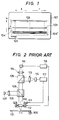
- Fig. 1 shows a plan view of such an optical card 101.
- Numeral 102 denotes an information record area
- numeral 103 denotes an information track
- numerals 104 and 104 ⁇ denote track select area
- numeral 105 denote a home position of a light beam spot.
- information is recorded as a line of optically detectable record bits (information track) by scanning the card by a light beam which is modulated by recording information and focused into a small spot.
- auto-tracking or AT an irradiation position of the light beam spot on the optical card in a direction normal to a scan direction.
- auto-focusing or AF the light beam spot in a direction normal to the optical card surface.
- the AT and AF are required in the reproduce mode.
- Fig. 2 shows a configuration of an apparatus for recording and reproducing information to and from the optical card.
- Numeral 106 denotes a motor for driving the optical card 101 in a direction of arrow
- numeral 107 denotes a light source such as a semiconductor laser
- numeral 108 denotes a collimator lens
- numeral 109 denotes a beam splitter
- numeral 110 denotes an objective lens
- numeral 111 denotes a tracking coil
- numeral 112 denotes a focusing coil
- numerals 113 and 114 denote condenser lenses
- numerals 115 and 116 denote photo-electric conversion elements
- numeral 117 denotes a tracking control circuit
- numeral 118 denotes a focusing control circuit.
- the light beam spot is initially at the home position 105.
- the light beam spot then moves on the track select area 104 in a direction u to find a record or reproduce track N, when the AT and AF are effected and the track N is scanned in a direction r to record or reproduce information.
- a large current is momentarily supplied to the tracking coil 111 (Fig. 2) so that the light beam spot is kicked to the track (N+1).
- the track (N+1) is scanned in the reverse direction l to record or reproduce information.
- the scan of the information track 103 by the light beam spot and the kick of the light beam spot in the track select areas 104 and 104 ⁇ are repeated several times.
- Fig. 3 illustrates such frequency dependency. It shows the dependency in the AT direction. It is assumed that the skew is ⁇ 100 ⁇ m. Assuming that the vibration in the AT direction is generated merely by the skew, the frequency dependency of the amplitude of the vibration in the AT direction is represented by a , at a frequency up to a reciprocation frequency fs when the light beam spot scans, the amplitude is flat at 100 ⁇ m, and above the frequency fs, the amplitude decreases at a rate of -12 dB/oct.
- the vibration in the AT direction is caused not only by the skew but also by the reversal of the reciprocal movement of the optical card.
- Such vibration occurs at a resonant frequency fp (fs ⁇ fp).
- fp fs ⁇ fp
- the vibration in the AT direction including the vibration at the reversal is represented by b in Fig. 3.
- the AT gain is raised as shown by ⁇ in Fig. 3.
- the AT is sufficiently attained at the reversal.
- the AT gain is higher than required, particularly in a high frequency band. Accordingly, the AT servo system is sensitive to a fine defect or dust on the surface of the optical card. This causes degradation of recorded or reproduced signal.
- the scan speed of the light beam spot in the direction and l direction differs between the record mode and the reproduce mode.
- a relatively low scan speed is selected by the limitation such as record sensitivity of the record medium.
- the speed V W in the record mode is lower than a speed V R in the reproduce mode (V W ⁇ V R ). Since the scan distance in the record m is equal to the scan distance in the reproduce mode, a frequency f w of the reciprocation in the scan in the record mode is lower than a scan frequency f R in the reproduce mode (f W ⁇ f R ).
- the amplitude is flat at 100 ⁇ m at a frequency up to the recording scan frequency 0.5 Hz, and it decreases at a rate of -12 dB/oct at a frequency above the scan frequency.
- the frequency dependency of the amplitude in the AT direction in the reproduce mode is represented by d .
- the amplitude is flat at 100 ⁇ m at a frequency up to the reproducing scan frequency 2.5 Hz, and it decreases at a rate of -12 dB/oct at a frequency above the scan frequency.
- US Patent 3474418 discloses a scanning system for reading data stored on memory elements and more particularly a scanning system utilising a light or an electron beam or the like for reading lines of data recorded on a recording element and employing a servo tracking control to maintain the beam in alignment with the data tracked.
- US Patent 3474418 discloses an apparatus having a means of detecting missing data areas along an information track and means of deactivating the said servo control in response to the detection of missing data thereby preventing said servo control from erroneously guiding said beam out of alignment with the desired data track.
- US 3474418 does not disclose an apparatus where applied servo gain is matched to the required servo gain due to increased frequency of vibration resulting from changes in velocity of scanning as disclosed in the present invention.
- WO85/01818 discloses an optical data storage and retrieval system comprising a data card having strips comprising microscopic data spots aligned in data cell positions on a grid in a lengthwise and widthwise directions.
- the said data may be optically read and as such a scanning optical recording and reading apparatus may be used.
- Such a reading/recording apparatus may be servo controlled.
- WO85/01818 discloses no apparatus suitable for applying a servo gain corresponding to the sero gain required due to the velocity of the said recording/reading apparatus with respect to the data card.
- an optical information recording and reproducing apparatus of the kind which has a light source, first optical means for guiding a light beam from the light source to a recording medium, second optical means for obtaining the light beam from the recording medium, optical detecting means for receiving the light beam obtained by the second optical means to output a focusing and/or tracking signal, adjusting means for adjusting a focusing (AF) and/or tracking (AT) operation of the light beam relative to the recording medium in accordance with the focusing and/or tracking signal output from the optical detecting means, reciprocating means for causing the recording medium to reciprocate, and a motor controller for controlling the reciprocating means, characterised in that means are provided to increase the servo gain of the focusing and/or tracking servo during a change in velocity of the recording means relative to the recording apparatus, so that the servo can cope with the higher frequency vibrations generated during the said change in velocity and the servo gain is higher during changes in velocity than during constant velocity.
- an optical information recording and reproducing apparatus of the kind which has a light source, first optical means for guiding a light beam from the light source to a recording medium, second optical means for obtaining the light beam from the recording medium, optical detecting means for receiving the light beam obtained by the second optical means to output a focusing and/or tracking signal, adjusting means for adjusting a focusing and/or tracking operation of the light beam relative to the recording medium in accordance with the focusing and/or tracking signal output from the optical detecting means, reciprocating means for causing the recording medium to reciprocate, and motor controller for controlling the reciprocating means, characterised in that means are provided to increase the servo gain of the focusing and/or tracking servo each time the direction of motion of the record medium is reversed so that the servo can cope with higher frequency vibrations generated at each reversal of the reciprocal movement.
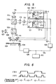
- Fig. 5 shows a configuration of an optical card recording and reproducing apparatus which is the optical information recording and reproducing apparatus of the present invention.
- the like elements to those shown in Fig. 2 are designated by the like numerals, and the explanation thereof is omitted.
- numerals 121 and 122 denote a tracking control circuit and a focusing control circuit, respectively.
- numeral 121-1 denotes an amplifier which amplifies an electrical tracking signal supplied from a photo-electric conversion element 115 to an appropriate voltage.
- Numeral 121-2 denotes an analog switch. Signal is supplied from the amplifier 121-1 through terminals C and D.
- Numeral 121-3 denotes a driver which receives the signal from the analog switch 121-2 to supply a drive signal current to a tracking coil 111.
- numeral 122-1 denotes an amplifier which amplifies an electrical focusing signal supplied from a photo-electric conversion element 116 to an appropriate voltage.
- Numeral 122-2 denotes an analog switch. The signal from the amplifier 122-1 is supplied thereto through terminals A and B.
- Numeral 122-3 denotes a driver which receives the signal from the analog switch 122-2 to supply a drive signal current to the focusing coil 112.
- numeral 123 denotes a system controller which controls the recording and reproducing apparatus
- numeral 124 denotes a signal produced by the controller to control the direction of movement of the optical card (i.e., the direction of rotation of a motor 106).
- the controller 123 also produces other signals than 124 although they are not shown.
- Numeral 125 denotes a motor driver which receives the signal 124 to control the direction of rotation of the motor 106.
- Numeral 126 denotes a one-shot multivibrator which receives the signal 124 to produce a signal 127 when the signal 124 transits.
- Fig. 6 shows a time chart showing a relation between the signals 124 and 127.
- pulse signals 127 having a width t are produced.
- the motor controller 125 starts the deceleration when the level of the signal 124 changes, stops the deceleration at the mid-point of the time period t, starts the acceleration in the opposite direction, and drives the motor at a steady speed at the mid-point of the time period t.
- the signal 127 is applied to the analog switches 121-2 and 122-2, which control the status of the switches.
- the pulse signal 127 is present (reversal)
- the terminal C of the switch 121-2 is closed and the terminal D is open.
- the terminal B is open.
- the pulse signal 127 is not present (non-reversal)
- the terminal C of the switch 121-2 is open and the terminal D is closed.
- the terminal A is open and the terminal B is closed. Accordingly, at the non-reversal time, the outputs from the amplifiers 121-1 and 122-1 are divided and they are supplied to the drivers 121-3 and 122-3, respectively.
- the output voltages from the amplifiers 121-1 and 122-1 are not divided and supplied to the drivers 121-3 and 122-3, respectively.
- the AT gain and AF gain at the reversal time can be higher than those at the non-reversal time.
- e shows the vibration in the AT direction only at the non-reversal time
- f shows the vibration in the AT direction including the reversal time.
- the AT gain is set to assume ⁇ shown in Fig. 7 at the reversal time (that is, when the output from the amplifier 121-1 is applied to the driver 121-3 through the terminal C).
- the output from the amplifier 121-1 is supplied to the driver 121-3 through the terminal D and the AT gain assumes ⁇ shown in Fig. 7 which is a shift-down version of ⁇ .
- the ⁇ may be set to be equal to ⁇ shown in Fig. 3 by appropriately selecting a resistance between the terminals C and D and other constants.
- the AT gain ⁇ at the reversal time is raised relative to the AT gain ⁇ at the non-reversal time. This is not absolutely necessary but it is sufficient to cover the vibration around the resonance frequency fp.
- the direction of relative reciprocal movement between the light beam spot and the information track of the optical information recording medium is switched and the tracking servo gain and/or focusing servo gain are also switched so that a minimum required gain is set for each circumstance.
- the degradation of the recorded and reproduced signals by the affect of defect or dust on the surface of the recording medium is prevented, and at the reversal time, the off-AT and off-AF are prevented. Accordingly, the reliability and error rate are improved.
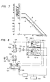
- Fig. 8 shows a configuration of another embodiment of the optical card recording and reproducing apparatus which is the optical information recording and reproducing apparatus of the present invention.
- the like elements to those shown in Fig. 5 are designated by the like numerals and the explanation thereof is omitted.
- numeral 123 denotes a system controller which controls the recording and reproducing apparatus
- numeral 134 denotes a record mode/reproduce mode select control signal produced by the controller.
- the controller l23 also produces signals other than 134 although they are not shown.
- Numeral 135 denotes a motor driver which receives the signal 134 to set the rotation speed of the motor 106 to the recording or reproducing speed.
- the signal 134 is applied to the analog switches 121-1 and 122-2 to control the status of the switches.
- the reproduce mode signal 134 is applied, the terminal C of the switch 121-2 is closed and the terminal D is open.
- the terminal A is closed and the terminal B is open.
- the record mode signal 134 is applied, the terminal C of the switch 121-2 is open and the terminal D is closed.
- the terminal A is open and the terminal B is closed. Accordingly, in the record mode, the output voltages from the amplifiers 121-1 and 122-1 are divided and they are supplied to the drivers 121-3 and 122-3.
- the output voltages from the amplifiers 121-1 and 122-1 are not divided and supplied to the drivers 121-3 and 122-3, respectively.
- the AT gain and AF gain in the record mode may be set lower than those in the reproduce mode.
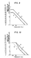
- Fig. 9 shows a graph of frequency characteristics of the amplitude of vibration in the AT direction and the AT gain.
- g represents a vibration in the AT direction in the record mode
- h represents a vibration in the AT direction in the reproduce mode. They are similar to c and d shown in Fig. 4.
- the AT gain in the record mode (that is, when the output of the amplifier 121-1 is applied to the driver 121-3 through the terminal D) is set to assume ⁇ of Fig. 9.
- the ⁇ is 60 dB at a frequency below the recording scan frequency 0.5 Hz and decreases at a rate of -12 dB/oct at a frequency above the scan frequency.
- the output of the amplifier 121-1 is applied to the driver 121-3 through the terminal C.
- the AT gain assumes ⁇ of Fig.
- the ⁇ is 60 dB at the reproducing scan frequency 2.5 Hz and decreases at a rate of -12 dB/oct at a frequency above the scan frequency.
- the AT gain ⁇ in the record mode is lower than the AT gain ⁇ in the reproduce mode.
- the AT gain in the record mode may be ⁇ which is lower than the AT gain in the reproduce mode only in the high frequency band.
- the speed of the relative reciprocal movement between the light beam spot and the information track of the optical information recording medium is switched, and the tracking servo gain and/or focusing servo gain are switched so that a minimum required gain is set for each circumstance. Accordingly, at the low speed, the degradation of signal by the affect of defect and dust on the surface of the recording medium due to overgain is prevented, and at the high speed, the off-AT and off-AF are prevented. Thus, the reliability and error rate are improved.
- the gain is electrically changed.
- the gain may be changed optically, mechanically or electrically, or by combination thereof, because the AT gain and AF gain are determined by the products of the electrical gain, optical gain and mechanical gain.
- the intensity of the light source 107 may be changed, an ND filter may be inserted into a light path, or a variable transmissibility ND filter may be used to change the transmissibility of the filter.
- the mechanical gain the number of turns of the tracking coil 111 may be changed or a distance between the tracking coil 111 and a magnet which is integral with the objective lens 110 may be changed.
Landscapes
- Optical Recording Or Reproduction (AREA)
Claims (3)
- Appareil d'enregistrement et de reproduction d'informations optiques du type qui comporte une source de lumière (107), des premiers moyens optiques (108, 109, 110) destines à guider un faisceau lumineux depuis la source de lumière jusqu'à un support d'enregistrement (101), des seconds moyens optiques (109, 113 à 116) destinés à obtenir le faisceau lumineux depuis le support d'enregistrement, des moyens de détection optiques (117, 118) destinés à recevoir le faisceau lumineux obtenu par les seconds moyens optiques pour délivrer en sortie un signal de mise au point et/ou de centrage, des moyens de réglage (111, 112) destines à régler une opération de mise au point (AF) et/ou de centrage (AT) du faisceau lumineux par rapport au support d'enregistrement (101) en fonction du signal de mise au point et/ou de centrage délivré en sortie par les moyens de détection optiques, des moyens (106) à mouvement alternatif destinés à provoquer un mouvement alternatif du support d'enregistrement (101), et un dispositif (125) de commande à moteur destiné à commander les moyens (106) à mouvement alternatif,
caractérisé en ce que des moyens (121, 122, 123 et 126) sont prévus pour augmenter le gain d'asservissement de l'asservissement de mise au point et/ou centrage durant une variation de la vitesse des moyens d'enregistrement par rapport à l'appareil d'enregistrement, de façon que l'asservissement puisse faire face aux vibrations de fréquence plus élevées générées durant ladite variation de vitesse et que le gain de l'asservissement soit plus élevé durant des variations de vitesse que durant une vitesse constante. - Appareil d'enregistrement et de reproduction d'informations optiques du type qui comporte une source de lumière (107), des premiers moyens optiques (108, 109, 110) destinés à guider un faisceau lumineux depuis la source de lumière jusqu'à un support d'enregistrement (101), des seconds moyens optiques (109, 113 à 116) destinés à obtenir le faisceau lumineux provenant du support d'enregistrement, des moyens de détection optiques (117, 118) destinés à recevoir le faisceau lumineux obtenu par les seconds moyens optiques pour délivrer en sortie un signal de mise au point et/ou centrage, des moyens de réglage (111, 112) destinés à régler une opération de mise au point et/ou centrage du faisceau lumineux par rapport au support d'enregistrement (101) en fonction du signal de mise au point et/ou de centrage délivré en sortie par les moyens de détection optiques, des moyens (106) à mouvement alternatif destinés à provoquer un mouvement alternatif du support d'enregistrement, et un dispositif (125) de commande à moteur destiné à commander les moyens (106) à mouvement alternatif,
caractérisé en ce que des moyens (121, 122, 123, 126) sont prévus pour augmenter le gain d'asservissement de l'asservissement de mise au point et/ou centrage à chaque fois que le sens du mouvement du support d'enregistrement est inversé afin que l'asservissement puisse faire face à des vibrations de fréquence plus élevée générées à chaque inversion du mouvement alternatif. - Appareil d'enregistrement et de reproduction d'informations optiques selon la revendication 1, dans lequel lesdits moyens (121, 122, 123, 126) d'établissement du gain établissent le gain sur la base d'un signal de sortie dudit moyen (123) de commande.
Applications Claiming Priority (4)
| Application Number | Priority Date | Filing Date | Title |
|---|---|---|---|
| JP113512/86 | 1986-05-20 | ||
| JP61113512A JPH079706B2 (ja) | 1986-05-20 | 1986-05-20 | 光学的情報記録再生装置 |
| JP113511/86 | 1986-05-20 | ||
| JP11351186A JPS62271230A (ja) | 1986-05-20 | 1986-05-20 | 光学的情報記録再生装置 |
Publications (3)
| Publication Number | Publication Date |
|---|---|
| EP0246830A2 EP0246830A2 (fr) | 1987-11-25 |
| EP0246830A3 EP0246830A3 (en) | 1989-03-15 |
| EP0246830B1 true EP0246830B1 (fr) | 1992-08-05 |
Family
ID=26452465
Family Applications (1)
| Application Number | Title | Priority Date | Filing Date |
|---|---|---|---|
| EP87304349A Expired EP0246830B1 (fr) | 1986-05-20 | 1987-05-15 | Appareil d'enregistrement et de reproduction d'informations optiques |
Country Status (4)
| Country | Link |
|---|---|
| US (1) | US4888756A (fr) |
| EP (1) | EP0246830B1 (fr) |
| CA (1) | CA1301324C (fr) |
| DE (1) | DE3780866T2 (fr) |
Families Citing this family (15)
| Publication number | Priority date | Publication date | Assignee | Title |
|---|---|---|---|---|
| US4906874A (en) * | 1988-01-22 | 1990-03-06 | Sharp Kabushiki Kaisha | Analog signal switching device for use in an optical memory |
| US5029151A (en) * | 1988-02-17 | 1991-07-02 | Canon Kabushiki Kaisha | Optical information processing apparatus including a limiter for limiting error of focusing and/or tracking actuators and a circuit for adjusting the limit range thereof |
| US5341355A (en) * | 1988-05-20 | 1994-08-23 | Ricoh Company, Ltd. | Multibeam optical pickup and servo method thereof |
| JP2904434B2 (ja) * | 1988-08-12 | 1999-06-14 | パイオニア株式会社 | 光学式情報記録媒体及びその再生装置 |
| JP2706301B2 (ja) * | 1989-02-15 | 1998-01-28 | キヤノン株式会社 | 光学的情報記録再生装置 |
| JPH02247830A (ja) * | 1989-03-20 | 1990-10-03 | Pioneer Electron Corp | サーボループのループゲイン設定方法 |
| JPH03100931A (ja) * | 1989-09-14 | 1991-04-25 | Mitsubishi Electric Corp | 光学式情報記録再生装置 |
| JP2723646B2 (ja) * | 1990-03-27 | 1998-03-09 | キヤノン株式会社 | 光学的情報処理装置 |
| JP2531847B2 (ja) * | 1990-09-27 | 1996-09-04 | インターナシヨナル・ビジネス・マシーンズ・コーポレーシヨン | 光学ディスク駆動装置 |
| GB2248989B (en) * | 1990-10-15 | 1995-05-24 | Applied Magnetics Corp | Focus sensing apparatus and method |
| JP2954404B2 (ja) * | 1991-10-09 | 1999-09-27 | 株式会社日本コンラックス | 光学的情報記録再生装置 |
| US5257252A (en) * | 1991-12-18 | 1993-10-26 | Hewlett-Packard Company | Adaptive control system for a disk drive actuator |
| US6371370B2 (en) * | 1999-05-24 | 2002-04-16 | Agilent Technologies, Inc. | Apparatus and method for scanning a surface |
| JP3824135B2 (ja) * | 2001-01-10 | 2006-09-20 | 横河電機株式会社 | バイオチップ読取り装置 |
| CN105637527B (zh) * | 2013-10-29 | 2017-12-05 | 美国索尼公司 | 光学介质的阵列读取器和阵列读取 |
Family Cites Families (13)
| Publication number | Priority date | Publication date | Assignee | Title |
|---|---|---|---|---|
| US3474418A (en) * | 1967-06-19 | 1969-10-21 | Ibm | Data tracking system |
| JPS626580Y2 (fr) * | 1979-11-17 | 1987-02-16 | ||
| JPS58166567A (ja) * | 1982-03-26 | 1983-10-01 | Matsushita Electric Ind Co Ltd | 情報トラックの検索装置 |
| JPS59116939A (ja) * | 1982-12-23 | 1984-07-06 | Olympus Optical Co Ltd | 光学式記録再生装置 |
| NL8300844A (nl) * | 1983-03-09 | 1984-10-01 | Philips Nv | Inrichting voor het uitlezen van een optisch gekodeerde schijfvormige registratiedrager. |
| JPS59198537A (ja) * | 1983-04-22 | 1984-11-10 | Matsushita Electric Ind Co Ltd | 光学的記録再生装置 |
| NL8303029A (nl) * | 1983-08-31 | 1985-03-18 | Philips Nv | Inrichting voor het uitlezen van een schijfvormige optische registratiedrager. |
| JP2719549B2 (ja) * | 1983-10-12 | 1998-02-25 | ドレクスラ−・テクノロジ−・コ−ポレ−ション | 4倍密度光学データシステム |
| US4634850A (en) * | 1983-10-12 | 1987-01-06 | Drexler Technology Corporation | Quad density optical data system |
| US4734565A (en) * | 1983-10-12 | 1988-03-29 | Drexler Technology Corporation | Read-only optical card and system |
| US4598393A (en) * | 1984-04-06 | 1986-07-01 | Drexler Technology Corporation | Three-beam optical servo tracking system with two-track parallel readout |
| FR2575578B1 (fr) * | 1984-12-31 | 1995-03-03 | Canon Kk | Appareil d'enregistrement et de reproduction optiques d'informations |
| JPH0664632B2 (ja) * | 1985-09-06 | 1994-08-22 | キヤノン株式会社 | 情報記録再生装置 |
-
1987
- 1987-05-15 CA CA000537266A patent/CA1301324C/fr not_active Expired - Lifetime
- 1987-05-15 EP EP87304349A patent/EP0246830B1/fr not_active Expired
- 1987-05-15 DE DE8787304349T patent/DE3780866T2/de not_active Expired - Fee Related
-
1988
- 1988-12-30 US US07/291,368 patent/US4888756A/en not_active Expired - Lifetime
Also Published As
| Publication number | Publication date |
|---|---|
| DE3780866T2 (de) | 1993-03-18 |
| EP0246830A2 (fr) | 1987-11-25 |
| US4888756A (en) | 1989-12-19 |
| DE3780866D1 (de) | 1992-09-10 |
| CA1301324C (fr) | 1992-05-19 |
| EP0246830A3 (en) | 1989-03-15 |
Similar Documents
| Publication | Publication Date | Title |
|---|---|---|
| EP0246830B1 (fr) | Appareil d'enregistrement et de reproduction d'informations optiques | |
| EP0256827B1 (fr) | Appareil d'enregistrement et de reproduction de données sur disque optique | |
| US5909414A (en) | Optical information recording and reproducing apparatus having a function of preventing overwrite recording | |
| US5146442A (en) | Method and apparatus for effecting at least one of tracking and servo control when an error signal passes a zero-cross point and reaches a predetermined non-zero value | |
| CA1301925C (fr) | Appareil d'enregistrement et de lecture optiques d'informations | |
| US5099468A (en) | Optical information processing apparatus having offset adjusting circuit which can be exchanged together with optical head | |
| US5138596A (en) | Optical information recording apparatus including means for delaying servo gain by a predetermined time | |
| US5475660A (en) | Optical information recording-reproducing method and apparatus including focusing and/or tracking control depending on a determined state of an optical spot | |
| US5029151A (en) | Optical information processing apparatus including a limiter for limiting error of focusing and/or tracking actuators and a circuit for adjusting the limit range thereof | |
| JPH04176025A (ja) | 光学ヘッド | |
| US5200937A (en) | Apparatus for and method of recording and/or reproducing information by means of two actuators | |
| EP0326343A2 (fr) | Appareil optique d'enregistrement d'information | |
| US5371725A (en) | Position control system for a read-write head of a magneto-optical disc player having heads which move independently from each other | |
| JPH05182224A (ja) | 光ディスク装置 | |
| JP2592794B2 (ja) | 光学的情報記録再生方法 | |
| US4785440A (en) | Method and apparatus for driving an optical pickup of an optical information recording and reproducing apparatus | |
| JPH079706B2 (ja) | 光学的情報記録再生装置 | |
| JP2956106B2 (ja) | 光学的情報記録方法 | |
| EP0383562B1 (fr) | Appareil pour l'enregistrement et/ou la reprocuction d'information optique avec dispositif pour interdire le mouvement de la tête optique | |
| JPH0546616B2 (fr) | ||
| KR100628184B1 (ko) | 광 기록재생기의 액츄에이터 제어 장치 | |
| JP2536875B2 (ja) | 情報記録再生装置 | |
| JPS62271230A (ja) | 光学的情報記録再生装置 | |
| JPH0682468B2 (ja) | 光学的情報記録再生装置 | |
| JPH0727638B2 (ja) | 光学的情報記録再生方法 |
Legal Events
| Date | Code | Title | Description |
|---|---|---|---|
| PUAI | Public reference made under article 153(3) epc to a published international application that has entered the european phase |
Free format text: ORIGINAL CODE: 0009012 |
|
| AK | Designated contracting states |
Kind code of ref document: A2 Designated state(s): DE FR GB IT NL |
|
| PUAL | Search report despatched |
Free format text: ORIGINAL CODE: 0009013 |
|
| AK | Designated contracting states |
Kind code of ref document: A3 Designated state(s): DE FR GB IT NL |
|
| 17P | Request for examination filed |
Effective date: 19890809 |
|
| 17Q | First examination report despatched |
Effective date: 19900516 |
|
| GRAA | (expected) grant |
Free format text: ORIGINAL CODE: 0009210 |
|
| AK | Designated contracting states |
Kind code of ref document: B1 Designated state(s): DE FR GB IT NL |
|
| ET | Fr: translation filed | ||
| REF | Corresponds to: |
Ref document number: 3780866 Country of ref document: DE Date of ref document: 19920910 |
|
| ITF | It: translation for a ep patent filed | ||
| PLBE | No opposition filed within time limit |
Free format text: ORIGINAL CODE: 0009261 |
|
| STAA | Information on the status of an ep patent application or granted ep patent |
Free format text: STATUS: NO OPPOSITION FILED WITHIN TIME LIMIT |
|
| 26N | No opposition filed | ||
| ITTA | It: last paid annual fee | ||
| PGFP | Annual fee paid to national office [announced via postgrant information from national office to epo] |
Ref country code: GB Payment date: 20010501 Year of fee payment: 15 |
|
| PGFP | Annual fee paid to national office [announced via postgrant information from national office to epo] |
Ref country code: DE Payment date: 20010516 Year of fee payment: 15 |
|
| PGFP | Annual fee paid to national office [announced via postgrant information from national office to epo] |
Ref country code: FR Payment date: 20010517 Year of fee payment: 15 |
|
| PGFP | Annual fee paid to national office [announced via postgrant information from national office to epo] |
Ref country code: NL Payment date: 20010531 Year of fee payment: 15 |
|
| REG | Reference to a national code |
Ref country code: GB Ref legal event code: IF02 |
|
| PG25 | Lapsed in a contracting state [announced via postgrant information from national office to epo] |
Ref country code: GB Free format text: LAPSE BECAUSE OF NON-PAYMENT OF DUE FEES Effective date: 20020515 |
|
| PG25 | Lapsed in a contracting state [announced via postgrant information from national office to epo] |
Ref country code: NL Free format text: LAPSE BECAUSE OF NON-PAYMENT OF DUE FEES Effective date: 20021201 |
|
| PG25 | Lapsed in a contracting state [announced via postgrant information from national office to epo] |
Ref country code: DE Free format text: LAPSE BECAUSE OF NON-PAYMENT OF DUE FEES Effective date: 20021203 |
|
| GBPC | Gb: european patent ceased through non-payment of renewal fee |
Effective date: 20020515 |
|
| PG25 | Lapsed in a contracting state [announced via postgrant information from national office to epo] |
Ref country code: FR Free format text: LAPSE BECAUSE OF NON-PAYMENT OF DUE FEES Effective date: 20030131 |
|
| NLV4 | Nl: lapsed or anulled due to non-payment of the annual fee |
Effective date: 20021201 |
|
| REG | Reference to a national code |
Ref country code: FR Ref legal event code: ST |
|
| PG25 | Lapsed in a contracting state [announced via postgrant information from national office to epo] |
Ref country code: IT Free format text: LAPSE BECAUSE OF NON-PAYMENT OF DUE FEES;WARNING: LAPSES OF ITALIAN PATENTS WITH EFFECTIVE DATE BEFORE 2007 MAY HAVE OCCURRED AT ANY TIME BEFORE 2007. THE CORRECT EFFECTIVE DATE MAY BE DIFFERENT FROM THE ONE RECORDED. Effective date: 20050515 |