EP0246548B1 - Verfahren zur Herstellung eines Entladungsgefässes für kompakte Niederdruckentladungslampen - Google Patents
Verfahren zur Herstellung eines Entladungsgefässes für kompakte Niederdruckentladungslampen Download PDFInfo
- Publication number
- EP0246548B1 EP0246548B1 EP87106881A EP87106881A EP0246548B1 EP 0246548 B1 EP0246548 B1 EP 0246548B1 EP 87106881 A EP87106881 A EP 87106881A EP 87106881 A EP87106881 A EP 87106881A EP 0246548 B1 EP0246548 B1 EP 0246548B1
- Authority
- EP
- European Patent Office
- Prior art keywords
- tube
- glass tube
- bend
- heated
- glass
- Prior art date
- Legal status (The legal status is an assumption and is not a legal conclusion. Google has not performed a legal analysis and makes no representation as to the accuracy of the status listed.)
- Expired - Lifetime
Links
- 238000000034 method Methods 0.000 title claims description 29
- 239000011521 glass Substances 0.000 claims description 54
- 238000010438 heat treatment Methods 0.000 claims description 9
- 238000005452 bending Methods 0.000 claims description 8
- 238000004519 manufacturing process Methods 0.000 claims description 8
- 238000007664 blowing Methods 0.000 claims description 3
- 230000015572 biosynthetic process Effects 0.000 claims 1
- 238000007906 compression Methods 0.000 description 6
- 230000006835 compression Effects 0.000 description 5
- 230000007423 decrease Effects 0.000 description 3
- 238000005516 engineering process Methods 0.000 description 3
- 230000005484 gravity Effects 0.000 description 3
- 238000001816 cooling Methods 0.000 description 2
- 239000004753 textile Substances 0.000 description 2
- 239000000835 fiber Substances 0.000 description 1
- 238000007380 fibre production Methods 0.000 description 1
- QSHDDOUJBYECFT-UHFFFAOYSA-N mercury Chemical compound [Hg] QSHDDOUJBYECFT-UHFFFAOYSA-N 0.000 description 1
- 229910052751 metal Inorganic materials 0.000 description 1
- 239000002184 metal Substances 0.000 description 1
- 230000001105 regulatory effect Effects 0.000 description 1
- 230000004584 weight gain Effects 0.000 description 1
- 235000019786 weight gain Nutrition 0.000 description 1
Images

Classifications
-
- C—CHEMISTRY; METALLURGY
- C03—GLASS; MINERAL OR SLAG WOOL
- C03B—MANUFACTURE, SHAPING, OR SUPPLEMENTARY PROCESSES
- C03B23/00—Re-forming shaped glass
- C03B23/04—Re-forming tubes or rods
- C03B23/049—Re-forming tubes or rods by pressing
- C03B23/0493—Re-forming tubes or rods by pressing in a longitudinal direction, e.g. for upsetting or extrusion
-
- C—CHEMISTRY; METALLURGY
- C03—GLASS; MINERAL OR SLAG WOOL
- C03B—MANUFACTURE, SHAPING, OR SUPPLEMENTARY PROCESSES
- C03B23/00—Re-forming shaped glass
- C03B23/04—Re-forming tubes or rods
- C03B23/06—Re-forming tubes or rods by bending
-
- C—CHEMISTRY; METALLURGY
- C03—GLASS; MINERAL OR SLAG WOOL
- C03B—MANUFACTURE, SHAPING, OR SUPPLEMENTARY PROCESSES
- C03B23/00—Re-forming shaped glass
- C03B23/04—Re-forming tubes or rods
- C03B23/06—Re-forming tubes or rods by bending
- C03B23/065—Re-forming tubes or rods by bending in only one plane, e.g. for making circular neon tubes
-
- C—CHEMISTRY; METALLURGY
- C03—GLASS; MINERAL OR SLAG WOOL
- C03B—MANUFACTURE, SHAPING, OR SUPPLEMENTARY PROCESSES
- C03B23/00—Re-forming shaped glass
- C03B23/04—Re-forming tubes or rods
- C03B23/07—Re-forming tubes or rods by blowing, e.g. for making electric bulbs
-
- Y—GENERAL TAGGING OF NEW TECHNOLOGICAL DEVELOPMENTS; GENERAL TAGGING OF CROSS-SECTIONAL TECHNOLOGIES SPANNING OVER SEVERAL SECTIONS OF THE IPC; TECHNICAL SUBJECTS COVERED BY FORMER USPC CROSS-REFERENCE ART COLLECTIONS [XRACs] AND DIGESTS
- Y02—TECHNOLOGIES OR APPLICATIONS FOR MITIGATION OR ADAPTATION AGAINST CLIMATE CHANGE
- Y02B—CLIMATE CHANGE MITIGATION TECHNOLOGIES RELATED TO BUILDINGS, e.g. HOUSING, HOUSE APPLIANCES OR RELATED END-USER APPLICATIONS
- Y02B20/00—Energy efficient lighting technologies, e.g. halogen lamps or gas discharge lamps
Definitions
- the invention relates to a method for producing a single or multiple curved tubular discharge vessel for a compact low-pressure discharge lamp in accordance with the preamble of claim 1.
- DE-OS 3 005 052 discloses a method for producing a multi-curved tubular discharge vessel for electric discharge lamps. To produce the bends, an essentially straight glass tube is heated until it softens at the corresponding points and the tube is bent around a shaped body at the heated points by correspondingly pivoting the unheated parts.
- EP-PS 61 758 also describes a method for producing a single or multiple-curved tubular discharge vessel for a low-pressure mercury vapor discharge lamp.
- the tube parts of a straight glass tube to be bent are brought to the softening temperature and a 180 ° bend is created by bending the adjacent tube parts against each other.
- the 180 ° bend is then placed in a shaped body and a U-shaped bend corresponding to the shaped body with substantially rectangular corners is produced by blowing compressed air into the pipe ends.
- the right-angled corners serve as a cooling point for optimal lamp operation.
- a disadvantage of the production of the 180 ° bends is that the wall thickness of the glass tube on the outer lateral surface of the bend decreases due to the bending process. This decrease is further increased when creating 180 ° bends with essentially rectangular corners. Because of the thin wall, the discharge vessels at these points are particularly prone to breakage.
- the distribution of the glass is particularly critical if the 180 ° bend in the area of the apex is to have an inner diameter which is larger than the diameter of the original straight glass tube. Such arches are required in particular for compact, low-pressure discharge lamps with high loads.
- the risk of breakage can be prevented by using a glass tube with a correspondingly large wall diameter in the manufacture of the discharge vessel, so that after the 180 ° bends have been created, the glass wall on the outer lateral surface does not fall below a certain minimum wall thickness. As a result, however, a considerable increase in the weight of the vessel and thus the lamp and an increase in costs are accepted.
- glass tubes are known as guide aids in textile fiber production.
- the funnel-shaped tubes have constrictions that protrude inwards, which ensure that the textile fibers are centered in the axis of the tube. Since the constrictions make the tubes very fragile, it is proposed to increase the thickness of the glass wall by compressing the tube in the region of the constrictions.
- the aim of the invention is to find a method for producing a single or multiple curved discharge vessel made of glass, although despite the use of a straight glass tube with a wall thickness, as is sufficient for the straight tube parts, also in the areas of the bends where the Bending radius is greatest, a certain minimum wall thickness is not undershot.
- the method should not involve any significant weight gain in the discharge vessel.
- the tube wall is reinforced at the points where a 180 ° bend is provided by the compression of the discharge vessel. A much more targeted distribution of the glass in the area of the bend can be achieved if the glass is heated more strongly in the two edge areas of the pipe section required for the bend than in the middle area in between.
- the easiest way to achieve compression is to rotate the glass tube around its longitudinal axis during the heating and upsetting process. If, on the other hand, the glass tube is not rotated during the heating and upsetting process, the glass can be increasingly distributed downwards due to gravity. The tube must then be bent so that the amount of glass collected at the bottom of the tube is used to form the outer surface. In this way, with the amount of glass accumulated on the bottom, it is also possible to create wide arches with right-angled corners without having to accept a decrease in the wall thickness of the glass tube in the bend. Such an implementation is more complex in terms of process technology and in particular requires special flame technology and controlled blown air.
- the bend is given a corresponding shape in a special process step and the corners are created by blowing compressed air into the pipe ends.
- the right-angled corners serve as cooling points in the finished discharge vessel, through which the vapor pressure in the vessel and thus the light output is regulated.
- FIGS. 1a to 1e The method is illustrated in more detail with the aid of two different process sequences, FIGS. 1a to 1e and FIGS. 2a to 2e.
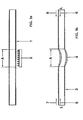
- FIGS. 1 a to 1 e show the individual process steps for producing a simply curved tubular discharge vessel with essentially rectangular corners.
- the tube section A of a straight glass tube 1 required for the 180 ° bend is first heated using a gas burner 2 until it softens.
- the glass tube like heating, is not rotated, which, as shown below, has advantages in terms of the thickness of the glass wall during the bending process.
- the glass tube 3 is constricted in the heated section A 4.
- Air is then blown into the two ends of the glass tube - indicated by the two arrows 5 and 6 labeled L - and at the same time the ends in the direction the two arrows 7 and 8 moved against each other, so that the glass tube is compressed at the constricted point 4.
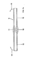
- the glass tube 9 is shown after upsetting.
- the glass In the area of the compression there is an uneven distribution of the glass, because due to the force of gravity, the glass has increasingly run downwards during the heating in the first process step.
- the amount of glass 10 accumulated on the bottom of the tube 9 is thus greater than that on the wall 11 lying at the top.
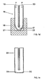
- the bent glass tube 16 with the 180 ° bend 17 is brought into a shaped body 18 made of metal.
- the glass tube 16 is blown into the right-angled corners 21 and 22 of the shaped body 18 by means of compressed air, which is conveyed into the two ends of the bent glass tube 16, illustrated by the arrows 19 and 20 denoted by P.
- FIG. 1e shows the completely shaped discharge vessel 23 with a 180 ° bend and two essentially rectangular corners 24, 25.
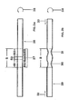
- FIGS. 2a to 2d show somewhat modified method steps for producing a compression on a straight glass tube.
- the glass tube 26 is heated - according to FIG. 2a - in the section B required for a 180 ° bend by a burner 27 with an uneven flame distribution until it softens.
- the heating is stronger in the two edge areas B1 and B 2 than in the area B3 in between.
- a burner with an uneven flame distribution it is also possible to use several different burners which are at a certain distance from one another.
- the tube 26 is rotated about its axis - illustrated by the curved arrow 28 - in order to obtain a heating that is as uniform as possible over the circumference.
- the glass tube 29 is provided with two constrictions 30, 31 in the heated tube section B which are at a small distance from one another. Then the ends of the tube 29 are moved towards each other in the direction of the two arrows 32, 33, so that the tube 29 undergoes compression at the constricted points 30, 31, the tube being rotated about its axis in order to achieve great uniformity during the compression process - see arrow 34.
- FIG. 2c shows the glass tube 35 with the two thickened regions 36, 37 after the upsetting process.
- the glass tube 35 now experiences a uniform heating, with no more rotation about its own axis.
- the glass runs downward due to gravity, so that, as shown in FIG. 2d, the amount of glass 39 accumulated at the bottom of the glass tube 38 is greater than the amount 40 remaining at the upper edge.
- the two straight tube sections 41, 42 laterally from the compressed area are now bent upwards - according to the arrows 43, 44 - so that a 180 ° bend is produced.
- the further process steps for producing a 180 ° bend with right-angled corners correspond to the sequences shown in FIGS. 1 d and 1 e.
Landscapes
- Chemical & Material Sciences (AREA)
- Engineering & Computer Science (AREA)
- Materials Engineering (AREA)
- Organic Chemistry (AREA)
- Manufacture Of Electron Tubes, Discharge Lamp Vessels, Lead-In Wires, And The Like (AREA)
- Re-Forming, After-Treatment, Cutting And Transporting Of Glass Products (AREA)
Description
- Die Erfindung betrifft ein Verfahren zur Herstellung eines ein- oder mehrfach gebogenen rohrförmigen Entladungsgefäßes für eine kompakte Niederdruckentladungslampe entsprechend dem Oberbegriff des Anspruchs 1.
- Aus der DE-OS 3 005 052 ist ein Verfahren zur Herstellung eines mehrfach gebogenen rohrförmigen Entladungsgefäßes für elektrische Entladungslampen bekannt. Zur Herstellung der Biegungen wird dazu ein im wesentlichen gerades Glasrohr an den entsprechenden Stellen bis zum Erweichen erhitzt und durch entsprechendes Schwenken der nicht erhitzten Teile das Rohr an den erhitzten Stellen um einen Formkörper herumgebogen.
- Auch in der EP-PS 61 758 wird ein Verfahren zur Herstellung eines ein- oder mehrfach gebogenen rohrförmigen Entladungsgefäßes für eine Quecksilberdampf-Niederdruckentladungslampe beschrieben. Die zu biegenden Rohrteile eines geraden Glasrohres werden auf Erweichungstemperatur gebracht und durch Gegeneinanderbiegen der benachbarten Rohrteile eine 180°-Biegung erstellt. Anschließend wird die 180°-Biegung in einen Formkörper gegeben und durch Einblasen von Druckluft in die Rohrenden eine dem Formkörper entsprechende U-förmige Biegung mit im wesentlichen rechtwinkligen Ecken hergestellt. Die rechtwinkligen Ecken dienen dabei als Kühlstelle für den optimalen Betrieb der Lampe.
- Als nachteilig erweist sich bei der Herstellung der 180°-Biegungen, daß die Wanddicke des Glasrohres an der äußeren Mantelfläche der Biegung durch den Biegevorgang abnimmt. Bei der Erstellung von 180°-Biegungen mit im wesentlichen rechtwinkligen Ecken wird diese Abnahme noch weiter verstärkt. Aufgrund der dünnen Wand sind daher die Entladungsgefäße an diesen Stellen besonders bruchgefährdet.
- Besonders kritisch ist die Verteilung des Glases, wenn die 180°-Biegung im Bereich des Scheitels einen Innendurchmesser aufweisen soll, der größer als der Durchmesser des ursprünglichen geraden Glasrohres ist. Solchermaßen gestaltete Bögen werden insbesondere für kompakte Niederdruckentladungslampen mit hoher Belastung benötigt.
- Die Bruchgefährdung kann verhindert werden, indem bei der Herstellung des Entladungsgefäßes ein Glasrohr mit einem entsprechend großen Wanddurchmesser verwendet wird, so daß nach Erstellung der 180°-Biegungen die Glaswand an der äußeren Mantelfläche eine gewisse Mindestwanddicke nicht unterschreitet. Dadurch wird jedoch eine erhebliche Gewichtszunahme des Gefäßes und damit der Lampe sowie eine Kostensteigerung in Kauf genommen.
- Aus der US-PS 1 948 560 sind Glasröhrchen als Führungshilfen bei der Textilfaserherstellung bekannt. Die trichterförmig ausgebildeten Röhrchen weisen nach innen ragende Einschnürungen auf, die für die Zentrierung der Textilfaser in der Achse des Röhrchens sorgen. Da durch die Einschnürungen die Röhrchen stark bruchgefährdet sind, wird vorgeschlagen durch Stauchen des Röhrchens im Bereich der Einschnürungen die Dicke der Glaswand zu erhöhen.
- Ziel der Erfindung ist es, ein Verfahren zur Herstellung eines ein- oder mehrfach gebogenen Entladungsgefäßes aus Glas zu finden, wobei trotz Verwendung eines geraden Glasrohres mit einer Wanddicke, wie sie für die geraden Rohrteile ausreichend ist, auch in den Bereichen der Biegungen, wo der Biegeradius am größten ist, eine gewisse Mindestwandstärke nicht unterschritten wird. Insbesondere soll mit dem Verfahren keine wesentliche Gewichtszunahme beim Entladungsgefäß verbunden sein.
- Das Ziel wird durch einen Verfahrensschritt entsprechend dem kennzeichnenden Merkmal des 1. Anspruchs gelöst. Weitere vorteilhafte Verfahrensschritte sind den Unteransprüchen zu entnehmen.
- Durch die Stauchung des Entladungsgefäßes wird an den Stellen, an denen eine 180°-Biegung vorgesehen ist, die Rohrwand verstärkt. Eine wesentlich gezieltere Verteilung des Glases im Bereich der Biegung läßt sich erreichen, wenn das Glas in den beiden Randbereichen des für die Biegung benötigten Rohrabschnitts stärker als in dem dazwischenliegenden Mittelbereich erwärmt wird.
- Bei Glasrohren mit geringen Wanddicken ist es erforderlich, daß während des Stauchvorganges mit Hilfe von Blasluft im Glasrohr ein geringer Überdruck erzeugt wird. Dadurch wird ein Zusammenfallen des Glasrohres im Stauchbereich verhindert und einer Verkleinerung des Innendurchmessers vorgebeugt.
- Vom glastechnischen Standpunkt kann die Stauchung am einfachsten realisiert werden, wenn das Glasrohr während des Erwärmungs- und Stauchvorganges um seine Längsachse rotiert. Wird dagegen das Glasrohr während des Erwärmungs- und Stauchvorganges nicht gedreht, so läßt sich das Glas aufgrund der Schwerkraft verstärkt nach unten verteilen. Die Biegung des Rohres ist dann so vorzunehmen, daß die am Boden des Glasrohres angesammelte Glasmenge zur Bildung der äußeren Mantelfläche verwendet wird. Auf diese Weise lassen sich mit der am Boden angesammelten Glasmenge auch weite Bögen mit rechtwinkligen Ecken erstellen, ohne daß eine Abnahme der Wandstärke des Glasrohres in der Biegung in Kauf genommen werden muß. Eine solche Durchführung ist verfahrenstechnisch aufwendiger und erfordert insbesondere eine besondere Flammentechnik und gesteuerte Blasluft.
- Zur Herstellung der rechtwinkligen Ecken an der 180°-Biegung wird die Biegung in einem speziellen Verfahrensschritt in eine entsprechende Form gegeben und die Ecken durch Einblasen von Druckluft in die Rohrenden erzeugt. Die rechtwinkligen Ecken dienen beim fertigen Entladungsgefäß als Kühlstellen, durch die der Dampfdruck im Gefäß und damit die Lichtausbeute geregelt wird.
- Das Verfahren ist anhand von zwei unterschiedlichen Verfahrensabläufen Figur 1a bis 1 e und Figur 2a bis 2e näher veranschaulicht.
- Figuren 1 a bis 1 e zeigen die einzelnen Verfahrensschritte zur Herstellung eines einfach gebogenen rohrförmigen Entladungsgefäßes mit im wesentlichen rechtwinkligen Ecken. Zur Herstellung wird zuerst, wie in Figur 1a dargestellt, der für die 180°-Biegung benötigte Rohrabschnitt A eines geraden Glasrohres 1 mit Hilfe eines Gasbrenners 2 bis zur Erweichung erwärmt. Das Glasrohr wird wie der Erwärmung nicht gedreht, was, wie unten aufgezeigt, Vorteile in bezug auf die Dicke der Glaswand beim Biegevorgang hat. Das Glasrohr 3 erhält, wie in Figur 1 b gezeigt, in dem erwärmten Abschnitt A eine Einschnürung 4. In die beiden Enden des Glasrohres wird anschließend Luft geblasen - durch die beiden mit L bezeichneten Pfeile 5 und 6 angedeutet - und gleichzeitig die Enden in Richtung der beiden Pfeile 7 und 8 gegeneinander bewegt, so daß an der eingeschnürten Stelle 4 das Glasrohr gestaucht wird.
- In Figur 1 ist das Glasrohr 9 nach dem Stauchen wiedergegeben. Im Bereich der Stauchung ergibt sich eine ungleichmäßige Verteilung des Glases, da aufgrund der Schwerkraft das Glas bei der Erwärmung im ersten Verfahrensschritt verstärkt nach unten gelaufen ist. Die am Boden des Rohres 9 angesammelte Glasmenge 10 ist somit größer als die an der oben liegenden Wandung 11. Durch Gegeneinanderbiegen der seitlich von dem gestauchten Bereich befindlichen geraden Rohrabschnitte 12, 13 nach oben - entsprechend den Pfeilen 14 und 15 - wird nun eine 180°-Biegung erzeugt. Der Biegevorgang wird nach oben ausgeführt, damit die größere Glasmenge 10 am Boden des Rohres 9 zur Bildung der äußeren Mantelfläche an der 180°-Biegung zur Verfügung steht.
- Anschließend wird - wie in Figur 1d dargestellt - das gebogene Glasrohr 16 mit der 180°-Biegung 17 in einen Formkörper 18 aus Metall gebracht. Mittels Preßluft, die - veranschaulicht durch die mit P bezeichneten Pfeile 19 und 20 - in die beiden Enden des gebogenen Glasrohres 16 befördert wird, wird das Glasrohr 16 in die rechtwinkligen Ecken 21 und 22 des Formkörpers 18 geblasen
- In Figur 1e ist das fertig geformte Entladungsgefäß 23 mit einer 180°-Biegung und zwei im wesentlichen rechtwinkligen Ecken 24, 25 dargestellt.
- Figuren 2a bis 2d zeigen etwas abgewandelte Verfahrensschritte zur Herstellung einer Stauchung an einem geraden Glasrohr. Das Glasrohr 26 wird hierbei - entsprechend Figur 2a - in dem für 180°-Biegung benötigten Abschnitt B durch einen Brenner 27 mit ungleicher Flammenverteilung bis zum Erweichen erwärmt. Die Erhitzung ist dabei in den beiden Randbereichen B1 und B 2 stärker als in dem dazwischenliegenden Bereich B3. Anstelle eines Brenners mit ungleichmäßiger Flammenverteilung können auch mehrere unterschiedliche Brenner, die einen gewissen Abstand voneinander haben, verwendet werden. Gleichzeitig wird das Rohr 26 um seine Achse gedreht - durch den gebogenen Pfeil 28 veranschaulicht - , um eine über den Umfang möglichst gleichmäßige Erwärmung zu erhalten. Handelt es sich um Entladungsgefäße für hochbelastete Niederdruckentladungslampen, die einen "Hochstrombogen", d.h. einen größeren Durchmesser im Scheitel der Biegung benötigen, so sollte in diesem Fall - wie oben aufgeführt - zum Zweck der gezielteren Verteilung des Glases eine Rotation des Rohres um seine Achse unterbleiben.
- Das Glasrohr 29 erhält dadurch, wie in Figur 2b gezeigt, in dem erwärmten Rohrabschnitt B zwei Einschnürungen 30, 31, die einen kleinen Abstand voneinander aufweisen. Anschließend werden die Enden des Rohres 29 in Richtung der beiden Pfeile 32, 33 gegeneinander bewegt, so daß das Rohr 29 an den eingeschnürten Stellen 30, 31 eine Stauchung erfährt, wobei zur Erzielung einer großen Gleichmäßigkeit beim Stauchvorgang das Rohr um seine Achse gedreht wird - siehe Pfeil 34.
- In Figur 2c ist das Glasrohr 35 mit den beiden verdickten Bereichen 36, 37 nach dem Stauchvorgang wiedergegeben. Das Glasrohr 35 erfährt nun eine gleichmäßige Durchwärmung, wobei keine Rotation um die eigene Achse mehr stattfindet. Dadurch läuft aufgrund der Schwerkraft das Glas verstärkt nach unten, so daß, wie in Figur 2d dargestellt, die am Boden des Glasrohres 38 angesammelte Glasmenge 39 größer ist als die am oberen Rand verbleibende Menge 40. Die beiden geraden Rohrabschnitte 41, 42 seitlich von dem gestauchten Bereich werden nun nach oben - entsprechend den Pfeilen 43, 44 - gebogen, so daß eine 180°-Biegung entsteht. Die weiteren Verfahrensschritte zur Herstellung einer 180°-Biegung mit rechtwinkligen Ecken entsprechen den in den Figuren 1 d und 1 e gezeigten Abläufen.
Claims (5)
dadurch gekennzeichnet, daß vor dem jeweiligen Biegevorgang das Glasrohr in dem erwärmten Abschnitt (A, B) gestaucht wird, indem die seitlich von dem erwärmten Abschnitt (A, B) sich erstreckenden Rohrabschnitte in Richtung des erwärmten Rohrabschnitts (A, B) axial zusammengeführt werden.
Applications Claiming Priority (4)
| Application Number | Priority Date | Filing Date | Title |
|---|---|---|---|
| DE3616986 | 1986-05-21 | ||
| DE3616986 | 1986-05-21 | ||
| DE19873707679 DE3707679A1 (de) | 1986-05-21 | 1987-03-10 | Verfahren zur herstellung eines entladungsgefaesses fuer kompakte niederdruckentladungslampen |
| DE3707679 | 1987-03-10 |
Publications (2)
| Publication Number | Publication Date |
|---|---|
| EP0246548A1 EP0246548A1 (de) | 1987-11-25 |
| EP0246548B1 true EP0246548B1 (de) | 1990-03-21 |
Family
ID=25843912
Family Applications (1)
| Application Number | Title | Priority Date | Filing Date |
|---|---|---|---|
| EP87106881A Expired - Lifetime EP0246548B1 (de) | 1986-05-21 | 1987-05-12 | Verfahren zur Herstellung eines Entladungsgefässes für kompakte Niederdruckentladungslampen |
Country Status (4)
| Country | Link |
|---|---|
| US (1) | US4801323A (de) |
| EP (1) | EP0246548B1 (de) |
| KR (1) | KR940002055B1 (de) |
| DE (2) | DE3707679A1 (de) |
Families Citing this family (9)
| Publication number | Priority date | Publication date | Assignee | Title |
|---|---|---|---|---|
| SE460813B (sv) * | 1988-03-22 | 1989-11-20 | Lumalampan Ab | Kompaktlysroer och foerfarande foer dess framstaellning |
| JPH0817071B2 (ja) * | 1990-08-17 | 1996-02-21 | スタンレー電気株式会社 | 小型管球の製造方法 |
| US5599368A (en) * | 1991-06-06 | 1997-02-04 | Prolux Maschinenbau Gmbh | Device and process for the production of multiple-fold, single-tube glass vessels |
| DE10147727B4 (de) * | 2001-09-27 | 2011-06-01 | Osram Gesellschaft mit beschränkter Haftung | Herstellungsverfahren für eine Flachstrahler-Entladungslampe |
| DE102005005264A1 (de) * | 2005-02-04 | 2006-08-10 | Patent-Treuhand-Gesellschaft für elektrische Glühlampen mbH | Einseitig gesockelte Lampe |
| CN102515488A (zh) * | 2012-01-08 | 2012-06-27 | 临安泰利电器有限公司 | 长u形灯管的制造方法 |
| CN104609710B (zh) * | 2014-12-30 | 2018-07-20 | 宜兴市晨虹照明电器有限公司 | 一种荧光灯弯管自动加热装置 |
| US11957162B2 (en) * | 2020-05-12 | 2024-04-16 | R.Y.L. Inc. | Method for manufacturing a glass filter |
| US12207681B2 (en) | 2020-05-12 | 2025-01-28 | R.Y.L. Inc. | Filter for smoking smokable substances |
Family Cites Families (13)
| Publication number | Priority date | Publication date | Assignee | Title |
|---|---|---|---|---|
| US1948560A (en) * | 1929-11-30 | 1934-02-27 | Borneman George | Funnel guide and method of making it |
| US2392104A (en) * | 1941-12-10 | 1946-01-01 | Macgregor Instr Company | Fabricated glass article and method |
| US3263852A (en) * | 1963-05-09 | 1966-08-02 | Gen Electric | Method of glass bulb manufacture and glass bulb |
| US3679385A (en) * | 1970-09-18 | 1972-07-25 | Gen Electric | Manufacture of interior coated bulbs for high temperature glass lamps |
| DE2234061C3 (de) * | 1972-07-07 | 1979-11-29 | Hans-Joachim 1000 Berlin Dichter | Verfahren und Vorrichtung zum Herstellen von Ampullen, mit trichterförmig ausgebildeten Spießenden |
| NL7510101A (nl) * | 1975-08-27 | 1977-03-01 | Philips Nv | Werkwijze voor het omvormen van een glasbuis. |
| SU645945A1 (ru) * | 1976-09-01 | 1979-02-05 | Орловское Государственное Специальное Проектно-Конструкторское Бюро | Способ гибки стекл нных труб |
| US4319162A (en) * | 1979-02-13 | 1982-03-09 | Westinghouse Electric Corp. | Fluorescent lamp having a convoluted tubular envelope of compact tridimensional configuration |
| JPS5743339A (en) * | 1980-08-29 | 1982-03-11 | Hitachi Ltd | Manufacture of bent discharge tube |
| JPS57123629A (en) * | 1981-01-23 | 1982-08-02 | Toshiba Corp | U-shaped curving device for glass tube |
| DE3112878A1 (de) * | 1981-03-31 | 1982-10-14 | Patent-Treuhand-Gesellschaft für elektrische Glühlampen mbH, 8000 München | Quecksilberdampf-niederdruckentladungslampe und verfahren zur herstellung |
| JPS5814447A (ja) * | 1981-07-20 | 1983-01-27 | Toshiba Corp | 曲管形けい光ランプの製造方法 |
| HU192640B (en) * | 1984-12-18 | 1987-06-29 | Tungsram Reszvenytarsasag | Low-power, low-pressure, compact execution mercury-vapour discharge lamp and method for making thereof |
-
1987
- 1987-03-10 DE DE19873707679 patent/DE3707679A1/de not_active Withdrawn
- 1987-05-12 EP EP87106881A patent/EP0246548B1/de not_active Expired - Lifetime
- 1987-05-12 DE DE8787106881T patent/DE3761972D1/de not_active Expired - Lifetime
- 1987-05-19 US US07/051,909 patent/US4801323A/en not_active Expired - Lifetime
- 1987-05-20 KR KR1019870004984A patent/KR940002055B1/ko not_active Expired - Fee Related
Also Published As
| Publication number | Publication date |
|---|---|
| KR870011654A (ko) | 1987-12-24 |
| EP0246548A1 (de) | 1987-11-25 |
| DE3707679A1 (de) | 1987-11-26 |
| KR940002055B1 (ko) | 1994-03-16 |
| DE3761972D1 (de) | 1990-04-26 |
| US4801323A (en) | 1989-01-31 |
Similar Documents
| Publication | Publication Date | Title |
|---|---|---|
| DE60036886T2 (de) | Wirksame anordnung zum koppeln von licht zwischen einer lichtquelle und einem lichtleiter | |
| DE2554781C2 (de) | Lampenkolben für eine Leuchtstofflampe und Verfahren zu seiner Herstellung | |
| EP0246548B1 (de) | Verfahren zur Herstellung eines Entladungsgefässes für kompakte Niederdruckentladungslampen | |
| EP0061758A2 (de) | Quecksilberdampf-Niederdruckentladungslampe und Verfahren zur Herstellung | |
| DE3011383C2 (de) | ||
| DE19928996B4 (de) | Verfahren zur Herstellung eines Lichtbogenrohrs | |
| DD268329A5 (de) | Verfahren zur herstellung einer kompakten gasentladungsroehre und kompakte gasentladungsroehre | |
| EP0305810A1 (de) | Verfahren zur Herstellung eines Entladungsgefässes für kompakte Niederdruckentladungslampen | |
| DE3005052A1 (de) | Elektrische entladungslampen | |
| EP0143419A2 (de) | Kompakte Niederdruckentladungslampe | |
| EP0813229A2 (de) | Verfahren zur Herstellung einer Halogenglühlampe | |
| DE3802729C2 (de) | ||
| DE3320919C2 (de) | ||
| WO1997023894A1 (de) | Gasentladungsgefäss für gasentladungslampen und verfahren zur herstellung | |
| DE3439874C2 (de) | ||
| DE69710676T2 (de) | Hochdruckentladungslampe | |
| DE2529004A1 (de) | Gegenstand mit einem glasteil, in den ein metallteil eingeschmolzen ist | |
| DE19647827B4 (de) | Verfahren zur Herstellung einer Leuchtstofflampe | |
| DE3544465A1 (de) | Gasentladungslampe und verfahren zu deren herstellung | |
| DE2113031A1 (de) | Elektrische Glueh- oder Entladungslampe | |
| DE2420342A1 (de) | Halogengluehlampe und verfahren zur herstellung | |
| EP0305809A1 (de) | Verfahren zur Herstellung eines Entladungsgefässes für kompakte Niederdruckentladungslampen | |
| DE2515607C2 (de) | Einrichtung zur Erzeugung von UV-C-Strahlung mit hoher spektraler Strahldichte | |
| EP0676910B1 (de) | Verfahren zum Herstellen eines gebogenen Strahlers, insbesondere einer Halogenglühlampe | |
| DE19647832A1 (de) | Eine Kompakt-Leuchtstofflampe und ein Verfahren zur Herstellung derselben |
Legal Events
| Date | Code | Title | Description |
|---|---|---|---|
| PUAI | Public reference made under article 153(3) epc to a published international application that has entered the european phase |
Free format text: ORIGINAL CODE: 0009012 |
|
| AK | Designated contracting states |
Kind code of ref document: A1 Designated state(s): DE FR GB IT |
|
| 17P | Request for examination filed |
Effective date: 19871218 |
|
| 17Q | First examination report despatched |
Effective date: 19880907 |
|
| RAP3 | Party data changed (applicant data changed or rights of an application transferred) |
Owner name: PATENT-TREUHAND-GESELLSCHAFT FUER ELEKTRISCHE GLUE |
|
| GRAA | (expected) grant |
Free format text: ORIGINAL CODE: 0009210 |
|
| AK | Designated contracting states |
Kind code of ref document: B1 Designated state(s): DE FR GB IT |
|
| GBT | Gb: translation of ep patent filed (gb section 77(6)(a)/1977) | ||
| REF | Corresponds to: |
Ref document number: 3761972 Country of ref document: DE Date of ref document: 19900426 |
|
| ET | Fr: translation filed | ||
| ITF | It: translation for a ep patent filed | ||
| PLBE | No opposition filed within time limit |
Free format text: ORIGINAL CODE: 0009261 |
|
| STAA | Information on the status of an ep patent application or granted ep patent |
Free format text: STATUS: NO OPPOSITION FILED WITHIN TIME LIMIT |
|
| 26N | No opposition filed | ||
| ITTA | It: last paid annual fee | ||
| PGFP | Annual fee paid to national office [announced via postgrant information from national office to epo] |
Ref country code: GB Payment date: 19980414 Year of fee payment: 12 |
|
| PGFP | Annual fee paid to national office [announced via postgrant information from national office to epo] |
Ref country code: FR Payment date: 19980529 Year of fee payment: 12 |
|
| PG25 | Lapsed in a contracting state [announced via postgrant information from national office to epo] |
Ref country code: GB Free format text: LAPSE BECAUSE OF NON-PAYMENT OF DUE FEES Effective date: 19990512 |
|
| GBPC | Gb: european patent ceased through non-payment of renewal fee |
Effective date: 19990512 |
|
| PG25 | Lapsed in a contracting state [announced via postgrant information from national office to epo] |
Ref country code: FR Free format text: LAPSE BECAUSE OF NON-PAYMENT OF DUE FEES Effective date: 20000131 |
|
| REG | Reference to a national code |
Ref country code: FR Ref legal event code: ST |
|
| PGFP | Annual fee paid to national office [announced via postgrant information from national office to epo] |
Ref country code: DE Payment date: 20020722 Year of fee payment: 16 |
|
| PG25 | Lapsed in a contracting state [announced via postgrant information from national office to epo] |
Ref country code: DE Free format text: LAPSE BECAUSE OF NON-PAYMENT OF DUE FEES Effective date: 20031202 |
|
| PG25 | Lapsed in a contracting state [announced via postgrant information from national office to epo] |
Ref country code: IT Free format text: LAPSE BECAUSE OF NON-PAYMENT OF DUE FEES;WARNING: LAPSES OF ITALIAN PATENTS WITH EFFECTIVE DATE BEFORE 2007 MAY HAVE OCCURRED AT ANY TIME BEFORE 2007. THE CORRECT EFFECTIVE DATE MAY BE DIFFERENT FROM THE ONE RECORDED. Effective date: 20050512 |