EP0246444B1 - Warning device for indicating the state of exhaustion of a gas filter - Google Patents
Warning device for indicating the state of exhaustion of a gas filter Download PDFInfo
- Publication number
- EP0246444B1 EP0246444B1 EP87105362A EP87105362A EP0246444B1 EP 0246444 B1 EP0246444 B1 EP 0246444B1 EP 87105362 A EP87105362 A EP 87105362A EP 87105362 A EP87105362 A EP 87105362A EP 0246444 B1 EP0246444 B1 EP 0246444B1
- Authority
- EP
- European Patent Office
- Prior art keywords
- alarm device
- gas filter
- warning device
- measuring cell
- heat exchanger
- Prior art date
- Legal status (The legal status is an assumption and is not a legal conclusion. Google has not performed a legal analysis and makes no representation as to the accuracy of the status listed.)
- Expired - Lifetime
Links
Images


Classifications
-
- A—HUMAN NECESSITIES
- A62—LIFE-SAVING; FIRE-FIGHTING
- A62B—DEVICES, APPARATUS OR METHODS FOR LIFE-SAVING
- A62B18/00—Breathing masks or helmets, e.g. affording protection against chemical agents or for use at high altitudes or incorporating a pump or compressor for reducing the inhalation effort
- A62B18/08—Component parts for gas-masks or gas-helmets, e.g. windows, straps, speech transmitters, signal-devices
- A62B18/088—Devices for indicating filter saturation
Definitions
- the invention relates to an electrical warning device with optical and acoustic alarm devices for displaying the state of exhaustion of a harmful gas from the air removing or restraining or converting into less harmful substances in connection with a breathing connection.
- a depletion indicator for a spatial filter which consists of two filter parts which are connected to one another in terms of flow by a tube, from which the depletion indicator, which works according to an electrolytic measuring principle, is arranged laterally via a tube arrangement (FR-A-843 542) .
- a depletion indicator is known in which at least two electrodes are arranged in the filter material at a certain distance from one another (DE-A-25 29 058).
- the invention is therefore based on the object of providing a warning device for indicating the state of exhaustion of a gas filter which retains harmful gases and which ensures reliable indication of exhaustion with optimal utilization of the service life of the gas filter.
- the advantages achieved with the invention consist in particular in that, on the one hand, the holding time of the gas filter can be increased considerably compared to that previously used and, on the other hand, there is a reliable indication of exhaustion.
- the warning device 1 can be installed in a filter device.
- the cartridge-like housing 2 of the warning device 1 is connected on the one hand with the connection piece 2a to the breathing hose 11 leading to the gas filter 10 and on the other hand with the connection piece 2b directly to the full face mask 12.
- the gas filter 10 can, for. B. can also be a filter canister.
- Carbon monoxide retaining gas filter is as follows: The gas filter 10 is ventilated in one direction, ie the inhaled air I flows through the gas filter and through the warning device 1 into the full face mask 12 of the user.
- the exhaled air II then passes the warning device 1 to behind the heat exchanger 8 and flows out via the exhalation valve 9. From this it is clear that the warning device 1 is ventilated in pendulum breathing.
- the heat exchanger 8 is cooled by the exhaled air II, so that the hot inhaled air I is cooled from the gas filter 10 when inhaled again, and advantageously to below 40 C, for example, in order to ensure proper functioning of the electrochemical measuring cell 3 when the inhaled air is above a bypass, not shown in the drawing by diffusion through a Teflon membrane reaches the inside of the measuring cell 3.
- the measuring cell works on the principle of electrochemical oxidation and serves as a measuring element for the detection of harmful concentrations of harmful gas in the inhaled air, which can no longer be retained or removed by the upstream gas filter 10 in the event of exhaustion.
- the measuring cell 3 measures a certain harmful pollutant concentration, which indicates that the pollutant retained in the gas filter breaks through, which means that the gas filter 10 is exhausted.
- the warning device 1 with the connection piece 2a is connected directly to the gas filter 10 designed as a filter sleeve and with the connection piece 2b to the breathing tube 11 with the full mask 12.
- the warning device 1 is connected between the gas filter 10 and the full face mask 12.
- Fig. 6 shows the electronic circuit arrangement of the warning device 1 as a block diagram, consisting of the electrochemical measuring cell 3 which is followed by a signal amplifier 13 and this a threshold switch 14 and the light emitting diode 6 and the acoustic signal generator 7.
- a battery 15 is provided with a battery monitor 16, which indicates the consumption of the battery on the light-emitting diode 6 and the signal transmitter 7 optically and acoustically.
- the switching threshold of the threshold switch 14 is set to the measurement signal corresponding to the alarm-triggering measurement value, which corresponds to a certain harmful gas concentration which indicates the end of the usage time of the gas filter 10.
- the measurement signal coming from the measuring cell 3 exceeds the set switching threshold (alarm threshold) of the threshold switch 16, its output becomes conductive and the LED 6 and the signal transmitter 7 are activated and trigger the optical and acoustic alarm.
- the gas filter 10 is then used up.
Description
Die Erfindung betrifft eine elektrische Warneinrichtung mit optischen und akustischen Alarmgebern zur Anzeige des Erschöpfungszustandes eines Schadgase aus der Luft entfernenden bzw. zurückhaltenden oder in Weniger schädliche Stoffe umwandelnden Gasfilters in Verbindung mit einem Atemanschluß. Es ist eine Erschöpfungsanzeige für einen Raumfilter bekannt, der aus zwei Filterteilen besteht, die untereinander strömungsmäßig durch ein Rohr verbunden sind, von dem seitlich abgehend über eine Rohranordnung die Erschöpfungsanzeige angeordnet ist, die nach einem elektrolytischen Meßprinzip arbeitet (FR-A-843 542).
Weiterhin ist eine Erschöpfungsanzeige bekannt, bei der in das Filtermate - rial mindestens zwei Elektroden in einem bestimmten Abstand zueinander angeordnet sind (DE-A-25 29 058).
Hierbei ist zunächst die Ausbildung einer elektrisch leitenden Verbindung zwischen den Elektroden nicht möglich und es wird erst bei ansteigender Erschöpfung des Filtermaterials zwischen den Elektroden eine stromleitende Verbindung hergestellt. Eine Anzeigeeinrichtung mit optischen und akustischen Alarmgebern zeigt dann den Stromdurchgang in Abhängigkeit von dem Erschöpfungszustand des Filtermaterials an. Nachteilig ist, daß es sich hierbei einerseits um ein im Wirkungsgrad ziemlich ungenaues Meßprinzip handelt und andererseits durch die Anordnung der das Warnsystem darstellenden Elektroden inmitten des Filtermaterials des Gasfilters, dadurch eine vorzeitige Erschöpfung angezeigt werden kann, obwohl das Filtermaterial noch Schadgase aufnehmen könnte.The invention relates to an electrical warning device with optical and acoustic alarm devices for displaying the state of exhaustion of a harmful gas from the air removing or restraining or converting into less harmful substances in connection with a breathing connection. A depletion indicator for a spatial filter is known, which consists of two filter parts which are connected to one another in terms of flow by a tube, from which the depletion indicator, which works according to an electrolytic measuring principle, is arranged laterally via a tube arrangement (FR-A-843 542) .
Furthermore, a depletion indicator is known in which at least two electrodes are arranged in the filter material at a certain distance from one another (DE-A-25 29 058).
In this case, the formation of an electrically conductive connection between the electrodes is initially not possible, and an electrically conductive connection is only established between the electrodes when the filter material becomes exhausted. A display device with optical and acoustic alarm devices then shows the current passage as a function of the state of exhaustion of the filter material. The disadvantage is that this is on the one hand a rather imprecise measuring principle in terms of efficiency and on the other hand, due to the arrangement of the electrodes representing the warning system in the middle of the filter material of the gas filter, premature exhaustion can be indicated, although the filter material could still absorb harmful gases.
Der Erfindung liegt daher die Aufgabe zugrunde, eine Warneinrichtung zur Anzeige des Erschöpfungszustandes eines Schadgase zurückhaltenden Gasfilters zu schaffen die eine sichere Erschöpfungsanzeige bei optimaler Ausnutzung der Gebrauchsdauer des Gasfilters gewährleistet.The invention is therefore based on the object of providing a warning device for indicating the state of exhaustion of a gas filter which retains harmful gases and which ensures reliable indication of exhaustion with optimal utilization of the service life of the gas filter.
Diese Aufgabe wird erfindungsgemäß durch die kennzeichnenden Merkmale des Anspruchs 1 gelöst.This object is achieved by the characterizing features of
Die mit der Erfindung erzielten vorteile bestehen insbesondere darin, daß einerseits die Haltezeit des Gasfilters gegenüber der bisher üblichen erheblich erhöht werden kann und andererseits eine sichere Erschöpfungsanzeige gegeben ist.The advantages achieved with the invention consist in particular in that, on the one hand, the holding time of the gas filter can be increased considerably compared to that previously used and, on the other hand, there is a reliable indication of exhaustion.
Ein Ausführungsbeispiel der Erfindung ist in der Zeichnung dargestellt und wird im folgenden näher beschrieben. Es zeigt:
- Fig. 1
- eine Seitenansicht des die Warneinrichtung aufnehmenden Gehäuses teilweise geschnitten
- Fig. 2
- eine Draufsicht auf das Gehäuse mit Warneinrichtung bei abgenommenem Gehäusedeckel,
- Fig. 3
- ein Ausführungsbeispiel eines Filtergerätes, wobei die Warneinrichtung direkt an die Vollmaske angeschlossen und über einen Atemschlauch mit einer Filterbüchse verbunden ist,
- Fig. 4
- ein Ausführungsbeispiel eines Filtergerätes, wobei die Warneinrichtung direkt an die Filterbüchse angeschlossen und über den Atemschlauch mit der Vollmaske verbunden ist,
- Fig. 5
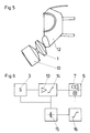
- ein Ausführungsbeispiel des Filtergerätes, wobei die Warneinrichtung zwischen einem Gasfilter und der Vollmaske geschaltet ist, und
- Fig. 6
- ein Blockschaltbild der Warneinrichtung
Wie aus den
Es gibt bereits elektrochemische Meßzellen zum Nachweis von Kohlenmonoxid, Chlor, Schwefelwasserstoff, Blausäure und Sauerstoff, die in die
- Fig. 1
- a side view of the housing receiving the warning device partially cut
- Fig. 2
- a plan view of the housing with warning device with the housing cover removed,
- Fig. 3
- an embodiment of a filter device, the warning device being connected directly to the full face mask and connected to a filter sleeve via a breathing tube,
- Fig. 4
- An embodiment of a filter device, the warning device being connected directly to the filter sleeve and connected to the full face mask via the breathing tube.
- Fig. 5
- an embodiment of the filter device, wherein the warning device is connected between a gas filter and the full mask, and
- Fig. 6
- a block diagram of the warning device
As can be seen from Figures 1 and 2, the
There are already electrochemical measuring cells for the detection of carbon monoxide, chlorine, hydrogen sulfide, hydrocyanic acid and oxygen, which can be used in the
Aus den Figuren 3 bis 5 ist ersichtlich, wie die Warneinrichtung 1 in einem Filtergerät eingebaut werden kann.
So ist in Fig. 3 das patronenartige Gehäuse 2 der Warneinrichtung 1 einerseits mit dem Anschlußstutzen 2a an dem zum Gasfilter 10 führenden Atemschlauch 11 angeschlossen und andererseits mit dem Anschlußstutzen 2b direkt an die Vollmaske 12. Das Gasfilter 10 kann z. B. auch eine Filterbüchse sein. Die Funktionsweise der derart in ein Filtergerät eingebauten Warneinrichtung, und zwar bei einem z. B. Kohlenmonoxid zurückhaltenden Gasfilter, ist folgende:
Das Gasfilter 10 wird in einer Richtung beatmet, d. h. die Einatemluft I strömt durch das Gasfilter und durch die Warneinrichtung 1 in die Vollmaske 12 des Benutzers. Die Ausatemluft II passiert dann die Warneinrichtung 1 bis hinter den Wärmeaustauscher 8 und strömt über das Ausatemventil 9 ab. Hieraus wird deutlich, daß die Warneinrichtung 1 in Pendelatmung beatmet wird. Der Wärmeaustauscher 8 wird durch die Ausatemluft II gekühlt, so daß beim erneuten Einatmen die heiße Einatemluft I aus dem Gasfilter 10 abgekühlt wird, und zwar vorteilhaft auf beispielsweise unter 40 C, um eine einwandfreie Funktion der elektrochemischen Meßzelle 3 zu gewährleisten, wenn die Einatemluft über einen in der Zeichnung nicht dargestellten Bypaß durch Diffusion durch eine Teflonmembran in das Innere der Meßzelle 3 gelangt.
Die Meßzelle arbeitet nach dem Prinzip der elektrochemischen Oxidation und dient als Meßelement zum Nachweis schädlicher Schadgaskonzentrationen in der Einatemluft, die von dem vorgeschalteten Gasfilter 10 im Falle des Erschöpfungszustandes nicht mehr zurückgehalten bzw. entfernt werden können. Mit anderen Worten: die Meßzelle 3 mißt eine bestimmte schädliche Schadstoffkonzentration, die anzeigt, daß der im Gasfilter zurückgehaltene Schadstoff durchbricht, was bedeutet, daß das Gasfilter 10 erschöpft ist.From Figures 3 to 5 it can be seen how the
Thus, in Fig. 3, the cartridge-
The
The measuring cell works on the principle of electrochemical oxidation and serves as a measuring element for the detection of harmful concentrations of harmful gas in the inhaled air, which can no longer be retained or removed by the
In Fig. 4 ist die Warneinrichtung 1 mit dem Anschlußstutzen 2a direkt an den als Filterbüchse ausgebildeten Gasfilter 10 und mit dem Anschlußstutzen 2b an den Atemschlauch 11 mit der Vollmaske 12 angeschlossen.In Fig. 4, the
In Fig. 5 ist die Warneinrichtung 1 zwischen dem Gasfilter 10 und der Vollmaske 12 geschaltet.5, the
Fig. 6 zeigt die elektronische Schaltungsanordnung der Warneinrichtung 1 als Blockschaltbild, bestehend aus der elektrochemischen Meßzelle 3 der ein Signalverstärker 13 und diesem ein Schwellwertschalter 14 sowie die Leuchtdiode 6 und der akustische Signalgeber 7 nachgeschaltet ist. Zur Energieversorgung der Schaltungsanordnung ist eine Batterie 15 mit einer Batterieüberwachung 16 vorgesehen, die den Verbrauch der Batterie an der Leuchtdiode 6 und dem Signalgeber 7 optisch und akustisch anzeigt.
Die Schaltschwelle des Schwellwertschalters 14 ist auf das den alarmauslösenden Meßwert entsprechende Meßsignal eingestellt, das einer bestimmten Schadgas-Konzentration entspricht, die das Ende der Gebrauchszeit des Gasfilters 10 anzeigt. Überschreitet beispielsweise das von der Meßzelle 3 kommende Meßsignal die eingestellte Schaltschwelle (Alarmschwelle) des Schwellwertschalters 16, so wird dessen Ausgang leitend und die Leuchtdiode 6 sowie der Signalgeber 7 werden aktiviert und lösen den optischen und akustischen Alarm aus. Das Gasfilter 10 ist dann verbraucht.Fig. 6 shows the electronic circuit arrangement of the
The switching threshold of the
Claims (6)
- Electric alarm device with optical and acoustic alarm transmitters to indicate the degree of depletion of a gas filter which removes or retains toxic gases from the air or converts them into less toxic substances in conjunction with a breathing attachment, characterised in thata) the electric alarm device (1) connected to the breathing attachment (12) is designed as a unit that is completely separate from the gas filter (10) and is fitted downstream of the gas filter in the direction of flow, andb) the alarm device (1) consists of a cartridge-type housing (2) with a connecting piece (2a and 2b) on either side in which an electrochemical measuring cell (3), which operates as a measuring element to detect hazardous concentrations of toxic gas, is arranged together with electronic circuitry (5) and the optical and acoustic alarms (6 and 7) as well as a heat exchanger (8) which divides the housing (2) into two chambers (A and B); whereby chamber A has an outlet valve (9) and the optical and acoustic alarms are a LED (6) and a signal transmitter (7) respectively.
- Alarm device according to Claim 1, characterised in that the electronic circuitry (5) for the electrochemical measuring cell (3), the signal transmitter (7) and the LED (6) are located behind the heat exchanger (8) in the other chamber (B) of the housing (2).
- Alarm device according to Claim 2, characterised in that a battery (15) is provided to supply energy to the circuitry (5), with a battery monitor (16) which indicates the depletion of the battery (15) at the LED (6) and the signal transmitter (7).
- Alarm device according to Claims 1 or 2, characterised in that the alarm device located between the breathing attachment (12) and the gas filter (10) can be ventilated in pendular fashion, whereby the exhaled air (II) flows through the heat exchanger (8) and the outlet valve (9).
- Alarm device according to Claim 1 or 2, characterised in that when it flows through the alarm device (1), the inhaled air (I) reaches the interior of the measuring cell (3) by diffusion via a bypass.
- Alarm device according to Claims 1 and 2, characterised in that the electronic circuitry (5) of the alarm device (1) has a threshold switch (14), the switching threshold of which can be set to a measuring signal which corresponds to the measured value that activates the alarm; this signal corresponds to a particular toxic gas concentration measured by the measuring cell (3), which concentration indicates the end of the service life of the gas filter (10).
Applications Claiming Priority (2)
| Application Number | Priority Date | Filing Date | Title |
|---|---|---|---|
| DE3613512A DE3613512C3 (en) | 1986-04-22 | 1986-04-22 | Electrical warning device for displaying the state of exhaustion of a gas filter which retains harmful gases |
| DE3613512 | 1986-04-22 |
Publications (3)
| Publication Number | Publication Date |
|---|---|
| EP0246444A2 EP0246444A2 (en) | 1987-11-25 |
| EP0246444A3 EP0246444A3 (en) | 1990-08-22 |
| EP0246444B1 true EP0246444B1 (en) | 1993-02-03 |
Family
ID=6299213
Family Applications (1)
| Application Number | Title | Priority Date | Filing Date |
|---|---|---|---|
| EP87105362A Expired - Lifetime EP0246444B1 (en) | 1986-04-22 | 1987-04-10 | Warning device for indicating the state of exhaustion of a gas filter |
Country Status (3)
| Country | Link |
|---|---|
| US (1) | US4873970A (en) |
| EP (1) | EP0246444B1 (en) |
| DE (2) | DE3613512C3 (en) |
Families Citing this family (51)
| Publication number | Priority date | Publication date | Assignee | Title |
|---|---|---|---|---|
| DE3818052A1 (en) * | 1988-05-27 | 1989-12-07 | Geraetebau Gmbh | RESPIRATORY MASK |
| DE3838531A1 (en) * | 1988-11-14 | 1990-05-17 | Wolfgang Gerigk | Device for the detection of infected and poisoned breathing air |
| DE4009107A1 (en) * | 1990-03-21 | 1991-09-26 | Auergesellschaft Gmbh | WARNING DEVICE WITH A MEASURING CELL AND ALARMS TO INDICATE THE DEFAULT OF A GAS FILTER |
| CA2020503C (en) * | 1990-07-05 | 1998-11-17 | Jacques Lesage | Chemical cartridge for protective respiratory mask |
| FR2677765B1 (en) * | 1991-06-17 | 1994-06-17 | Commissariat Energie Atomique | PROCESS FOR MONITORING THE SATURATION STATE OF A FILTERED ACTIVE CARBON MASS OF A FILTRATION DEVICE AND RESPIRATORY MASK CARTRIDGE USING THE SAME. |
| DE4132680C2 (en) * | 1991-10-01 | 1994-02-10 | Draegerwerk Ag | Respirator mask with inner half mask and pollutant indicator |
| DE4133235A1 (en) * | 1991-10-07 | 1993-04-08 | Draegerwerk Ag | FAN-SUPPORTED BREATHING DEVICE WITH AN ADD-ON CONTROL UNIT |
| US5117821A (en) * | 1991-10-18 | 1992-06-02 | White George M | Hunting mask with breath odor control system |
| DE4214239C2 (en) * | 1992-04-30 | 1994-06-16 | Draegerwerk Ag | RESPIRATORY MASK WITH AN INDICATOR |
| US5338430A (en) * | 1992-12-23 | 1994-08-16 | Minnesota Mining And Manufacturing Company | Nanostructured electrode membranes |
| EP0722352B1 (en) * | 1993-10-01 | 2000-05-03 | Minnesota Mining And Manufacturing Company | Speech transmission adaptor for use with a respirator mask |
| US5906203A (en) * | 1994-08-01 | 1999-05-25 | Safety Equipment Sweden Ab | Breathing apparatus |
| TW287952B (en) * | 1994-08-31 | 1996-10-11 | Lifepro Inc | |
| US5666949A (en) * | 1994-10-24 | 1997-09-16 | Minnesota Mining And Manufacturing Company | Exposure indicator with continuous alarm signal indicating multiple conditions |
| US5659296A (en) * | 1994-10-24 | 1997-08-19 | Minnesota Mining And Manufacturing Company | Exposure indicating apparatus |
| US5856198A (en) * | 1994-12-28 | 1999-01-05 | Extraction Systems, Inc. | Performance monitoring of gas-phase air filters |
| US5676133A (en) * | 1995-06-14 | 1997-10-14 | Apotheus Laboratories, Inc. | Expiratory scavenging method and apparatus and oxygen control system for post anesthesia care patients |
| US5878743A (en) * | 1996-09-23 | 1999-03-09 | Respironics, Inc. | Pressure sensitive flow control valve |
| US6003511A (en) * | 1996-11-18 | 1999-12-21 | Medlis Corp. | Respiratory circuit terminal for a unilimb respiratory device |
| DE19650897A1 (en) * | 1996-12-07 | 1998-06-10 | T E M Tech Entwicklung Und Man | Apparatus and method for increasing the safety of respiratory masks |
| WO1998038508A1 (en) * | 1997-02-28 | 1998-09-03 | Extraction Systems, Inc. | System for detecting amine and other basic molecular contamination in a gas |
| US6096267A (en) | 1997-02-28 | 2000-08-01 | Extraction Systems, Inc. | System for detecting base contaminants in air |
| US6186140B1 (en) * | 1997-03-14 | 2001-02-13 | 3M Innovative Properties Company | Respiratory filter element having a storage device for keeping track of filter usage and a system for use therewith |
| US5937852A (en) * | 1997-04-08 | 1999-08-17 | The Board Of Regents Of The University Of Texas System | Apparatus for induction of inhaled pharmacological agent by a pediatric patient |
| US6207460B1 (en) | 1999-01-14 | 2001-03-27 | Extraction Systems, Inc. | Detection of base contaminants in gas samples |
| KR20020001780A (en) | 1999-03-17 | 2002-01-09 | 추후제출 | Sensor device and method of detecting gases or fumes in air |
| DE19911867C2 (en) * | 1999-03-17 | 2002-02-21 | T E M Techn Entwicklungen Und | Sensor system for the detection of gases and vapors in air |
| US6761169B2 (en) * | 2000-08-17 | 2004-07-13 | Vase Technology | Bi/multi-directional filter cartridge and filter platform for mounting the cartridge thereon |
| US20060048777A1 (en) * | 2003-03-21 | 2006-03-09 | Interspiro, Inc. | Apparatus and method for providing breathable air and bodily protection in a contaminated environment |
| US20040182394A1 (en) * | 2003-03-21 | 2004-09-23 | Alvey Jeffrey Arthur | Powered air purifying respirator system and self contained breathing apparatus |
| US7647927B2 (en) * | 2003-08-22 | 2010-01-19 | Wilcox Industries Corp. | Self-contained breathing system |
| US7100423B2 (en) * | 2003-09-04 | 2006-09-05 | Midwest Research Institute | Method and apparatus for monitoring particles in a flowing gas |
| US20100139661A1 (en) * | 2003-12-18 | 2010-06-10 | Scott Technologies, Inc. | Air breathing hose with integrated electrical wiring |
| US20070105494A1 (en) * | 2005-11-08 | 2007-05-10 | Esco Micro Pte Ltd | Ductless fume hood with improved filter monitoring system and extended filter life |
| US8336543B2 (en) * | 2009-05-22 | 2012-12-25 | 3M Innovative Properties Company | Filter cartridge having cover for masking service life indicator |
| US8225782B2 (en) * | 2009-05-22 | 2012-07-24 | 3M Innovative Properties Company | Filter cartridge having location-registered view window for end-of-service-life-indicator (ESLI) |
| US8365723B2 (en) * | 2009-05-22 | 2013-02-05 | 3M Innovative Properties Company | Filter cartridge having cone of visibility for end-of-service-life-indicator (ESLI) |
| US8372186B2 (en) | 2009-08-14 | 2013-02-12 | Gregory J. Dobbyn | Ductless fume hood gas monitoring and detection system |
| EP2539023B1 (en) * | 2010-02-26 | 2018-08-15 | Zodiac Aerotechnics | Method and device for determining partial pressure of a gaseous constituent and regulator of breathing mask for aircraft occupant |
| US9616192B2 (en) | 2010-03-25 | 2017-04-11 | Resmed Paris Sas | Breathable gas inlet control device for respiratory treatment apparatus |
| WO2011123403A1 (en) | 2010-04-02 | 2011-10-06 | 3M Innovative Properties Company | Filter systems including optical analyte sensors and optical readers |
| CA2806457A1 (en) | 2010-08-06 | 2012-02-09 | Scott Technologies, Inc. | Method and apparatus for integrating chemical and environmental sensors into an air purification filter through a reusable sensor post |
| US8616205B2 (en) | 2010-10-06 | 2013-12-31 | Honeywell International Inc. | Respirator with end-of-service-life detection |
| US9011584B2 (en) * | 2011-08-25 | 2015-04-21 | Honeywell International Inc. | End of service life indicator for respirator |
| US9079049B2 (en) | 2011-11-02 | 2015-07-14 | Honeywell International Inc. | Respirators with a sacrificial cartridge for end of service life indication |
| IN2014CN04300A (en) | 2011-12-12 | 2015-09-04 | 3M Innovative Properties Co | |
| US9283411B2 (en) | 2013-04-19 | 2016-03-15 | Honeywell International Inc. | Gas sensing drift compensation using gas self-referencing for end of service life indication for respirators |
| EP2875847B1 (en) * | 2013-11-26 | 2020-03-11 | Naphtachimie S.A. | Secure device for respiratory protection |
| CN107072338A (en) | 2014-09-05 | 2017-08-18 | 霍尼韦尔国际公司 | The end-of-life indicator of disposable face guard |
| ITUB201594612U1 (en) * | 2015-11-17 | 2017-05-17 | Spasciani S P A | PERSONAL PROTECTIVE EQUIPMENT FOR RESPIRATORY TRACKS PROVIDED WITH ALARM SYSTEM. |
| GB2579210A (en) * | 2018-11-23 | 2020-06-17 | World Wide Welding Ltd | Powered air personal respirator |
Family Cites Families (10)
| Publication number | Priority date | Publication date | Assignee | Title |
|---|---|---|---|---|
| US1320935A (en) * | 1919-11-04 | schwartz | ||
| GB170404A (en) * | 1920-07-20 | 1921-10-20 | Leonard Angelo Levy | A carbon monoxide respirator |
| US1474205A (en) * | 1921-10-11 | 1923-11-13 | Mine Safety Appliances Co | Gas mask |
| AT155693B (en) * | 1934-09-21 | 1939-03-10 | Pirelli | Device for displaying the exhaustion status of gas filters and protection devices. |
| FR843542A (en) * | 1937-09-29 | 1939-07-05 | Pirelli | Device for signaling exhaustion of gas filters |
| DE1721541U (en) * | 1954-05-22 | 1956-05-03 | Draegerwerk Ag | DEVICE FOR INDICATING THE EXHAUST OF A BREATHING FILTER. |
| DE1120774B (en) * | 1960-04-26 | 1961-12-28 | Mine Safety Appliances Co | Detector cell for measuring the concentration of a gas component |
| US3902485A (en) * | 1974-02-08 | 1975-09-02 | Richard A Wallace | Chemically activated warning system |
| DE2529058A1 (en) * | 1975-06-30 | 1977-02-03 | Richard A Wallace | Electric heat-sensitive alarm for detecting toxic gases - is for use in chemical installations and mines and with breathing apparatus |
| US4051006A (en) * | 1976-03-22 | 1977-09-27 | Beckman Instruments, Inc. | Portable electrochemical cell structure |
-
1986
- 1986-04-22 DE DE3613512A patent/DE3613512C3/en not_active Expired - Fee Related
-
1987
- 1987-04-10 EP EP87105362A patent/EP0246444B1/en not_active Expired - Lifetime
- 1987-04-10 DE DE8787105362T patent/DE3783944D1/en not_active Expired - Fee Related
-
1989
- 1989-03-10 US US07/323,069 patent/US4873970A/en not_active Expired - Lifetime
Also Published As
| Publication number | Publication date |
|---|---|
| EP0246444A3 (en) | 1990-08-22 |
| DE3613512A1 (en) | 1987-10-29 |
| DE3613512C2 (en) | 1994-09-29 |
| DE3613512C3 (en) | 1994-09-29 |
| US4873970A (en) | 1989-10-17 |
| EP0246444A2 (en) | 1987-11-25 |
| DE3783944D1 (en) | 1993-03-18 |
Similar Documents
| Publication | Publication Date | Title |
|---|---|---|
| EP0246444B1 (en) | Warning device for indicating the state of exhaustion of a gas filter | |
| EP0343521B1 (en) | Breath protection mask | |
| KR100733641B1 (en) | Apparatus and method for breathing apparatus component coupling | |
| DE2934241C2 (en) | Warning device for use in anesthesia machines | |
| DE3742639C2 (en) | Closed circuit breathing apparatus | |
| US3773044A (en) | Chemical breathing apparatus with alarm device | |
| DE2136968B2 (en) | Fire alarm systems | |
| DE3109658A1 (en) | ELECTRICALLY CONTROLLABLE RESPIRATORY DEVICE ACCORDING TO THE CIRCUIT PRINCIPLE | |
| EP0447619B1 (en) | Warning system with a measuring cell and alarm signal to indicate the condition of a gas filter | |
| EP1165186B1 (en) | Method and sensor device for detecting gases or fumes in air | |
| DE2147718C3 (en) | Carbon dioxide warning device | |
| DE19911869B4 (en) | Novel respirator mask with sensor microsystem and method for operating the same | |
| CN110160855B (en) | Gas dilution sampling joint and use method | |
| DE202013007337U1 (en) | Test case with microprocessor-controlled measuring device for filter saturation and breathing air gas quality | |
| DE102015007798A1 (en) | Sensor, gas cleaning unit and fuel cell system | |
| CN211024876U (en) | Hydrogen sulfide gas mask | |
| CN216669918U (en) | Toxic gas monitoring facilities | |
| CN214704907U (en) | Toxic gas alarm instrument | |
| CN210269763U (en) | Ventilation monitoring integrated device for limited space | |
| Damez et al. | Safety problems in ozonation plants | |
| CN216908947U (en) | Expiratory valve and mask with same | |
| DE1163153B (en) | Warning device for pressurized gas breathing apparatus | |
| DE2924048A1 (en) | Electric conductivity monitor for highly purified water - has electronic switch connecting display and/or actuator to source only, when electrodes are dipped in water | |
| DE2425647C3 (en) | Sensor for CO2 measuring device | |
| WO2011104327A1 (en) | Diving rebreather comprising a mouthpiece |
Legal Events
| Date | Code | Title | Description |
|---|---|---|---|
| PUAI | Public reference made under article 153(3) epc to a published international application that has entered the european phase |
Free format text: ORIGINAL CODE: 0009012 |
|
| 17P | Request for examination filed |
Effective date: 19870421 |
|
| AK | Designated contracting states |
Kind code of ref document: A2 Designated state(s): BE DE FR GB IT NL SE |
|
| PUAL | Search report despatched |
Free format text: ORIGINAL CODE: 0009013 |
|
| AK | Designated contracting states |
Kind code of ref document: A3 Designated state(s): BE DE FR GB IT NL SE |
|
| 17Q | First examination report despatched |
Effective date: 19911114 |
|
| ITTA | It: last paid annual fee | ||
| GRAA | (expected) grant |
Free format text: ORIGINAL CODE: 0009210 |
|
| AK | Designated contracting states |
Kind code of ref document: B1 Designated state(s): BE DE FR GB IT NL SE |
|
| ITF | It: translation for a ep patent filed |
Owner name: JACOBACCI CASETTA & PERANI S.P.A. |
|
| REF | Corresponds to: |
Ref document number: 3783944 Country of ref document: DE Date of ref document: 19930318 |
|
| GBT | Gb: translation of ep patent filed (gb section 77(6)(a)/1977) |
Effective date: 19930218 |
|
| ET | Fr: translation filed | ||
| PLBI | Opposition filed |
Free format text: ORIGINAL CODE: 0009260 |
|
| 26 | Opposition filed |
Opponent name: DRAEGERWERK AG Effective date: 19930922 |
|
| NLR1 | Nl: opposition has been filed with the epo |
Opponent name: DRAEGERWERK AG |
|
| EAL | Se: european patent in force in sweden |
Ref document number: 87105362.5 |
|
| PLBN | Opposition rejected |
Free format text: ORIGINAL CODE: 0009273 |
|
| STAA | Information on the status of an ep patent application or granted ep patent |
Free format text: STATUS: OPPOSITION REJECTED |
|
| 27O | Opposition rejected |
Effective date: 19950429 |
|
| NLR2 | Nl: decision of opposition | ||
| PGFP | Annual fee paid to national office [announced via postgrant information from national office to epo] |
Ref country code: SE Payment date: 19990315 Year of fee payment: 13 |
|
| PGFP | Annual fee paid to national office [announced via postgrant information from national office to epo] |
Ref country code: GB Payment date: 19990323 Year of fee payment: 13 |
|
| PGFP | Annual fee paid to national office [announced via postgrant information from national office to epo] |
Ref country code: BE Payment date: 19990414 Year of fee payment: 13 |
|
| PGFP | Annual fee paid to national office [announced via postgrant information from national office to epo] |
Ref country code: FR Payment date: 19990415 Year of fee payment: 13 |
|
| PGFP | Annual fee paid to national office [announced via postgrant information from national office to epo] |
Ref country code: NL Payment date: 19990429 Year of fee payment: 13 |
|
| PG25 | Lapsed in a contracting state [announced via postgrant information from national office to epo] |
Ref country code: GB Free format text: LAPSE BECAUSE OF NON-PAYMENT OF DUE FEES Effective date: 20000410 |
|
| PG25 | Lapsed in a contracting state [announced via postgrant information from national office to epo] |
Ref country code: SE Free format text: LAPSE BECAUSE OF NON-PAYMENT OF DUE FEES Effective date: 20000411 |
|
| PG25 | Lapsed in a contracting state [announced via postgrant information from national office to epo] |
Ref country code: BE Free format text: LAPSE BECAUSE OF NON-PAYMENT OF DUE FEES Effective date: 20000430 |
|
| BERE | Be: lapsed |
Owner name: AUERGESELLSCHAFT G.M.B.H. Effective date: 20000430 |
|
| PG25 | Lapsed in a contracting state [announced via postgrant information from national office to epo] |
Ref country code: NL Free format text: LAPSE BECAUSE OF NON-PAYMENT OF DUE FEES Effective date: 20001101 |
|
| GBPC | Gb: european patent ceased through non-payment of renewal fee |
Effective date: 20000410 |
|
| EUG | Se: european patent has lapsed |
Ref document number: 87105362.5 |
|
| PG25 | Lapsed in a contracting state [announced via postgrant information from national office to epo] |
Ref country code: FR Free format text: LAPSE BECAUSE OF NON-PAYMENT OF DUE FEES Effective date: 20001229 |
|
| NLV4 | Nl: lapsed or anulled due to non-payment of the annual fee |
Effective date: 20001101 |
|
| REG | Reference to a national code |
Ref country code: FR Ref legal event code: ST |
|
| PGFP | Annual fee paid to national office [announced via postgrant information from national office to epo] |
Ref country code: DE Payment date: 20020117 Year of fee payment: 16 |
|
| PG25 | Lapsed in a contracting state [announced via postgrant information from national office to epo] |
Ref country code: DE Free format text: LAPSE BECAUSE OF NON-PAYMENT OF DUE FEES Effective date: 20031101 |
|
| PG25 | Lapsed in a contracting state [announced via postgrant information from national office to epo] |
Ref country code: IT Free format text: LAPSE BECAUSE OF NON-PAYMENT OF DUE FEES Effective date: 20050410 |