EP0244875B1 - Procédé et dispositif pour commander un moteur alimenté en gaz liquéfié (GPL) - Google Patents
Procédé et dispositif pour commander un moteur alimenté en gaz liquéfié (GPL) Download PDFInfo
- Publication number
- EP0244875B1 EP0244875B1 EP87106739A EP87106739A EP0244875B1 EP 0244875 B1 EP0244875 B1 EP 0244875B1 EP 87106739 A EP87106739 A EP 87106739A EP 87106739 A EP87106739 A EP 87106739A EP 0244875 B1 EP0244875 B1 EP 0244875B1
- Authority
- EP
- European Patent Office
- Prior art keywords
- gas
- internal combustion
- compensation valve
- piston
- liquefied
- Prior art date
- Legal status (The legal status is an assumption and is not a legal conclusion. Google has not performed a legal analysis and makes no representation as to the accuracy of the status listed.)
- Expired - Lifetime
Links
- 238000000034 method Methods 0.000 title description 2
- 239000007789 gas Substances 0.000 claims abstract description 115
- 238000002485 combustion reaction Methods 0.000 claims abstract description 42
- 239000000203 mixture Substances 0.000 claims abstract description 29
- ATUOYWHBWRKTHZ-UHFFFAOYSA-N Propane Chemical compound CCC ATUOYWHBWRKTHZ-UHFFFAOYSA-N 0.000 claims abstract description 26
- 239000001273 butane Substances 0.000 claims abstract description 16
- IJDNQMDRQITEOD-UHFFFAOYSA-N n-butane Chemical compound CCCC IJDNQMDRQITEOD-UHFFFAOYSA-N 0.000 claims abstract description 16
- OFBQJSOFQDEBGM-UHFFFAOYSA-N n-pentane Natural products CCCCC OFBQJSOFQDEBGM-UHFFFAOYSA-N 0.000 claims abstract description 16
- 239000001294 propane Substances 0.000 claims abstract description 13
- 239000000470 constituent Substances 0.000 claims abstract 2
- 239000003915 liquefied petroleum gas Substances 0.000 claims description 13
- 239000000446 fuel Substances 0.000 claims description 10
- 238000012546 transfer Methods 0.000 claims description 3
- 238000002156 mixing Methods 0.000 abstract description 3
- 239000007788 liquid Substances 0.000 description 43
- 230000001105 regulatory effect Effects 0.000 description 5
- 230000005540 biological transmission Effects 0.000 description 4
- 238000010586 diagram Methods 0.000 description 4
- TVMXDCGIABBOFY-UHFFFAOYSA-N octane Chemical compound CCCCCCCC TVMXDCGIABBOFY-UHFFFAOYSA-N 0.000 description 3
- 230000006835 compression Effects 0.000 description 2
- 238000007906 compression Methods 0.000 description 2
- 238000001816 cooling Methods 0.000 description 2
- 238000012937 correction Methods 0.000 description 2
- 230000000694 effects Effects 0.000 description 2
- 239000003344 environmental pollutant Substances 0.000 description 2
- 231100000719 pollutant Toxicity 0.000 description 2
- 230000006978 adaptation Effects 0.000 description 1
- 230000009286 beneficial effect Effects 0.000 description 1
- 230000001419 dependent effect Effects 0.000 description 1
- 238000011161 development Methods 0.000 description 1
- 230000009365 direct transmission Effects 0.000 description 1
- 238000006073 displacement reaction Methods 0.000 description 1
- 230000009977 dual effect Effects 0.000 description 1
- 238000010438 heat treatment Methods 0.000 description 1
- 238000009434 installation Methods 0.000 description 1
- 239000007791 liquid phase Substances 0.000 description 1
- 238000012423 maintenance Methods 0.000 description 1
- 238000005259 measurement Methods 0.000 description 1
- 239000012071 phase Substances 0.000 description 1
- 238000002360 preparation method Methods 0.000 description 1
- 238000011160 research Methods 0.000 description 1
- 238000007789 sealing Methods 0.000 description 1
Images

Classifications
-
- F—MECHANICAL ENGINEERING; LIGHTING; HEATING; WEAPONS; BLASTING
- F02—COMBUSTION ENGINES; HOT-GAS OR COMBUSTION-PRODUCT ENGINE PLANTS
- F02D—CONTROLLING COMBUSTION ENGINES
- F02D19/00—Controlling engines characterised by their use of non-liquid fuels, pluralities of fuels, or non-fuel substances added to the combustible mixtures
- F02D19/02—Controlling engines characterised by their use of non-liquid fuels, pluralities of fuels, or non-fuel substances added to the combustible mixtures peculiar to engines working with gaseous fuels
- F02D19/026—Measuring or estimating parameters related to the fuel supply system
- F02D19/027—Determining the fuel pressure, temperature or volume flow, the fuel tank fill level or a valve position
-
- F—MECHANICAL ENGINEERING; LIGHTING; HEATING; WEAPONS; BLASTING
- F02—COMBUSTION ENGINES; HOT-GAS OR COMBUSTION-PRODUCT ENGINE PLANTS
- F02D—CONTROLLING COMBUSTION ENGINES
- F02D19/00—Controlling engines characterised by their use of non-liquid fuels, pluralities of fuels, or non-fuel substances added to the combustible mixtures
- F02D19/02—Controlling engines characterised by their use of non-liquid fuels, pluralities of fuels, or non-fuel substances added to the combustible mixtures peculiar to engines working with gaseous fuels
- F02D19/021—Control of components of the fuel supply system
- F02D19/023—Control of components of the fuel supply system to adjust the fuel mass or volume flow
-
- F—MECHANICAL ENGINEERING; LIGHTING; HEATING; WEAPONS; BLASTING
- F02—COMBUSTION ENGINES; HOT-GAS OR COMBUSTION-PRODUCT ENGINE PLANTS
- F02D—CONTROLLING COMBUSTION ENGINES
- F02D19/00—Controlling engines characterised by their use of non-liquid fuels, pluralities of fuels, or non-fuel substances added to the combustible mixtures
- F02D19/02—Controlling engines characterised by their use of non-liquid fuels, pluralities of fuels, or non-fuel substances added to the combustible mixtures peculiar to engines working with gaseous fuels
- F02D19/026—Measuring or estimating parameters related to the fuel supply system
- F02D19/029—Determining density, viscosity, concentration or composition
-
- F—MECHANICAL ENGINEERING; LIGHTING; HEATING; WEAPONS; BLASTING
- F02—COMBUSTION ENGINES; HOT-GAS OR COMBUSTION-PRODUCT ENGINE PLANTS
- F02M—SUPPLYING COMBUSTION ENGINES IN GENERAL WITH COMBUSTIBLE MIXTURES OR CONSTITUENTS THEREOF
- F02M21/00—Apparatus for supplying engines with non-liquid fuels, e.g. gaseous fuels stored in liquid form
- F02M21/02—Apparatus for supplying engines with non-liquid fuels, e.g. gaseous fuels stored in liquid form for gaseous fuels
- F02M21/0203—Apparatus for supplying engines with non-liquid fuels, e.g. gaseous fuels stored in liquid form for gaseous fuels characterised by the type of gaseous fuel
- F02M21/0209—Hydrocarbon fuels, e.g. methane or acetylene
- F02M21/0212—Hydrocarbon fuels, e.g. methane or acetylene comprising at least 3 C-Atoms, e.g. liquefied petroleum gas [LPG], propane or butane
-
- F—MECHANICAL ENGINEERING; LIGHTING; HEATING; WEAPONS; BLASTING
- F02—COMBUSTION ENGINES; HOT-GAS OR COMBUSTION-PRODUCT ENGINE PLANTS
- F02M—SUPPLYING COMBUSTION ENGINES IN GENERAL WITH COMBUSTIBLE MIXTURES OR CONSTITUENTS THEREOF
- F02M21/00—Apparatus for supplying engines with non-liquid fuels, e.g. gaseous fuels stored in liquid form
- F02M21/02—Apparatus for supplying engines with non-liquid fuels, e.g. gaseous fuels stored in liquid form for gaseous fuels
- F02M21/0218—Details on the gaseous fuel supply system, e.g. tanks, valves, pipes, pumps, rails, injectors or mixers
- F02M21/023—Valves; Pressure or flow regulators in the fuel supply or return system
- F02M21/0239—Pressure or flow regulators therefor
-
- F—MECHANICAL ENGINEERING; LIGHTING; HEATING; WEAPONS; BLASTING
- F02—COMBUSTION ENGINES; HOT-GAS OR COMBUSTION-PRODUCT ENGINE PLANTS
- F02M—SUPPLYING COMBUSTION ENGINES IN GENERAL WITH COMBUSTIBLE MIXTURES OR CONSTITUENTS THEREOF
- F02M21/00—Apparatus for supplying engines with non-liquid fuels, e.g. gaseous fuels stored in liquid form
- F02M21/02—Apparatus for supplying engines with non-liquid fuels, e.g. gaseous fuels stored in liquid form for gaseous fuels
- F02M21/06—Apparatus for de-liquefying, e.g. by heating
-
- Y—GENERAL TAGGING OF NEW TECHNOLOGICAL DEVELOPMENTS; GENERAL TAGGING OF CROSS-SECTIONAL TECHNOLOGIES SPANNING OVER SEVERAL SECTIONS OF THE IPC; TECHNICAL SUBJECTS COVERED BY FORMER USPC CROSS-REFERENCE ART COLLECTIONS [XRACs] AND DIGESTS
- Y02—TECHNOLOGIES OR APPLICATIONS FOR MITIGATION OR ADAPTATION AGAINST CLIMATE CHANGE
- Y02T—CLIMATE CHANGE MITIGATION TECHNOLOGIES RELATED TO TRANSPORTATION
- Y02T10/00—Road transport of goods or passengers
- Y02T10/10—Internal combustion engine [ICE] based vehicles
- Y02T10/30—Use of alternative fuels, e.g. biofuels
Definitions
- a method and a device for power control are presented for internal combustion engines operated with liquefied petroleum gas, main components propane / butane (LPG), in particular Otto gas engines, the liquefied gas being brought into the gaseous state in an evaporator and then mixed with air in the gas mixer is before it gets into the engine.
- LPG propane / butane
- Otto gas engines are known, whose combustion mixture, air-gas mixture, is sucked in by the internal combustion engine directly from the gas mixer. In this case, no influence is exerted on the composition of the liquid gas and thus the calorific value, and therefore not on the power setting of the internal combustion engine. As a result, the output changes in proportion to the calorific value of the propane / butane mixture. Since there is no German or European standard for liquefied petroleum gas as a fuel, the composition of liquefied gases is often different from country to country and season.
- the main components propane and butane can vary in the mixing ratio from 100 to 0% to 20 to 80%. Depending on the butane content, the specific, volume-related calorific value increases up to 25%. At the same time, as the butane content increases, the octane number drops by up to 13 units RON (research octane number), which also significantly reduces the knock resistance of the fuel.
- a device for regulating the fuel supply for internal combustion engines operated with liquefied petroleum gas depending on the calorific value is known.
- the structure provides a device which is inserted between the evaporator and the carburetor and which comprises two valve devices. Each valve device is acted upon by one of the two state variables or pressure and temperature of the gaseous fuel. Together, the device effects the fuel metering for the internal combustion engine.
- This known device shows a complex structure with a large number of necessary settings combined with a high maintenance effort.
- the object on which the invention is based is to present a compactly constructed device comprising few components, which effectively ensures permanent engine operation with a further requirement not to deteriorate the pollutant emissions in the entire operating range of the internal combustion engine, and simple adjustment of high availability of the internal combustion engine make sure.
- the internal combustion engine can thus be operated optimally regardless of the composition of the liquid gas, that is to say with changing propane / butane proportions.
- This goal is achieved by transferring the as-state values, the liquid gas pressure and the liquid gas temperatures, to a metering device. The necessary corrections are made according to the specific vapor pressure curves of the liquid gas. The mixture proportions can be determined with the help of the vapor pressure curves, since every propane / butane mixture moves on this state line. The measurement of pressure and temperature leads to the identification of the liquid gas mixture.
- a further advantage which arises as a result of the gas quantity control according to the invention as a function of the gas mixture components and thus the calorific value is the exhaust gas quality, which does not deteriorate significantly even with increasing butane proportions and the associated higher air requirement, in particular in the part-load range. With such changed conditions, the metering device controls the amount of gas so that this effect is almost avoided.
- a compensation valve is provided as the metering device according to the invention. Inserted into the connecting line between the evaporator and the air mixer, the gas quantity can be metered and regulated directly through the compensation valve.
- the compensation valve serves as a control valve or throttle element which is controlled depending on the gas composition and the associated stoichiometric air requirement and thus controls the amount of gas in the low-pressure gas line between the evaporator and the engine.
- the device also provides that the compensation valve has a specially designed variable throttle cross section.
- the cross-sectional geometry can be adjusted, for example, so that, under standard conditions (e.g. DIN 70 020, which relates to an ambient temperature and gas temperature of 20 ° C), a uniform engine rating is achieved for all the liquid gas mixtures mentioned. This possibility also offers an adaptation of the passage geometry to the composition of the liquid gas.
- a further development of this idea provides that a direct transmission of the liquid gas pressure to the piston of the compensation valve serves as a manipulated variable for changing the passage cross section.
- the gas pressure change resulting from changing mixing ratios in the liquefied petroleum gas can be used at any time to adapt to the amount of gas supplied to the internal combustion engine without great installation effort.
- the invention also provides for an influence by the liquid gas temperature, by means of which an additional adjustment of the compensation valve is achieved.
- a compensation valve is designed, designed as a rotatable piston valve, in which the passage geometry is provided with a control edge.
- the LPG pressure acts on the spring-loaded piston.
- the rotation of the piston can be achieved with the aid of transmission elements which rotate the piston when the liquid gas temperature changes.
- a passage geometry which is provided with an oblique edge is advantageous.
- an inclined control edge achieves a readily determinable metering of the gas flow that passes through.
- transducers as the transmission element for adjusting the piston in the compensation valve.
- the temperature sensor and pressure sensor in the LPG container transfer the measured values to the transducers for adjusting the piston in the compensation valve.
- the transducer adjusts, i.e. Rotation and / or displacement in the axial direction of the piston is achieved.
- the claim 1 provides that a control magnet is flanged directly to the compensation valve.
- a magnet is envisaged which acts as a function of the gas temperature and exerts a superimposing force on the piston.
- the control magnet thus acts on the force an increase in temperature, which is exerted on the piston by the liquid gas pressure.
- the control magnet thus compensates for the influence of gas temperature in gas quantity control, which is primarily dependent on the liquid gas pressure.
- a transfer to dual / FUEL internal combustion engines is also envisaged. These internal combustion engines are operated with two fuels, in particular a liquid and a gaseous fuel.
- the compensation valve which regulates and adjusts the amount of gas depending on the composition of the LPG, is also suitable for this purpose, in order to prevent fluctuations in the calorific value in the LPG and thus differences in performance.
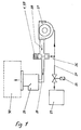
- FIG. 1 shows all components for internal combustion engines operated with liquid gas for the preparation and supply of the liquid gas as well as the new compensation valve presented by the invention.
- a solenoid valve 25 is connected directly behind the gas container 23, which can interrupt the gas supply.
- the solenoid valve 25 can also be used as a safety device, for example in the form that it can directly interrupt the gas flow in the event of excess pressure or excessive gas flow, for example due to a leak in the line system.
- the solenoid valve 25 and the evaporator 27 there is a branch in the liquid gas line 24 connected to the pressure line 26 through which the gas pressure is transmitted to the metering device 37, the compensation valve 1.
- the gas exiting the evaporator 27 and brought into the gas state passes through the gas line 28 into the compensation valve 1.
- the opening cross section in the compensation valve 1 can thus be regulated in particular by the liquid gas pressure.
- the liquid gas composition can thus influence the amount of gas that flows into the internal combustion engine.
- the internal combustion engine 30, which is shown in simplified form as a rectangle in the present diagram, sucks in the gas metered by the compensation valve 1, which is mixed with air in the gas mixer 29 and reaches the internal combustion engine 30 as a gas-air mixture for combustion there.
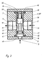
- the exemplary embodiment shows a metering device 37 which is cylindrical in the outer contour, the compensation valve 1, consisting of the housing 4 and the inner part 6 located therein.
- the outer contour of the compensation valve 1 can be rectangular or be formed in another exposed geometric shape.
- the inner part 6 has an axial bore 31 through which the gas is passed. The gas enters from the evaporator 27 in the inlet 2 and emerges from the compensation valve 1 through the outlet 3 opposite.
- the cylinder 12 is introduced in the center of the compensation valve 1 in a radial bore 32, crossing the axial bore 31.
- the cylinder 12, arranged in the inner part 6 by the seal 16 and sealing radially with the inner part 6, serves to receive the piston 7.
- the cylinder 12 has openings, the cylinder inlet and the cylinder outlet.
- the cylinder inlet 13 is attached in the direction of the inlet 2, the cylinder outlet 14 is aligned with the outlet 3.
- the cylinder inlet 13 and the cylinder outlet 14 are designed differently and are arranged in different positions relative to one another.
- the control edge 36 on the upper piston part 33 on the side facing the lower piston part 10 releases a certain part of this opening, depending on the position predetermined by the gas pressure.
- a defined gas volume flow can flow through the compensation valve 1 to the internal combustion engine 30.
- the piston 7 is acted upon by the liquid gas pressure which is present in the pressure chamber 17.
- the piston 7 has a large taper over a region that is larger than the cylinder inlet 13, which is identified as connection 9 and divides the piston into a lower part 10 and an upper part 33.
- the tapering of the piston 7 is carried out so far that the flow cross-section is equal to or greater than the cross-section of the cylinder inlet 13.
- the liquid gas pressure in the pressure chamber 17 acts against a compression spring 15 arranged opposite on the piston.
- the guide 8 is intended for the compression spring 15 and has the further task of limiting the adjustment path of the piston 7 when the guide 8 is in contact with the housing 4.
- the lower piston part 10 is sealed off from the pressure chamber 17 by the seal 11.
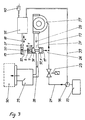
- FIG. 3 shows a largely identical structure of a liquid gas supply for an internal combustion engine as in FIG. 1.
- a further adjustment possibility of the metering device 37 is provided by the liquid gas temperature from the gas container 23.
- the liquid gas temperature is transmitted to the transducer by the temperature transmitter 38 and the electrical connection 39.
- the temperature sensor 38 can measure the temperature in the liquid gas container 23 or immediately behind it in the liquid gas line 24.
- the transducer 35 is connected to the voltage source 40.
- the rack 18 movable in the X direction causes the piston 7 to rotate, which are connected to one another via the guide 8, the shaft 22, the gear 20 and the rack 18.
- the piston 7 has an oblique control edge 34 which changes the cross section of the cylinder inlet 13 when rotated. Furthermore, the piston 7 can be displaced vertically in the direction Y from the gas pressure present in the pressure chamber 17.
- the toothing width 21 of the toothed rack 18 is also designed by the corresponding amount of a possible vertical shift to Y.
- FIG. 4 shows in section the compensation valve 1, as already explained in more detail in the description of FIG. 2, which is provided with an integrated actuating magnet 41.
- This is located almost centrally in the magnet housing 42, which is flanged on one side to the housing 4.
- the guide 8 is extended through the housing 4 and continues through the actuating magnet 41 up to the stop formed by the adjusting screw 44. Lying on the same axis with the guide 8, the adjusting screw 44 is screwed into the magnet housing 42 from the outside. With the help of the lock nut 43 the screwing depth of the adjusting screw 44 can be adjusted.
- the actuating magnet 41 is intended to compensate for the influence of gas temperature in compensation valves, the manipulated variable of which is the liquefied gas pressure.
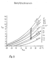
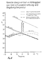
- the vapor pressure curves in FIG. 5 show the changes in calorific value as a function of the liquid gas composition with the main proportions propane and butane.
- the limit mixture ratios which can occur due to a lack of standardization and which can range from a propane / butane content of 100/0% to 20/80%, are clearly highlighted.
- An example of the temperature-pressure dependence of the liquid gas mixture is shown in the curve. With a 30/70% mixture, for example, the pressure increases from 4.1 bar at 20 ° C to 7 bar at 40 ° C.
- the volume flow in an exclusively pressure-controlled compensation valve 1 then corresponds to that of an 80/20% mixture at 20 ° C. The fuel energy supplied to the engine thus increases.
- the motor characteristic corresponds to that of the motor without adjustment of the heating value.
- internal combustion engines rise.
- the temperature behavior then corresponds to that of an internal combustion engine without a compensation valve (see diagram in FIG. 6).
- the increase in output is not critical, in particular for air-cooled internal combustion engines.
- the invention also provides for a device by which the liquid gas temperature can be reduced by means of transmission means, e.g. Transducers, can influence the control and thus the amount of gas flowing through the compensation valve.
- a device by which the liquid gas temperature can be reduced by means of transmission means e.g. Transducers, can influence the control and thus the amount of gas flowing through the compensation valve.
- this device is provided for compensation valves, the gas quantity control of which takes place primarily as a function of the liquid gas pressure.
Landscapes
- Engineering & Computer Science (AREA)
- Chemical & Material Sciences (AREA)
- Combustion & Propulsion (AREA)
- Mechanical Engineering (AREA)
- General Engineering & Computer Science (AREA)
- Chemical Kinetics & Catalysis (AREA)
- General Chemical & Material Sciences (AREA)
- Oil, Petroleum & Natural Gas (AREA)
- Output Control And Ontrol Of Special Type Engine (AREA)
- Electrical Control Of Air Or Fuel Supplied To Internal-Combustion Engine (AREA)
Claims (7)
Priority Applications (1)
| Application Number | Priority Date | Filing Date | Title |
|---|---|---|---|
| AT87106739T ATE70595T1 (de) | 1986-05-09 | 1987-05-08 | Verfahren und vorrichtung zur leistungsregelung von fluessiggas (lpg) betriebenen brennkraftmaschinen. |
Applications Claiming Priority (2)
| Application Number | Priority Date | Filing Date | Title |
|---|---|---|---|
| DE19863615679 DE3615679A1 (de) | 1986-05-09 | 1986-05-09 | Verfahren und vorrichtung zur leistungsregelung von fluessiggas (lpg) betriebenen brennkraftmaschinen |
| DE3615679 | 1986-05-09 |
Publications (3)
| Publication Number | Publication Date |
|---|---|
| EP0244875A2 EP0244875A2 (fr) | 1987-11-11 |
| EP0244875A3 EP0244875A3 (en) | 1989-01-04 |
| EP0244875B1 true EP0244875B1 (fr) | 1991-12-18 |
Family
ID=6300483
Family Applications (1)
| Application Number | Title | Priority Date | Filing Date |
|---|---|---|---|
| EP87106739A Expired - Lifetime EP0244875B1 (fr) | 1986-05-09 | 1987-05-08 | Procédé et dispositif pour commander un moteur alimenté en gaz liquéfié (GPL) |
Country Status (3)
| Country | Link |
|---|---|
| EP (1) | EP0244875B1 (fr) |
| AT (1) | ATE70595T1 (fr) |
| DE (2) | DE3615679A1 (fr) |
Families Citing this family (8)
| Publication number | Priority date | Publication date | Assignee | Title |
|---|---|---|---|---|
| DE3918683A1 (de) * | 1989-03-10 | 1990-09-13 | Motoren Werke Mannheim Ag | Gasmotorregelung |
| EP0558591A4 (en) * | 1990-11-20 | 1993-12-01 | Biocom Pty. Ltd. | A dual fuel injection system and a method of controlling such a system |
| DE4135233A1 (de) * | 1991-10-25 | 1993-04-29 | Man Nutzfahrzeuge Ag | Nutzfahrzeuge mit hybridantrieb |
| US5367999A (en) * | 1993-04-15 | 1994-11-29 | Mesa Environmental Ventures Limited Partnership | Method and system for improved fuel system performance of a gaseous fuel engine |
| DE10249274B4 (de) * | 2002-10-23 | 2013-07-11 | Iav Gmbh Ingenieurgesellschaft Auto Und Verkehr | Verfahren zum Betrieb einer mit Gas betriebenen Verbrennungskraftmaschine |
| US8412438B2 (en) | 2009-12-15 | 2013-04-02 | GM Global Technology Operations LLC | Dual state liquefied petroleum gas engine assembly |
| DE102012100115B4 (de) | 2012-01-09 | 2013-07-18 | Intec Ag | Gasgemischerkennungsmodul für Flüssiggas für Kraftfahrzeuge und zugehöriges Verfahren |
| WO2014166534A1 (fr) | 2013-04-10 | 2014-10-16 | Intec Ag | Module de détection de mélanges gazeux pour le gaz liquéfié destiné à des véhicules à moteur |
Citations (1)
| Publication number | Priority date | Publication date | Assignee | Title |
|---|---|---|---|---|
| JPS5060424U (fr) * | 1973-10-08 | 1975-06-04 |
Family Cites Families (6)
| Publication number | Priority date | Publication date | Assignee | Title |
|---|---|---|---|---|
| DE720535C (de) * | 1934-03-20 | 1942-05-08 | Dmitry Balachowsky | Vergaser zur Katalyse von Kohlenwasserstoffen und anderen Brennstoffen, insbesondere fuer Brennkraftmaschinen |
| DE2103008C3 (de) * | 1971-01-22 | 1978-11-02 | Siemens Ag, 1000 Berlin Und 8000 Muenchen | Vorrichtung zur Erzeugung eines gasförmigen Brennstoffes |
| BE786225A (fr) * | 1971-07-16 | 1973-01-15 | Siemens Ag | Procede pour le fonctionnement non polluant des machines a combustion interne et carburateur pour la mise en oeuvre du procede |
| DE3305680A1 (de) * | 1983-02-18 | 1984-08-23 | Nippon Carbrueter Co., Ltd., Tokyo | Vorrichtung zum regeln der treibstoffzufuhr zu einem fluessiggasmotor |
| DE3327699A1 (de) * | 1983-08-01 | 1985-02-21 | Motoren-Werke Mannheim AG vorm. Benz Abt. stationärer Motorenbau, 6800 Mannheim | Einrichtung zur anpassung an gase unterschiedlicher heizwerte bei der gas-luft-gemisch-versorgung von gasmotoren |
| GB2152581A (en) * | 1983-08-12 | 1985-08-07 | Solex | LPG fuel systems |
-
1986
- 1986-05-09 DE DE19863615679 patent/DE3615679A1/de not_active Withdrawn
-
1987
- 1987-05-08 DE DE8787106739T patent/DE3775267D1/de not_active Expired - Fee Related
- 1987-05-08 AT AT87106739T patent/ATE70595T1/de not_active IP Right Cessation
- 1987-05-08 EP EP87106739A patent/EP0244875B1/fr not_active Expired - Lifetime
Patent Citations (1)
| Publication number | Priority date | Publication date | Assignee | Title |
|---|---|---|---|---|
| JPS5060424U (fr) * | 1973-10-08 | 1975-06-04 |
Also Published As
| Publication number | Publication date |
|---|---|
| EP0244875A2 (fr) | 1987-11-11 |
| DE3615679A1 (de) | 1987-11-12 |
| EP0244875A3 (en) | 1989-01-04 |
| DE3775267D1 (de) | 1992-01-30 |
| ATE70595T1 (de) | 1992-01-15 |
Similar Documents
| Publication | Publication Date | Title |
|---|---|---|
| EP0267209A1 (fr) | Systeme et dispositif de dosage de carburant. | |
| DE2146506B2 (de) | Kraftstoffeinspritzanlage fuer gemischverdichtende, fremdgezuendete brennkraftmaschinen mit kontinuierlicher einspritzung in das saugrohr | |
| EP0244875B1 (fr) | Procédé et dispositif pour commander un moteur alimenté en gaz liquéfié (GPL) | |
| WO2012059226A1 (fr) | Pompe à carburant à haute pression pour un moteur à combustion interne à injection directe | |
| DE2255228A1 (de) | Verbrennungsmotor fuer den betrieb mit einem druckluft-druckgas-gemisch | |
| DE2941513C2 (fr) | ||
| DE3887609T2 (de) | Steuervorrichtung für Gas-Venturivergaser. | |
| DE69702893T2 (de) | Gasventil | |
| EP0515816B1 (fr) | Pompe d'injection de combustible pour moteurs à combustion interne | |
| DE3535005A1 (de) | Einspritzgeraet fuer eine brennkraftmaschine | |
| DE2539007A1 (de) | Mit vorverdichtung arbeitender verbrennungsmotor | |
| DE3149839C2 (fr) | ||
| DE3026826C2 (de) | Kraftstoffeinspritzvorrichtung für eine fremdgezündete Kolbenbrennkraftmaschine | |
| DE3808397C2 (fr) | ||
| DE2736487A1 (de) | Vergasungssystem fuer brennkraftmaschinen | |
| DE2348859A1 (de) | Kraftstoffeinspritzanlage | |
| EP0454803B1 (fr) | Pompe a injection de carburant pour moteurs a combustion interne | |
| DE2531766C3 (de) | Regelorgan für eine Kraftstoff einspritz anlage | |
| DE2112373C3 (de) | Kraftanlage mit einer Dieselbrennkraftmaschine für Betrieb mit flüssigem Brennstoff und mit Gas | |
| DE4136305A1 (de) | Kraftstoffeinspritzpumpe | |
| DE2520322A1 (de) | Kraftstoffeinspritzanlage | |
| DE2002444C3 (de) | Kraftstoffeinspritzanlage fur gemischverdichtende fremdgezundete Brennkraftmaschinen | |
| AT413136B (de) | Gasladeventil | |
| DE1626429C (de) | Kraftanlage mit einer Dieselbrennkraftmaschine für Betneb mit flussigem Brenn stoff und Gas | |
| DE1088760B (de) | Automatische Regelvorrichtung fuer eine Diesel-Gasmaschine |
Legal Events
| Date | Code | Title | Description |
|---|---|---|---|
| PUAI | Public reference made under article 153(3) epc to a published international application that has entered the european phase |
Free format text: ORIGINAL CODE: 0009012 |
|
| AK | Designated contracting states |
Kind code of ref document: A2 Designated state(s): AT DE FR GB NL |
|
| PUAL | Search report despatched |
Free format text: ORIGINAL CODE: 0009013 |
|
| AK | Designated contracting states |
Kind code of ref document: A3 Designated state(s): AT DE FR GB NL |
|
| 17P | Request for examination filed |
Effective date: 19881212 |
|
| 17Q | First examination report despatched |
Effective date: 19900115 |
|
| GRAA | (expected) grant |
Free format text: ORIGINAL CODE: 0009210 |
|
| AK | Designated contracting states |
Kind code of ref document: B1 Designated state(s): AT DE FR GB NL |
|
| PG25 | Lapsed in a contracting state [announced via postgrant information from national office to epo] |
Ref country code: NL Effective date: 19911218 |
|
| REF | Corresponds to: |
Ref document number: 70595 Country of ref document: AT Date of ref document: 19920115 Kind code of ref document: T |
|
| ET | Fr: translation filed | ||
| GBT | Gb: translation of ep patent filed (gb section 77(6)(a)/1977) | ||
| RAP2 | Party data changed (patent owner data changed or rights of a patent transferred) |
Owner name: KLOECKNER-HUMBOLDT-DEUTZ AG |
|
| REF | Corresponds to: |
Ref document number: 3775267 Country of ref document: DE Date of ref document: 19920130 |
|
| PGFP | Annual fee paid to national office [announced via postgrant information from national office to epo] |
Ref country code: FR Payment date: 19920408 Year of fee payment: 6 |
|
| PGFP | Annual fee paid to national office [announced via postgrant information from national office to epo] |
Ref country code: GB Payment date: 19920410 Year of fee payment: 6 |
|
| PG25 | Lapsed in a contracting state [announced via postgrant information from national office to epo] |
Ref country code: AT Effective date: 19920508 |
|
| NLV1 | Nl: lapsed or annulled due to failure to fulfill the requirements of art. 29p and 29m of the patents act | ||
| PGFP | Annual fee paid to national office [announced via postgrant information from national office to epo] |
Ref country code: DE Payment date: 19920704 Year of fee payment: 6 |
|
| PLBE | No opposition filed within time limit |
Free format text: ORIGINAL CODE: 0009261 |
|
| STAA | Information on the status of an ep patent application or granted ep patent |
Free format text: STATUS: NO OPPOSITION FILED WITHIN TIME LIMIT |
|
| 26N | No opposition filed | ||
| PG25 | Lapsed in a contracting state [announced via postgrant information from national office to epo] |
Ref country code: GB Effective date: 19930508 |
|
| GBPC | Gb: european patent ceased through non-payment of renewal fee |
Effective date: 19930508 |
|
| PG25 | Lapsed in a contracting state [announced via postgrant information from national office to epo] |
Ref country code: FR Effective date: 19940131 |
|
| PG25 | Lapsed in a contracting state [announced via postgrant information from national office to epo] |
Ref country code: DE Effective date: 19940201 |
|
| REG | Reference to a national code |
Ref country code: FR Ref legal event code: ST |